Page is loading ...

Analog Multimeter
Owners Manual
Multímetro analógico
Manual del propietario
Multimètre numérique
Manuel d’utilisation
• Read this owners manual thoroughly before
use and save.
• Lea completamente este manual del
propietario antes del uso y consérvelo
como referencia.
• Avant de se servir du multimetre, lire
attentivement le present manuel d’utilisation,
et le conserver.
Gardner
Bender
GMT-12A

+
GMT – 12A
P
R
O
T
E
C
T
IO
N
2
K
Ω
/V
D
C
A
C
F
U
S
E
&
D
IO
D
E
200
30
40
60
20
100
1K
0
0
0
AC
DC
50
100
150
200
250
10
20
30
40
2
4
6
8
50
10
AC
dB
DC
dB
B
A
T
10
8
6
5
4
3
2
1
0
Ω
Ω
BAT
G
O
O
D
?
-20
0
+8
+12
+16
+18
+20
+22
∞
R
E
P
L
A
C
E
!
0
d
B
:
1
m
W
6
0
0
Ω
A
C
V
R
A
N
G
E
1
0
5
0
2
5
0
5
0
0
A
D
D
d
B
0
1
4
2
8
3
4
–
O
FF
10
50
DC V
250
500
MAX
500V
AC/DC
250
500V
M
A
X
D
C
m
A
50
0.5
O
HM
X1K
10
50
250
500
AC V
2
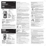
1. Meter Functions
Needle
Analog
Scale
Zero
Adjust
Screw
Zero
Ohms
Adjust
ment
Input Jacks
Function/
Range
Selector
Switch
Contents
1. Meter Functions
2. Specifications
2.1 For Your Safety
3. Operating Suggestions
3.1 Preliminary Adjustments
3.2 Internal Battery Condition
4. DC Voltage Measurement
4.1 Automotive Batteries
4.2 Alternators and Generators
4.3 Household Batteries
5. DC Milliamp Measurement
6. AC Voltage Measurement
6.1 Wall Receptacles
6.2 Appliance Receptacles
6.3 Circuit Breaker Panels
7. Resistance/Continuity Measurement
7.1 Extension Cords
7.2 Appliance Cords
7.3 Fuses
7.4 Switches
7.5 Heating Elements
7.6 Thermostats
8. Decibel Measurement
9. Battery and Fuse Replacement
1
Figure 1
Battery/
Fuse
Cover
Mirror

2.1 For Your Safety
1) Use extreme caution when checking electrical circuits.
2)
Do not stand in wet or damp work areas when
working with electricity. Wear rubber-soled boots or shoes.
3) Do not apply more voltage or current than
the set range of the multimeter will allow.
4) Do not touch the metal probes of the test
leads when making a measurement.
5) Replace worn test leads. Do not use test leads with broken
or tattered insulation.
6) Discharge a capacitor before measuring it.
7) Remove the test leads from the circuit being measured as
soon as the test is completed.
8) Do not measure voltage when the
function/range switch is set on the resistance (ohms) or the
current (mA) settings. Never measure current when the meter
is set on the resistance range. Never measure AC voltage
when the meter is set on DC voltage or DCmA. Setting the
meter on the incorrect function may burn out some of the
internal circuitry and may pose a safety hazard.
3. Operating Suggestions
1) Set the function/range switch to the proper position before
making a measurement. When the voltage or current is not
known, it MUST be determined that the capacity of the
selected range will handle the amount of voltage or current
in the circuit (see #3 under For Your Safety). Always start
with the highest range in the function. If the reading falls
within the range of a lower setting, reset the function/range
switch to the appropriate setting for greater accuracy.
2) Avoid placing the meter in areas where vibration, dust or dirt
are present. Do not store the meter in excessively hot,
humid or damp places. This meter is a sensitive measuring
device and should be treated with the same regard as other
electrical and electronic devices.
3) Using the meter in areas with high magnetic fields can result
in inaccurate readings. For greatest accuracy, lay the meter
flat on a non-metallic surface.
4
!
WARNING
!
WARNING
!
WARNING
!
WARNING
2. Specifications
Ranges: 12 measuring ranges
DC Voltage: 10-50-250-500 Volts
AC Voltage: 10-50-250-500 Volts
DC Current (Milliamperes): 0.5-50-250mA
Resistance (Ohms): Rx1K (resistance indicated multiplied by 1000)
1 Megohm max
Decibels: -20dB to +56dB on AC voltage ranges
Accuracy: DC voltage, mA = 4% full scale of range
AC voltage = 5% full scale of range
Resistance = 4° arc of scale length
Sensitivity: 2000 ohms per volt DC and AC
Function/Range Switch: 5 functions
13 positions
12 measuring ranges
Zero Ohms Adjustment Dial: Located on the left side of the housing; adjustment
dial is used to zero the needle indicator on the
ohms scale while shorting the test leads together.
Mechanical Zero
Adjustment Screw: Located directly below the center of the meter
scale; adjust needle indicator to read zero
at the left side of the scale before taking
any measurement.
Mirrored Scale Plate: The mirror on the scale plate is used to line up the
needle with its reflection to improve the reading
accuracy by preventing parallax error.
Recessed Input Jacks: Negative (-) input jack for black test lead, positive
(+) input jack for red test lead.
Important:
Read this operators manual thoroughly before using this
multimeter. This manual is intended to provide basic
information regarding this multimeter and to describe
common test procedures which can be made with this unit.
Many types of appliance, machinery and other electrical
circuit measurements are not addressed in this manual
and should be handled by experienced service technicians.
Use extreme caution when using this
multimeter. Improper use of this meter can result in
severe damage to property, severe personal injury or
death. Follow all instructions and suggestions in this
operators manual as well as normal electrical safety
precautions. Do not use this multimeter if you are
unfamiliar with electrical circuits and proper
test procedures.
3
!
WARNING

6
Resistance (Ohms - Ω)
Use the top scale for reading the resistance. If the meter
is set to X1k, multiply the resistance value by 1000Ω.
DC Voltage (V DC)
Use the middle scale directly below the mirror. Match the
dial setting to the highest number on the scale. If the setting
does not match one of the numbers, use a scale that can be
easily multiplied to give the setting (i.e. - for 500V, use the
50V scale and multiply the reading by 10).
AC Voltage (V AC)
Use the same numbers and procedures as used for
the DC voltage setting, but use the scale directly below
the numbers.
DC Milliamps
Use the same scale and procedure as used for the DC
voltage setting.
Decibel Gain (dB) - see pg. 15
Use the scale marked dB to read decibels. Use the chart
at the right of the scale for proper conversion.
3.2 Internal Battery Condition
Before making resistance or continuity tests, check the
condition of the internal battery. First turn the function/range
switch to the ohms Rx1K position. Short the test leads
together and the needle indicator should deflect to the
right side of the scale. Keep the test leads shorted together
while simultaneously turning the zero ohms adjustment
dial until the needle indicator reads zero at the right side
of the ohms (green) scale. If the needle will not zero,
replace the battery with a new 1.5 volt AA size battery
(see Battery Replacement).
4. DC Voltage Measurement
1) Fully seat the test leads in the correct input jacks, (-) black
lead, (+) red lead.
5
4) When the meter is not in use, keep the function/range
switch in the OFF position. This keeps the needle indicator
from deflecting or ”bouncing” excessively.
5) When disconnecting the test leads from the unit, always
grasp the leads where the input jacks meet the meter
housing. Never pull the leads out of the jacks by the
insulated wire or transport the meter using the test leads
as a carrying strap.
6) Never immerse the meter in water or solvents. To clean
the housing use a damp cloth with a minimal amount of
mild soap.
7) If the resistance (ohms) function of the meter is not going to
be used for a week or more, remove the internal battery to
avoid potential leaks that may damage the unit.
3.1 Preliminary Adjustments
Fully seat the test leads in the correct input jacks. If
necessary, using a small flat tip screwdriver, slowly turn
the mechanical zero adjustment screw clockwise or
counterclockwise until the needle indicator is directly over
the three black zeros at the left end of the scale.
Analog Meter:
Reading the Scale
General
The first step in reading the analog scale is to align the
needle with the scale. This is achieved by locating the
mirror on the scale. Line the needle up with its reflection.
When the reflection is hidden by the needle, the needle
is properly aligned.
DC
10
20
50
100
200
500
2K
5K
10K
6
8
1K
Resistance
(Ohms)
Scale
DC Voltage
& Milliamps
Scale
Common Markings
for both the AC &
DC Voltage Scales
AC Voltage Scale
dB Scale for Transistor
Gain Measurement
}

8
corrosion resistance, coat the terminals and connectors with
GB #OX-100 anti-oxidant compound (available at your local
hardware store). Replace and tighten the terminal connectors.
Secondly, if the terminals and connectors are making good
contact, touch the test leads to the battery and vehicle
framework as described above (see fig. 2). Note the reading
of the meter. Get an assistant to turn on the headlights while
the test leads are making contact. The needle indicator should
drop a few volts. Should the needle indicator drop 5 volts or
more, the battery should be charged or possibly replaced if
the voltage drop is significant. The circuit may need to be
checked further for problems within the electrical system that
may be draining the battery.
4.2 Alternators and Generators
Set the function/range switch to the 50V DC range. While the
engine is idling at normal operating speed, touch the black (-)
test lead to the metal framework of the vehicle, then touch
the red (+) test lead to the output terminal connector. The
alternator output cable is always the heaviest gauge cable
attached to the alternator (see fig. 3). The needle indicator
should read 12 volts or more. If the needle indicator moves
sporadically, the cable may need to be tightened. If the
engine is idling lower than is specified in the vehicle owners
manual, the voltage reading will be lower. If the output
voltage is significantly low, the alternator may require
service or replacement.
When making automotive measurements,
observe safety precautions. Stay away from the fan blades,
belts and other moving parts of the engine. Keep the
multimeter and its leads away from moving parts.
2) Set the function/range switch to the appropriate DC voltage
range. If the voltage is unknown, use the highest range. If
the voltage applied falls within the range of a lower setting,
reset the function/range switch to the appropriate setting for
greater accuracy.
3) If the polarity of the circuit to be tested is known, touch
the black test lead to the neutral side. If the polarity is
unknown, touch the test leads to opposite sides of the
circuit. If the needle indicator deflects to the left of the scale,
reverse the test leads.
Use the chart below as a guide to reading DC
voltage measurements:
DC V Read and
range following multiply
setting scale reading by:
10 0-10 1
50 0-50 1
250 0-250 1
500 0-50 10
Common DC Voltage Measurements
4.1 Automotive Batteries
Set the function/range switch to 50V DC. First check the
quality of the battery terminal connector by touching the
red (+) test lead to the connector while touching the black (-)
test lead to any bare metal framework of the vehicle. The
meter should read 12 volts or higher on the 0-50 scale with
all of the vehicle accessories turned off. If the needle indicator
moves sporadically, this indicates a bad terminal connection.
Remove the terminal connectors and clean both terminals
and connectors thoroughly. For improved conductivity and
7
Figure 2
Figure 3
!
WARNING

Do not apply voltage to the test leads
while the meter is set in the milliamp range. See #8
For Your Safety.
6. AC Voltage Measurement
1) Fully seat the test leads in the correct input jacks.
2) Set the function/range switch to the appropriate AC voltage
range. If the voltage is unknown, use the highest range. If
the voltage applied falls within the range of a lower setting,
reset the function/range switch to the appropriate setting for
greater accuracy.
3) Touch the test leads to the circuit under test. With AC
voltage, the polarity of the test leads is not a factor.
Use the chart below as a guide to reading AC
voltage measurements:
AC V Read and
range following multiply
setting scale reading by:
10 0-10 1
50 0-50 1
250 0-250 1
500 0-50 10
Common AC Voltage Measurements
6.1 Wall Receptacles
If the receptacle is controlled by a switch, make sure the
switch is ON. Set the function/range switch to 250V AC.
Touch the test leads to the “hot” and “neutral” slots of the
receptacle (see fig. 5A). The needle indicator should read
120V AC on the 0-250 scale. To test for proper grounding of
the receptacle, touch one test lead to the “hot” (narrow) side of
the receptacle, and the other test lead to the ground slot. The
meter should read 120V AC as before. To test for proper
grounding of non-polarized receptacles (fig.6), alternately
touch the test leads between the receptacle slots and the wall
plate screw. The meter should indicate 120V AC when one
test lead contacts the “hot” side of the receptacle. If ground
10
4.3 Household Batteries
Set the function/range switch to 10V DC to test household 1.5
volt through 9 volt batteries. Touch the red (+) test lead to the
(+) terminal and the black (-) test lead to the (-) terminal of the
battery. Read the 0-10 scale to determine the condition of
the battery.
5. DC Milliamp Measurement
1) Fully seat the test leads in the correct input jacks.
2) Set the function/range switch to the 250 DCmA setting.
3) Put the test leads in series with the circuit (in line with the
circuit) so that the circuit current passes through the
multimeter in order to make the measurement. If the needle
indicator deflects to the left, reverse the test leads. Read
the measurement on the 0-250 scale.
Common DC Milliamperage Measurements
It is important to point out that milliamps can also be
expressed as thousandths of an Ampere; therefore 250
milliamps is 250 thousandths of one Amp. The 250mA
function of your multimeter is commonly used by electronics
repair technicians and hobbyists to troubleshoot various low
voltage circuits. Although not normally used for electrical
troubleshooting around the home, this function can be used to
measure the milliamperage draw of household items such as
flashlights, and other battery operated devices that do not
draw more than 250 mA. In fig. 4 the red (+) test lead is
hooked up to the (+) terminal of the lantern battery while the
black (-) test lead is hooked up to the bulb. The meter will
indicate the milliamperage draw when the flashlight switch is
thrown in the ON position.
Figure 4
!
WARNING
9

7. Resistance/Continuity Measurement
For resistance and continuity testing POWER MUST BE OFF:
1) Fully seat the test leads in the input jacks.
2) Set the function/range switch to the Rx1K position
(resistance indicated multiplied by 1000) and short the test
leads together. Using the zero ohms adjustment dial, slowly
turn the dial until the needle indicator reads -0- ohms at the
right end of the ohms scale. If the needle will not zero,
replace the internal battery with a new 1.5 volt AA size
battery (see Battery Replacement).
3) Touch the test leads to the resistance or non-energized
circuit to be measured. Measure the value of the reading on
the green ohms scale and multiply the reading by 1000. If
you’re making basic continuity tests, the needle indicator
should move all the way to the right side of the ohms scale
if continuity exists.
Note: When switching the unit back and forth from ohms
to other functions, always zero the needle indicator before
taking another reading. Failure to zero the needle before
taking resistance/continuity measurements will result in
inaccurate readings.
Common Resistance and Continuity Measurements
Continuity tests are probably the most frequently performed
electrical troubleshooting procedures around the home.
ALWAYS REMEMBER THAT CONTINUITY CHECKS ARE
TO BE MADE WITH THE POWER TO THE CIRCUIT
TURNED OFF. Polarity of the test leads is not a factor in
making continuity checks.
12
contact cannot be made on the wall plate screw, remove the
wall plate and touch the electrical box with the test lead in
the same manner as before. The meter should read 120V
AC with one test lead touching the electrical box and the
other touching the live side of the receptacle. If not, the
receptacle is not properly grounded.
6.2 Appliance Receptacles
Set the function/range switch to 250V AC. Touch the test leads
to the receptacle slots. The meter should read 240V AC between
the two “hot” sides of the receptacle, and 120V AC between the
neutral slot and either of the two “hot” sides (see fig. 7).
6.3 Circuit Breaker Panel
To test for defective circuit breakers, set the function/range
switch to the 250V AC. Touch one test lead to the neutral
(buss) terminal strip of the breaker panel and the other test
lead to the terminal on the circuit breaker (see fig. 8). The
meter should read 120V AC on the 0-250 scale.
11
Figure 8
Figure 7
Figure 5
Figure 6
5A
5B

7.3 Fuses
Note: With the power OFF, always remove a fuse from its
socket before testing it. With cartridge fuses, touch the test
leads to each end of the fuse (see fig. 10). If the fuse is good,
the needle indicator will move to -0- ohms. If not, replace the
fuse. On plug-type fuses, touch the the test leads on the
bottom contact and the other on the threaded metal contact
(see fig. 11). On time-delay/tamper-proof fuses, the other
metal contact is at the top of the ceramic threads.
7.4 Switches
Cut off the power source to the switch. If necessary, remove
the switch. Turn the switch to the ON position and touch the
test leads to the switch terminals (see fig. 12). If the switch is
good, the needle indicator will move to -0- ohms. If not,
replace the switch. On other switches such as three-way
light switches or double pole double throw (ON-OFF-ON)
switches, each ON position will need to be tested. Alternate
the test leads between the switch terminals to determine
which two terminals control that ON position.
14
7.1 Extension Cords
Unplug the cord. Set the function/range switch to the Rx1K
position. Touch one of the test leads to one of the metal prong
ends of the cord, and insert the other test lead in either one of
the receptacle slots on the other end of the cord, making sure
the test lead is making good contact with the receptacle (see
fig. 9). If the needle indicator does not move to -0- ohms,
insert the test lead into the other receptacle slot, again making
sure of good contact. If the needle indicator still does not
move the cord has a break and should be replaced.
7.2 Appliance Cords
Unplug the appliance from its power source. Turn its power
switch to the ON position. Touch the test leads to the metal
prong ends of the cord. The meter should indicate a low
resistance value. If not, flex the cord while the leads are still
in contact with the metal prongs. If the needle indicator
moves sporadically while the cord flexes, there may be a
broken conductor in the cord. If the needle indicator does not
move at all, there may be an open circuit in the appliance.
Should it be determined that the cord is not the source of the
problem the appliance may need to be disassembled in
order to pinpoint the problem. Refer to the owners manual of
the appliance. The manufacturer of the appliance may
require that the appliance be serviced only by a qualified
repair technician.
13
Figure 11Figure 10
Figure 12
Figure 9

16
9. Battery and Fuse Replacement
1) Remove the screw in the back cover of the meter and
carefully separate the back cover from the front.
2) Note the polarity of the battery when removing it from its
compartment and replace.
3) Use GB catalog number GF-0306 0.5A/250V
replacement fuses.
4) Carefully replace the back cover and tighten the screw.
Do not overtighten, as this may strip the threads in the
meter housing.
7.5 Heating Elements
Household appliances such as coffee makers and water
heaters contain heating elements which may require
troubleshooting. When making continuity checks on heating
elements, disconnect the element(s) from the circuit(s) that
supply it/them. Touch the test leads, one on each end of
the element and observe the needle indicator. The reading
should indicate low ohms. If the needle indicator doesn’t
move, the heating element is broken. If the element(s)
show that continuity exists, test for continuity of the
circuit(s) that feed the element(s).
7.6 Thermostats
Make sure the thermostat control is in the OFF position.
Remove the thermostat cover. Touch the test leads to the
contact points on the thermostat. The needle indicator
should move to read -0- ohms. If not, either one of them
may be loose or broken.
8. Decibel Measurement
The decibel feature of this multimeter is for transistor gain
measurement in electronic circuits and should not be
confused with audio decibels. This function is used
primarily by electronics technicians to measure the power
gain in transistors, and is rarely encountered in home
project applications.
1) Fully seat the test leads in the correct input jacks.
2) Set the function/range switch to any one of the AC voltage
ranges and read the decibel measurement on the bottom
(red) scale of the faceplate. Based on the AC voltage
range you selected, you will need to compute the actual
measurement by using the decibel conversion chart
located at the bottom right of the faceplate.
Important: For absolute decibel measurements, circuit
impedance must be at least 600 ohms. -0- decibels = 1
milliwatt in a 600 ohm impedance (equivalent to 0.775 volts
across 600 ohms).
15
Order Form
Learn more about using multimeters with "How To Use
Your Multitester For Electrical Testing and Troubleshooting".
A 160 page guide to using analog and digital multimeters.
Only available in English. Contains nine chapters of easy to
understand instructions on basic household, automotive
electrical and electronic circuit testing. Packed with
illustrations. Paperback bound. Available wherever
multimeters are sold or:
For customers within the US, send check or money order for
$15.23 per copy ($13.23 plus $2.00 per copy shipping and
handling) to:
Gardner Bender
6101 N. Baker Rd.
Milwaukee, WI 53209
PLEASE PRINT CLEARLY
Name_________________________________________ _________
Address______________________________________ __________
City______________________State__________ Zip_____________
Qty. Ordered___ __________________

Gardner
Bender
www.gardnerbender.com
PO Box 3241 • Milwaukee, WI 53201-3241 • 414-352-4160
6615 Ordan Drive • Mississauga, Ontario L5T 1X2 • 905-564-5749
ZX000132 Rev. A
/