Page is loading ...

Dial Settings
3.1 AC Volts
There are two ranges for measuring AC voltage, 200 V and 500 V. For more accurate measurements under 200 volts use the
200 Volt setting.
1. Set the function/range switch to the appropriate AC V range shown above.
2. Touch the test leads to the circuit under test. With AC voltage, the polarity of the test leads is not a factor.
NOTE: It is best to touch one of the test leads to ground or Neutral first and then touch the 2nd test lead to the hot wire.
3. Read the value of the measurement displayed.
4. Typical AC Voltage measurements include wall outlets, appliance outlets, motors, light fixtures and switches. When measuring outlets the
specially spaced lead holders allow for single one hand testing.
3.2 DC Volts
There are four ranges for measuring DC voltage, 2, 20, 200 V and 600 V. For more accurate measurements use the lowest range possible
without exceeding the value.
1. Set the function/range switch to the appropriate DC V range shown above.
2. Touch the test leads to the circuit under test. With DC voltage, the polarity of the test leads is a factor. Touch the black (common) test lead
to the negative DC source first and red (positive) test lead to the “live” source second.
3. Read the value of the measurement displayed. If the leads are reversed a “-“ indicator will appear on the display.
4. Typical DC Voltage measurements include car batteries, automotive switches and household batteries.
3.3 Resistance
There are five ranges for measuring resistance 200, 2K, 20K, 200K and 2 Meg Ohms. For more accurate measurements use the lowest
range possible without exceeding the value.
when measuring resistance always make sure the power is off.
1. Set the function/range switch to the appropriate resistance (ohms) range shown above.
2. Touch the test leads to the resistor or non-energized component to be measured. Use the 2000K range when testing for resistance values
in electronic components such as resistors and potentiometer. If the value of the component falls within the range of another setting, reset
the function/range switch to that setting for a more accurate reading.
3. Read the value of the measurement displayed. With resistance measurements, the polarity of the test leads is not a factor.
4. Typical resistance/continuity measurements include resistors, potentiometer, switches, extension cords and fuses.
3.4 Household Battery Testing
There are two ranges for measuring common household batteries, 1.5 V and 9 V.
1. Set the function/range switch to the appropriate battery position.
2. Touch the test leads to the positive and negative terminals on the battery. With DC voltage, the polarity of the test leads is a factor. Touch
the black (common) test lead to the negative (-) terminal and the red test lead to the positive (+) terminal.
3. Read the value of the measurement displayed. If the leads are reversed a “-“ indicator will appear on the display.
Battery Replacement
1. Remove protective boot from test unit.
2. Remove the screws in the back cover of the tester and carefully separate the back cover form
the front.
3. Remove the battery from the contacts, noting the polarity of the battery terminals
and contacts.
4. Replace with one fresh 9 volt battery.
Note: Do not use rechargeable batteries in this unit.
5. Carefully, replace the back cover and tighten the screws. Do not overtighten the screws as this
may strip the threads in the tester housing.
6. Replace protective boot.
!
WARNINGWARNING
V11A
1.0 METER FUNCTIONS
2.0 READ FIRST: IMPORTANT SAFETY INFORMATION
Read this operators manual thoroughly before using this mulitimeter. This manual is intended to provide basic information
regarding this meter and to describe common test procedures which can be made with this unit. Many types of appliance,
machinery and other electrical circuit measurements are not addressed in this manual and should be handled by
experienced service technicians.
Use extreme caution when using this multimeter. Improper use of this meter can result in severe damage to
personal injury or death. Follow all instructions and suggestions in this operators manual as well as observing
normal electrical safety precautions. Do not use this meter if you are unfamiliar with electrical circuits and proper
test procedures.
2.1 For Your Safety
1) Use extreme caution when checking electrical circuits.
2) Do not stand in wet or damp work areas when working with electricity. Wear rubber soled boots or shoes.
3) Do not apply more voltage or current than the set range of the multimeter will allow
4) Do not touch the metal probes of the test leads when making a measurement.
5) Replace worn test leads. Do not use test leads with broken or tattered insulation.
6) Discharge a capacitor before measuring it.
7) Remove the test leads from the circuit being measured as soon as the test is completed. Never reset the function/range switch to
another range while the leads are still in contact with a circuit.
8) Do not measure voltage when the function/range switch is set on the resistance (ohms) settings. Do not measure current when the
meter is set on the resistance range. Never measure AC voltage when the meter is set on DC voltage. Setting the meter on the
incorrect function may burn out some of the internal circuitry and may pose a safety hazard.
9) Damaged meters are not repairable nor is calibration possible. Damaged meters should be disposed of.
3. Operating Instructions
1. Set the function/range switch to the proper position before making a measurement. When the voltage is not known, it MUST
bedetermined that the capacity of the selected range will handle the amount of voltage in the circuit (see #3 under “For Your Safety”).
2. Avoid placing the meter in areas where vibration, dust or dirt are present Do not store the meter in excessively hot, humid or damp places.
This meter is a sensitive measuring device and should be treated with the same regard as other electrical and electronic devices.
3. When the meter is not in use keep the meter turned to keep the battery from discharging.
4. When disconnecting the test leads from the unit, always grasp the leads where the input jacks meet the tester housing. Do not pull the
leads out of the jacks by the insulated wire or transport the tester using the test leads as a carrying strap.
5. Do not immerse the meter in water or solvents. To clean the housing use a damp cloth with a minimal amount of mild soap.
NOTE: With any measurement made by this meter, there will be some fluctuation of the digital display. This is due to the meter’s sampling
method. This unit samples at a rate of 2 times per second, thus the fluctuation of the readout.
!
WARNINGWARNING
!
WARNINGWARNING
!
WARNINGWARNING
!
WARNINGWARNING
!
WARNINGWARNING
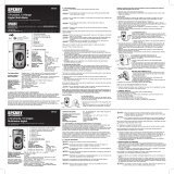
1. 3/12 digit LCD display
Pantalla de cristal líquido de 3/12
dígitos
Affichage numérique 3 1/2 po
2. 14 position Function/Range dial
Dial de 14 posiciones de
función/rango
Sélecteur de fonction/plage 14
positions
3. AC Volts
Voltios de CA
Volts c.a.
4. DC Volts
Voltios de CC
Volts c.c.
5. Resistance
Resistencia
Résistance
6. Battery Test
Prueba de batería
Test de pile
7. On/Off button
Botón de encendido y
apagado
Bouton Marche/Arrêt
8. Low Battery Indicator
Indicador de batería baja
Indicateur de pile faible
9. Common input jack
Toma de entrada común
Prise d'entrée commune
10. Positive input jack
Toma de entrada positiva
Prise d'entrée positive
11. Wrap around lead storage
Almacenamiento envolvente
de conductores
Rangement des fils par
enroulage
12. Snap in probe storage
Almacenamiento insertable de
la sonda
Rangement des sondes par
pression
13. Protective rubber boot
Manguito de caucho protector
Gaine protectrice de
caoutchouc
7
Meter type: Manual
Functions: 4
Ranges: 14
Display Count: 2000
Input impedance: 10 Meg Ohm
AC Volt ranges: 200 / 500 (2.5% + 5 digits)
DC Volt Ranges: .2 / 2 / 20 / 200 / 600 (1.2%+2 digits)
Resistance Ranges: 200 / 2k / 20k / 200k / 2M (1.5% + 2 digit)
Battery Test Ranges: 1.5 Volt and 9 Volt
Auto Off 30 Minutes
Battery type: 9 Volt
Battery Life: 100 hours with carbon-zinc cells, 200 hours with alkaline cells
under normal conditions.
Over Range Indication: The three least significant digits are blank and the number “1”
is displayed at the left when the range capacity is exceeded
by the input.
Polarity Indication: “-“ is displayed for negative polarity
Agency Approvals: ETL, CE, CAT III 600V
Contents
1. Meter Functions
2. Specifications
2.1 For Your Safety
3. Operating Instructions
3.0 For Your Safety
4. AC Voltage Measurement
3.1 AC Volts
5. DC Volts Measurement
3.2 DE Volts
6. Resistance/Continuity Measurement
3.3 Resistance
8. Battery
4 Function, 14 Range
Digital Multi-Meter
Owners Manual
• Read this owners manual thoroughly
before use and save
Milwaukee, WI 53209
1.800.822.9220
www.gardnerbender.com
ZX402 Rev. A
GDT-3190
V11A
Multímetro digital de 4
funciones, 14 rangos
Manual del propietario
• Lea completamente este manual del
propietario antes del uso y consérvelo
para referencia futura.
GDT-3190
Contenido
1. Funciones del probador
2. Especificaciones
2.1 Para su seguridad
3.0 Instrucciones operativas
3.1 Voltios de CA
3.2 Voltios de CC
3.3 Resistencia
3.4 Prueba de batería casera
Especificaciones del medidor
tipo de medidor: manual
funciones: 4
rangos: 14
Cuenta en pantalla: 2000
impedancia de entrada: 10 Meg Ohmios
Rangos de voltios de CA: 200 / 500 (2.5% + 5 dígitos)
Rangos de voltios de CC: .2 / 2 / 20 / 200 / 600 (1.2%+2 dígitos)
Rangos de resistencia: 200 / 2k / 20k / 200k / 2M (1.5% + 2 dígitos)
Rangos de prueba de batería: 1.5 Voltios y 9 Voltios
Apagado automático 30 minutos
tipo de batería: 9 voltios
Duración de la batería: 100 horas con pilas de carbono-cinc, 200 horas con pilas
alcalinas bajo condiciones normales.
Indicación sobre rango: Los tres dígitos menos significativos están en blanco y
aparece el número “1” a la izquierda cuando la entrada
supera la capacidad de rango.
Indicación de polaridad: Aparece “-“ para la polaridad negativa
Aprobaciones de agencias: ETL, CE, CAT III 600V
2.0 IMPORTANTE:2.0 IMPORTANTE:
Lea este manual del operador completamente antes de utilizar este multímetro. El fin de este manual es proporcionar
información básica relacionada con este multímetro y describir procedimientos básicos de prueba que pueden realizarse
con este probador. La medición de muchos tipos de aparatos, maquinaria y otros circuitos eléctricos no se menciona en
este manual y debe solicitarse la asesoría de técnicos de servicio experimentados.
PRECAUCION SEA SUMAMENTE PRECAVIDO CUANDO USE ESTE MULTÍMETRO. EL USO INDEBIDODE ESTE
PROBADOR PUEDE PROVOCAR GRAVES DAÑOS MATERIALES Y LESIONES PERSONALES GRAVES O FATALES. SIGA TODAS LAS
INSTRUCCIONES Y SUGERENCIAS DE ESTE MANUAL DEL OPERADOR Y OBSERVE ADEMAS LAS PRECAUCIONES NORMALES
DE SEGURIDAD ELECTRICA. NO UTILICE ESTE MULTIMETRO SI NO TIENE EXPERIENCIA EN CIRCUITOS ELECTRICOS Y
DESCONOCE LOS PROCEDIMIENTOS CORRECTOS DE PRUEBA.
2.1 Para su seguridad
1) Sea sumamente precavido cuando revise circuitos eléctricos.
2) Aléjese de las áreas mojadas o húmedas cuando trabaje con electricidad. Use botas o zapatos con suelas de goma.
3) No aplique más voltaje o corriente de lo permitido por la escala seleccionada en el multímetro.
4) No toque las puntas metálicas de los conductores de prueba cuando realice mediciones.
5) Reemplace los conductores de prueba desgastados. No use conductores de prueba con aislamiento roto o agrietado.
6) Descargue un condensador antes de medirlo.
7) Retire los conductores de prueba del circuito bajo prueba tan pronto concluya la prueba. Nunca cambie de una escala a otra por medio
del selector de función/escala mientras los conductores estén todavía en contacto con un circuito.
8) No mida el voltaje cuando el selector de función/escala esté colocado en la posición de resistencia (ohmios) o de corriente (10
amperios). Nunca mida la corriente cuando el selector esté colocado en la escala de resistencia. Nunca mida el voltaje de corriente
alterna (AC) cuando el selector esté colocado en la escala de voltaje de corriente continua (DC) o de 10 amperios DC. Si el probador
se usa en la función incorrecta, se pueden fundir algunos de los circuitos internos, resultando en un riesgo de seguridad.
9)
Los medidores dañados no son reparables ni es posible calibrarlos. Los medidores dañados deben descartarse.
3.0 Instrucciones operativas
1.
Ponga el interruptor de función/rango en la posición adecuada antes de comenzar a medir. Cuando no se conozca el voltaje, DEBE
determinarse que la capacidad del rango seleccionado aceptará la cantidad de voltaje del circuito (vea el número 3 de la sección “Para
su seguridad”).
2. Evite poner el medidor en áreas donde haya vibración, polvo o suciedad. No guarde el medidor en lugares excesivamente calientes o
húmedos. Este medidor es un dispositivo medidor sensible y debe tratarse con la misma consideración que otros eléctricos y
electrónicos.
3. Cuando no esté en uso el medidor manténgalo apagado para que no se descargue la batería.
4. Al desconectar los conductores de prueba de la unidad, siempre tome los conductores donde se encuentran las tomas de entrada con
el alojamiento del probador. No saque los conductores de las tomas tirando del cable aislado ni transporte el probador usando los
!
ADVERTENCIA
ADVERTENCIA
!
ADVERTENCIA
ADVERTENCIA
!
ADVERTENCIA
ADVERTENCIA
!
ADVERTENCIA
ADVERTENCIA
!
ADVERTENCIA
ADVERTENCIA
conductores de prueba como correa para llevar.
5. No sumerja el medidor en agua ni solventes. Para limpiar el alojamiento use un paño húmedo con una mínima cantidad
de jabón suave.
NOTA: Con cualquier medida efectuada por este medidor, habrá algo de fluctuación de la pantalla digital. Esto se debe al método
de muestreo del medidor. Esta unidad muestrea a razón_de 2 veces por segundo, por eso se produce la fluctuación de la lectura.
Selecciones del dial
3.1 Voltios de CA
Hay dos rangos para medir el voltaje de corriente alterna, 200 V y 500 V. Para obtener mediciones más exactas bajo 200 voltios use la
selección de 200 voltios.
1. Ponga el interruptor de función/rango en el rango de CA V adecuado que se indica más arriba.
2. Toque el circuito a prueba con los conductores de prueba. Con voltaje de CA, la polaridad de los conductores de prueba no es
un factor.
NOTA: Es mejor tocar tierra o neutro primero con uno de los conductores de prueba y luego tocar el cable energizado con el 2do
conductor de prueba.
3. Lea el valor de la medida mostrada.
4. Las medidas típicas de voltaje de CA incluyen tomacorrientes, receptáculos de pared, enchufes para electrodomésticos, motores,
luces e interruptores. Al medir tomacorrientes los portaconductores separados especialmente permiten probar usando una sola mano.
!
ADVERTENCIA
ADVERTENCIA
DC Volts
AC Volts
Battery test
Resistance
1
2
5
6
10
9
3
8
7
4
Volitos de CC
Voltios de CA
Pruba de batería
Resistencia
GDT-3190 rA 2-09 manual.qxd 2/23/09 3:02 PM Page 1
/