Page is loading ...

INSTRUCTION MANUAL
Part Numbers: A1250 and A1350
ACADIA®

2
Section Page
Introduction .......................................................................... 3
Safety Notice......................................................................... 4
Specifications ........................................................................ 5
Unpacking and Inspection............................................................... 6
Installation Information ................................................................. 7
Filter Replacement and Disposal ......................................................... 12
Spare Replacement Parts............................................................... 13
Acadia Model with Alert Monitor ......................................................... 14
Maintenance ......................................................................... 18
Troubleshooting....................................................................... 18
Warranty ............................................................................ 18
On-Line Warranty Registration ........................................................... 18
If You Need Assistance ................................................................. 18
TABLE OF CONTENTS
LIST OF ILLUSTRATIONS
Figure Title Page
1 Acadia Amalgam Separator Assembly, PN A1250 .................................3
2 Acadia Amalgam Separator Assembly Outline/Dimension Drawing ....................5
3 Acadia Amalgam Separator Assembly Component Identification .....................6
4 Typical Acadia Amalgam Separator Installation Configurations . . . . . . . . . . . . . . . . . . . . . . .7
5 Changing the Acadia Amalgam Separator Input to Right-side Orientation...............7
6 Separator Wall Mounting .....................................................8
7 Separator Inlet and Outlet Connection Fittings Install Locations.......................8
8 Solid Collection Filter Installation ..............................................8
9 Typical Acadia Amalgam Separator Installation Configurations . . . . . . . . . . . . . . . . . . . . . . .9
10 Acadia Amalgam Separator Connection to the Treatment Operatory Output Piping . . . . . . .9
11 Acadia Amalgam Separator Connection to a STS Pump/CAS Tank Vacuum System
(Direct connection to Separation Tank.) ........................................10
12 Acadia Amalgam Separator Connection to a VacStar System
(Direct pump connection. No Separation Tank.)..................................11
13. Acadia Amalgam Separator Assembly, PN A1350, Alert Monitor Module
Front Panel View ..........................................................14
14. Acadia Alert Monitor Module Accessory Kit, P/N A1378 ...........................14
15. Acadia Alert Monitor Panel Electronics Enclosure ...............................15
16. Typical Wire Routing Through Strain Reliefs .....................................16
17. Acadia Alert Monitor Module Electrical Connection Configurations ..................16
18. Acadia Alert Monitor Panel Assembly Installation and
Liquid Level Sensor Cable Connection .........................................17
19. Acadia Amalgam Separator with Acadia Alert Monitor Module, PN A1350 ............17

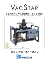
Figure 1. Acadia Amalgam Separator Assembly
LARGE PARTICLE
INLET FILTER
STRAINER
INPUT CONNECTOR
FROM OPERATORIES
DISPOSABLE SOLID
COLLECTION FILTER
OUTPUT CONNECTOR
TO VACUUM SYSTEM
Direct to Liquid Pump
or
Direct to Separation Tank
of a Dry Pump System
This manual covers the installation and maintenance of the Acadia Amalgam Separator Assemblies PN A1250 and
A1350. Although both units provide the same high level solid collection function, the Acadia PN A1350, also incorpo-
rates an Acadia Alert Monitor Module. This addition feature monitors the Solid Collection Filter and provides a visual
and audible indication when the lter needs replacement.
Installation tacks include the following:
Adding to any existing liquid ring or dry vacuum system.
Installing as part of a new liquid ring or dry vacuum system.
The manual provides additional maintenance and troubleshooting information for each unit, as well as, instructions
to replace a filled Disposable Solid Collection Filter. The Acadia Amalgam Separator is hereafter referred to as the
Separator in this manual. Make sure to review and follow the information specific to your installation to ensure that
the Separator provides the highest level of safe service.
Important: Each kit provides the necessary parts to connect to both a STS Pump with CAS Tank and VacStar vacuum systems
manufactured By Air Techniques. If the existing installations need different size fittings or hose lengths, they must be
provided by the installer.
As shown by Figure 1, both Separator models are designed to exceed ISO 11143 requirements in the removal of
amalgam from a dental suction system's wastewater stream. Installed between dental operatories and vacuum
pumps, the Separator uses a disposable lter comprised of a sedimentation labyrinth containing articulated foam
lters and a granular lter media. Each unit is designed to provide continuous cyclonic separation action of liquids
and solids from gases causing a sedimentation process where high-density particles (Amalgam) fall from suspen-
sion in the wastewater stream and become trapped within the lters. The unit has been independently tested and
certified to ISO 11143.
Features include:
Capable of processing euent for up to ten (10) operatories.
Exceeds the ISO 11143 standard for separation eciency.
Continuous cyclonic separation of liquids and solids from gases.
Reusable large particle inlet lter strainer.
Minimal maintenance required.
Disposable Collection Filter.
• Easily removed using a quarter turn and pull.
• Transparent housing enables user monitoring of capacity and when to replace lter.
• Closure Cap provided to seal Disposable Collection Filter for transport.
Mounting & Connections
• Multiple mounting congurations (Wall Mount / Floor Mount).
• Quick and easy installation using included tubing and plumbing ttings.
• Custom molded clips allow easy assembly and disassembly of connection components.
• Multiple inlet connection orientations that accommodates standard 1½ inch diameter pipe using a no-
hub coupling or provided 1½ ID inch hose.
INTRODUCTION
AMALGAM SEPARATOR
CHASSIS/MOUNTING
BRACKET P/N A1297
3
Note: Part Number A1250 is shown. Part
Number A1350, an Acadia model
with the Alert Monitor Module is
also available. See page 14.

4
SAFETY NOTICE
Knowledge of General Safety
The Separator has been designed to minimize exposure of personnel to hazards. While the equipment is designed
for safe operation, certain precautions must be observed. Use of the Separator not in conformance with the
instructions specified in this manual may result in permanent failure of the unit.
Users must exercise every precaution to ensure personnel safety, and be familiar with the general safety procedures
concerning the Separator and associated vacuum systems, which include the following.
Observe all local codes and relevant regulations when installing the Separator.
Converting or modifying the Separator in any way is strictly prohibited. In such cases, any and all warranties will
immediately become invalid.
The operator must be knowledgeable in the operation of the appliance.
The product is not designed to be used in medical treatment areas where there exists the danger of explosion.
Areas where explosions could occur are those where ammable anesthetic material, skin cleansers, oxygen and
skin disinfectants are present. This appliance is not to be used in areas where the atmosphere could cause re.
Authorized Dealer Service Only.
The Separator is intended to be installed and serviced only by an authorized dealer service technician. Failure to heed
this warning may result in equipment damage or personal injury, and will void any and all warranties. Contact your
authorized dealer for service information.
Dental Waste Handling
Solid Collection Filters collect waste materials from dental procedures. All maintenance personnel must be familiar
with the procedures and practices for handling such dental waste and exercise every precaution to ensure personnel
safety. Additionally personnel must follow all local, state and/or federal laws and regulations for the proper disposal of
dental waste containing mercury. Any operation, procedure or practice, which, if not strictly observed, may result
in injury or long-term health hazards to personnel and should be handled, stored and disposed of according to
regulations applying to dental waste containing mercury.
Correct Usage
The Separator is for Dental Use only. Any use of the Separator that is not described in this Instruction Manual is
deemed to be incorrect usage.
Incorrect Usage
Any use of the Separator above and beyond that laid down in this Instruction Manual is deemed to be incorrect usage.
The manufacturer cannot be held liable for any damage resulting from incorrect usage. The operator will be held liable
and bears all risks.

5
Number of dental units serviced Up to 10
Maximum Liquid ow rate 1 liter per minute (0.26 gal per minute)
Liquid surge capacity 3 liters (0.79 gal)
Solids collection capacity 600 mL (0.16 gal)
Separation eciency Exceeds ISO 11143 requirements
Maximum Vacuum 50.80 cm/Hg (20 in/Hg)
Inlet Filter Screen Size 6 mm (0.24 in)
Classication Type 3 per ISO 11143
Connection type 3.81 cm (1½ in) Hose barb adaptor with retaining clip
Mounting Attached chassis/mounting bracket provided
Weight (empty) 9.5 kg (21 lbs)
Dimensions Width Depth Height
53 cm 38 cm 69 cm
(21 in) (15 in) (27 in)
SPECIFICATIONS
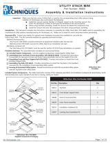
Figure 2. Acadia Amalgam Separator Assembly Outline/Dimension Drawing
37.4 cm
(15 in)
52.3 cm
(21 in)
68.3 cm
(27 in)

6
Installation Kits
Description Part No. Quantity
Installation Accessory Kit A1359 1
1½ inch ID Clear with White Spiral Hose
Note: If more than 6 feet of hose is needed, order additional P/N 54521 by the foot. 54521 6 Feet
1½ inch MNPT X 1-1/2 inch BARB Connector Adapter 57253S 1
1½ inch SLIP X 1-1/2 inch FNPT PVC Connector Adapter 54234 1
1.31 - 2.25 inch Diameter Hose Clamp 57169 4
1½ inch SPG X 3/4 inch FNPT Reducing Bushing A1164 1
1½ inch SPG X 1 inch FNPT, Reducing Bushing 55552 1
1½ inch Connector Flexible Coupling (No Hub) 57238 2
Foot Installation Kit A1399 1
Foot; Non Skid,.5 + .1/-0 HIGH X 1"Diameter, #8 screw 61173 4
Screw; 8-32 X 5/8, Phillips Pan Head, 18-8 S.S. 30463 4
#8, Flat Washer,18-8 SS 30052 4
8-32, Hex Nut, KEP, SS 31577 4
Wall Mounting Kit A1420 1
#10 X 1 inch, Anchor, Plastic 30936 4
#12 X 3/4 Type A, Phillips Pan Head, 30935 4
#10, Flat Washer,18-8 SS 30024 4
Important: Installation Accessory Kit, P/N A1359 provides the necessary parts to connect to both a STS Pump with CAS Tank and
VacStar vacuum systems manufactured by Air Techniques. If the existing installations need different size fittings or
hose lengths, they must be provided by the installer.
Installation Kit Components
The table below lists the supplied parts used to connect the Separator to new or existing vacuum systems.
UNPACKING AND INSPECTION
Unpacking
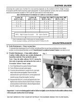
As shown by Figure 3, the Separator is shipped in a single carton containing the Separator assembly secured to the
Chassis/Mounting Bracket, the Solid Collection Filter, inlet and outlet connection ttings and an installation accessory
kit. Unpack each component of the Separator and inspect for physical damage such as scratched panels, damaged
connectors, etc.
Included Separator Components
Each Separator consists of the components shown by Figure 3. Verify that all listed items were received. If any item is
missing, notify Air Techniques.
Amalgam Separator
Chassis/Mounting
Bracket P/N A1297
Amalgam
Separator
Assembly
P/N A1210
Solid Collection Filter
P/N A1280
Figure 3. Acadia Amalgam Separator Assembly Component Identification
90o Elbow with O-ring
P/N A1384
Retaining Clip
(Qty 5)
P/N A1237
1½ Inch Hose Barb
Adaptor (Qty 2)
P/N A1223
Inlet Filter Housing
P/N A1282
and
Large Particle Inlet
Filter Strainer
P/N A1283
90o Non Rotating
Elbow with O-ring
Spacer & Screw
P/N A1381
Installation Accessory
Kit, P/N A1359.
See table below.
Wall Mounting Kit,
P/N A1420.
See table below.
Foot Installation Kit,
P/N A1399.
See table below.
Acadia Alert Monitor
Module Accessory Kit,
P/N A1378.
See page 14.

7
INSTALLATION INFORMATION
Important: The Separator is only installed between the treatment operatory and the vacuum system input. DO NOT connect the unit
to the outlet of any separation tank (dry vacuum system) or liquid ring pump (wet vacuum system).
Introduction
As shown by Figure 4, a Separator is installed onto either an existing or new dry pump or liquid ring pump vacuum
system. The unit is only installed between the treatment operatory output and the vacuum system input. This new
installation or modification is to be performed by authorized service personnel using similar quality connection hoses
and fittings. All installations must conform to local codes and meet all local, state and/or federal environmental laws
and regulations.
Figure 4. Typical Acadia Amalgam Separator Installation Configurations
Figure 5. Changing the Acadia Amalgam Separator Input to Right-side Orientation
Important: Refer to pages 14 thru 18 when installing an Acadia with an Acadia Alert Monitor Module, PN A1350.
Input/Output Connector Orientation Option
Although the Amalgam Separator is shipped with the input connector facing to the left-side, the design allows the entire
separator assembly to be rotated 180 degrees so the input connector can face to the right side to meet installation
requirements. Refer to Figure 5 and perform the following steps to change the connector orientation as necessary.
Note: Make sure to save all removed screws. They are reused during installation.
1. Remove the 4 screws securing the cover plate to the front enclosure of the separator and remove the plate.
2. Remove the 4 screws securing the separator assembly to the chassis/mounting bracket.
3. Rotate the separator assembly 180 degrees and remount onto the chassis/mounting bracket and secure with the
4 screws removed in step 2.
4. Install the cover plate to the front enclosure of the separator and secure with the 4 screws removed in step 1.
Notes: 1. The unit is shipped with the separator assembly secured to the chassis/mounting bracket with the input on the left-side.
2. Install and connect the Amalgam Monitor Module as necessary.
Amalgam Separator
Chassis/Mounting
Bracket P/N A1297
Amalgam Separator
Assembly P/N A1210
Left-side
Output Connection
Right-side
Input Connection
Plate Cover
(See Note 2)
Amalgam
Separator
Assembly
P/N A1210
Right-side
Output Connection
Left-side Input Connection
(See Note 1)
Cover Plate
Removing the Separator Assembly from
the Chassis/Mounting Bracket
Installing the Separator Assembly to the Chassis/
Mounting Bracket Right-side Input Connection
Treatment
Operatory
ACADIA Separator
Input Connection
Any
Water Ring Pump
ACADIA Separator
Output Connection
OR
AND
Air/Water
Separation
Tank
Any Dry
Vacuum
Pump

8
Figure 7. Separator Inlet and Outlet Connection Fittings Install Locations
Inlet and Outlet Connection Fittings Installation.
Refer to Figure 7 and install the Inlet and Outlet Connection Fittings as necessary. Each part slips over the associ-
ated connection point and is secured by an individual retaining clip. The Large Particle Inlet Filter Strainer can be
installed using all or none of the provided elbows as necessary to meet the installation space requirements.
Figure 6. Separator Wall Mounting
Keyhole
Mounting
Hole
Keyhole
Mounting
Hole
Keyhole
Mounting
Hole
Keyhole
Mounting
Hole
Acadia Amalgam Separator Installation.
Install the Acadia Amalgam Separator onto either an existing or
new dry pump (STS Pump/CAS Tank) or liquid pump (VacStar)
vacuum system by performing the procedures provided by the
following paragraphs.
Acadia Amalgam Separator Mounting.
The Acadia Amalgam Separator can be placed on the floor or
hung on a wall. In either installation the Separator must be level,
securely mounted and located between the output of the facility
Treatment Operatory and the vacuum system input.
Refer to Figure 6 and mount the Separator assembly as shipped
(secured to the Chassis/Mounting Bracket) to an existing wall
using lag bolts. The structure and bolts should be capable of
supporting 25 pounds. Mount directly using the four pre-drilled
Keyhole Mounting Holes in the Chassis/Mounting Bracket.
Molly bolts may be used providing they and the wall are capable
of supporting the load.
DATE INSTALLED:
REPLACE FILTER WITHIN 12 MONTHS
FULL
REPLACE FILTER
USE WITH AMALGAM SEPARATOR A1250
MAX FLOW RATE: 1 LITER / MINUTE
PN A1361
4. Record the installation date
on the label.
INSTALLATION PROCEDURE
Barb Adaptor &
Retaining Clip
Inlet Filter
Housing
Inlet Filter
Strainer
90o Non Rotating
Elbow with O-ring
Spacer & Screw
90o Elbow
& Retaining
Clip
Barb Adaptor &
Retaining Clip
Retaining Clip
Note: The Large Particle Inlet Filter can be installed using
the provided elbows as necessary to meet the
requirements of individual installations.
Figure 8. Solid Collection Filter Installation
Solid Collection Filter Installation.
Refer to Figure 8 and install the Solid Collection Filter as
follows.
1. Remove the cover from the lter and save for future lter
replacements.
2. Align the two tabs of the lter with the corresponding slots
of the collar.
3. Lift the Solid Collection Filter into place and secure by
turning to the left.

9
INSTALLATION PROCEDURE
Figure 10. Acadia Amalgam Separator Connection to the Treatment Operatory Output Piping
ACADIA
SEPARATOR
ACADIA
Separator Input Port
See Figure 6
ACADIA
Separator Output Port
to Vacuum System Input
See Figures 10 & 11
1-1/2"
Hose
Adapter 1-1/2" NPT
X 1-1/2" Barb
1-1/2" Hose
Clamps
Adapter 1-1/2" Slip
X 1-1/2" FNPT
1-1/2" Barb Adaptor
Input from
ACADIA Separator
1-1/2" Piping from
Treatment Operatory
Separator Connection to the Treatment Operatory Output.
Typical VacStar and STS/CAS installations use 1-1/2 inch PVC piping for the output from the facility Treatment
Operatory. Refer to Figure 10 and connect Separator to the operatory piping as follows.
1. Install the 1½ inch SLIP X 1-1/2 inch FNPT connector adapter to the operatory output piping.
2. Install the 1½ inch MNPT X 1-1/2 inch BARB connector adapter and tighten.
3. Measure the distance between the BARB connector adapters of the operatory outlet and the Separator input. Cut
the required length from the supplied 1-1/2 inch hose. Install the hose between the fittings and secure with 1-1/2
inch Hose Clamps.
Figure 9. Typical Acadia Amalgam Separator Installation Configurations
Single Pump System Shown using an Air Techniques CAS
Separation Tank. Dual Pump Systems are Connected the Same.
LIQUIDS/GAS
SOLIDS
FROM
OPERATORY
GAS/
LIQUIDS
ACADIA SEPARATOR
ASSEMBLY
CAS
SEPARATION
TANK
DRY STS
VACUUM
PUMP
Single Pump System without a Separation Tank Shown.
Dual Pump Systems are Connected the Same.
LIQUID
RING
PUMP
LIQUIDS, GAS &
SOLIDS FROM
OPERATORY
GAS &
LIQUIDS
GAS & LIQUIDS
FLOOR DRAIN
WATER SUPPLY
INTO PUMP
ACADIA AMALGAM
SEPARATOR
ASSEMBLY
INPUT
FILTER
ACADIA Separator
Output Connection to
Input Filter of Pump.
See Figure 10
ACADIA Separator Input
Connection from Operatory.
See Figure 8
ACADIA Separator
Input Connection
from Operatory.
See Figure 8
ACADIA Separator
Output Connection to
Input of CAS Tank.
See Figure 9
Standard Separator.
Figure 9, shows standard Separator installations as part of a new or in an existing STS Pump/CAS Tank (dry pump)
or VacStar (liquid pump) vacuum system manufactured by Air Techniques

INSTALLATION PROCEDURE
10
Figure 11. Acadia Amalgam Separator Connection to a STS Pump/CAS Tank Vacuum System
(Direct connection to Separation Tank.)
CAS
SEPARATION
TANK
Tank Input Port
To
STS Vacuum
Pump
1-1/2 inch Hose
Adapter 1-1/2" NPT
X 1-1/2" Barb
1-1/2" Hose
Clamp
1-1/2" Barb Adaptor
Output from
ACADIA
Separator
Important: The 1-1/2 inch hose used to connect the Separator to the input suction line of the CAS Tank is supplied in the CAS Tank
Accessory Pack, P/N 54135, included with each new CAS Tank.
Installation Accessory Kit, P/N A1359 (see page 6), provides the necessary parts to connect to separation tank
installations manufactured by Air Techniques. Installation to systems made by other manufacturers may need different
size hoses and/or fittings that must be provided by the installer.
Separator Connection to CAS Separation Tank.
The input suction line connection to the CAS separation tank of STS/CAS installations uses 1-1/2 inch hose, which is
included in the CAS Tank Accessory Pack, P/N 54135, supplied with each CAS tank. Refer to Figure 11 and connect
the Separator to a CAS Tank by performing the following for either a new or existing installation.
Warning: The following procedures should be performed while wearing skin and eye protection.
Any area where material from the tank has spilled, should be thoroughly disinfected.
New STS/CAS installations -
1. Measure the distance between the CAS Tank inlet and the Separator output BARB connector adapters.
2. Cut the required length from the 1-1/2 inch hose supplied in the CAS Tank Accessory Pack.
3. Install the hose between the fittings and secure with 1-1/2 inch hose clamps.
Existing STS/CAS installations -
1. Disconnect the operatory output end of the existing hose connected from the CAS Tank inlet.
2. Leaving the hose connected to the CAS Tank inlet, transfer the operatory output end of the hose to the output
BARB connector adapter of the Separator.
3. Cut any surplus length from the hose as necessary.
4. Secure the hose to the Separator output BARB connector adapter with a 1-1/2 inch hose clamp.

11
INSTALLATION PROCEDURE
Figure 12. Acadia Amalgam Separator Connection to a VacStar System
(Direct pump connection. No Separation Tank.)
Important: Dual pump VacStar installations use 1 inch hose & ttings, while single pump installations use 3/4 inch hose & ttings.
Installation Accessory Kit, P/N A1359 (see page 6), provides the necessary parts to connect to liquid pump installations
manufactured by Air Techniques. Installation to systems made by other manufacturers may need different size hoses
and/or fittings that must be provided by the installer.
Separator Connection to VacStar Systems.
The input suction line connection to VacStar installations uses 1-1/2 inch hose, which is included in the Installation
Accessory Pack, P/N 54135, supplied with each VacStar pump. Refer to Figure 12 and connect the Separator to a
VacStar by performing the following for either a new or existing installation.
Warning: The following procedures should be performed while wearing skin and eye protection.
Any area where material from the tank has spilled, should be thoroughly disinfected.
New VacStar installations -
1. Measure the distance between the VacStar inlet filter and the Separator output BARB connector adapters.
2. Cut the required length from the supplied appropriate diameter hose; 3/4 inch for a single pump VacStar system
or 1 inch for a dual pump system.
3. Install the hose between the fittings and secure with 1-1/2 inch hose clamps.
Existing VacStar installations -
1. Disconnect the operatory output end of the existing hose connected from the inlet filter of the VacStar.
2. Leaving the hose connected to the VacStar inlet filter, transfer the operatory output end of the hose to the output
BARB connector adapter of the Separator.
3. Check the hose length. If too long, remove the MNPT fitting from the hose and cut any surplus length as
necessary.
4. Reinstall the MNPT fitting (removed above) into the hose and install the appropriate reducing bushing; either an
1½ inch SPG X 3/4 inch FNPT bushing for a single pump VacStar or an 1½ inch SPG X 1 inch FNPT bushing
for dual pump systems.
5. Install a 1½ inch connector exible coupling (No Hub) onto the slip side of the reducing bushing and secure with
1-1/2 inch hose clamp. Connect the no hub end of the hose to the Separator output BARB connector adapter
and secure with a 1-1/2 inch hose clamp.
Notes:
1. Bushing used depends on pump installation:
Use 1-1/2 in. SPG X 1 in. FNPT for dual pumps.
Use 1-1/2 in. SPG X 3/4 in. FNPT for a single pump.
2. Dual pump installations use 1 inch hose & ttings,
while single pump installations use 3/4 inch hose &
ttings.
VACSTAR
INPUT FILTER
Hose & Fittings Provided
with VacStar Pump.
See Note 2.
Reducing Bushing.
See Note 1.
1-1/2 inch Connector
Flexible Coupling with
Hose Clamps
1-1/2 inch
Barb Adaptor Output
from
ACADIA Separator

12
Important: The Solid Collection Filter is not to remain in use for a period longer than 12 months (one year) from the
date of installation. Check lter FULL line weekly to ensure the effectiveness of waste collection.
Note: The Solid Collection Filter of an Acadia Amalgam Separator may fill faster than expected especially
after a new vacuum pump is installed. A new vacuum pump may have the capability to remove built up
deposits from the vacuum lines that would inevitably fill the Separator in less time than anticipated.
Use Period of Solid Collection Filter
The Solid Collection Filter is not to remain in use for a period longer than 12 months (one year) from the date of
installation. Effectiveness of the Solid Collection Filter is reduced after 12 months due to the common growth of
FILTER REPLACEMENT & DISPOSAL
Check weekly and replace
lter when waste level is at
or below the FULL line. DATE INSTALLED:
REPLACE FILTER WITHIN 12 MONTHS
FULL
REPLACE FILTER
USE WITH AMALGAM SEPARATOR A1250
MAX FLOW RATE: 1 LITER / MINUTE
PN A1361
At an additional cost, Air Techniques oers the Acadia Alert Monitor Module (See Optional Equipment), which
automatically monitors the fill level of the Solid Collection Filter and noties the user that replacement is required. It
provides visual and audible indication when the collection lter is nearly full of collected solid dental waste. This is
accomplished from the utility room or other convenient location such as the treatment operatory. The Acadia Alert
ends the need to periodically check the lter ll level manually. This frees up oce personnel time and aids in the
trouble-free operation of the Acadia Amalgam Separator.
The following provides a guideline to predict when to replace the filter based on the number of users.
Collection Filter Replacement
Number of Users Use Period
1 to 2 9 to 12 months
3 to 4 6 to 9 months
5 to 10 6 months or less
Caution: DO NOT use Chlorine Bleach or solutions of sodium Hypochlorite to clean or disinfect the
vacuum system or In-line Amalgam Separator. Sodium Hypochlorite (Bleach) will reduce effec-
tiveness of the Separator.
Note: Never ship the filled Solids Collection Filter or the used/contaminated Acadia assembly back
to Air Techniques.
Replacement and Disposal of the Solid Collection Filter
The use period for the Solid Collection Filter of an Acadia Amalgam Separator is 12 months or less based on the above
table. At the end of the use period, arrangement must be made for proper removal and disposal of the Solid Collection
Filter and its contents in accordance with all local, state and/or federal laws and regulations.
A Replacement Kit for the Solid Collection Filter (PN: A1290) is available from Air Techniques. The kit provides
replacement instructions (Instruction Sheet, PN A1366). Air Techniques also oers a recycle kit for the safe disposal/
recycle of full Solid Collection Filters. Please contact your authorized dealer for complete recycle information for the
safe disposal of the full collection filter. Refer to the procedures to replace the Solid Collection Filter. This replace-
ment should be performed by authorized Air Techniques Dealer service personnel. Make sure to read and follow
all the instructions contained in the Instruction Sheet provided with the replacement kit.
organic material within the unit. If the filter becomes full of
collected solid dental waste and not replaced, it would result
in improper filtering of amalgam and other dental waste and
make it unable to pass an amalgam inspection. Consequently,
it is recommended that the lter ll level, as shown to the right,
be checked on a weekly basis to ensure the eectiveness of the
solid dental waste collection for the particular installation.

13
Acadia Amalgam Separator Replacement Parts
Description Part No.
90 - Degree Non Rotating Elbow with O-ring, Spacer & Screw A1381
90 - Degree Elbow with O-ring A1384
Inlet Filter Housing A1282
Large Particle Inlet Filter Strainer A1283
Retaining Clip A1237
1½ Inch Hose Barb Adaptor A1223
Solid Collection Filter Replacement Kit A1290
1½ inch ID Clear with White Spiral Hose
Note: If more than 6 feet of hose is needed, order additional
P/N 54521 by the foot.
54521
The following lists the part number and description for components available to maintain the Acadia Amalgam
Separator to meet your professional needs. Contact your authorized dealer for information.
REPLACEMENT PARTS

14
Acadia Alert Monitor Module Panel Controls & Indicator
Control Switches
Switch Function Description
PUMP ON/OFF
Turns the connected Primary Vacuum Pump ON and OFF
Note: This switch is active only when the power circuit breakers of the Primary
Pump are set in the ON position to supply 24VAC low voltage power.
RESET
Press briefly to silence buzzer. Press & hold at least 5 seconds to reset service
indication after changing the filter cartridge.
Note: A check sensor cable service indication automatically resets when the
cable problem is xed.
STATUS LED Indicator Conditions
LED Condition Function Description
None (Extinguished) Module Has No Power
Quick Flashing Green Primary Pump is OFF (if vacuum pump is connected)
Solid Green Primary Pump is ON (if vacuum pump is connected)
Solid Yellow Service Condition - Change Solid Filter
Flashing Yellow Service Condition – Check Sensor Cable
Alternating Green/Yellow Primary Pump is On and a Service Condition is Present
Note: Turn the Pump OFF to check which condition is present.
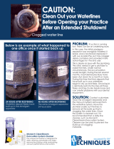
Figure 13. Acadia Amalgam Separator Assembly, PN A1350,
Alert Monitor Module Front Panel View
ACADIA MODEL WITH ALERT MONITOR
The Acadia Amalgam Separator Assembly, PN A1350, is available from Air Techniques with an Acadia Alert Monitor Module.
Acadia separators using this equipment have the ability to monitor the Solid Collection Filter of an Acadia from the utility room
or other convenient location such as the treatment operatory. It provides visual and audible indication when the collection lter
of the separator is nearly full of collected solid dental waste and needs replacement. If such a lter is not replaced, it would
result in improper filtering of amalgam and other dental waste and cause failure to pass an amalgam inspection.
Operator Controls & Indicators
Figure 13 shows Acadia Alert Monitor Module front panel controls and indicators while the table below lists each state of
the front panel STATUS LED Indicator and describes the corresponding condition. The Remote Panel Switch indicator
LED behaves the same way as listed below for the front panel STATUS LED except it will be extinguished instead of
Quick Flashing Green when the primary pump is off. Figure 14 shows the components provided in the Acadia Alert Monitor
Module Accessory Kit, P/N A1378.
PUMP ON/OFF
Switch
STATUS
LED Indicator
RESET Switch
Operation
Acadia models with the Acadia Alert Monitor Module automatically monitor the ll level of the Solid Collection Filter
and provides visual and audible indication when the collection lter is nearly full and requires replacement.
Bi-Color Panel Switch,
P/N 53202-1
Liquid Level Sensor
Cable, P/N A1344
Switch Ring, P/N
A1389
Wire Nuts, P/N 43303
Qty 4
Figure 14. Acadia Alert Monitor Module
Accessory Kit, P/N A1378

15
Installation Information
Installation of Acadia models with the Acadia Alert Monitor Modules require making the electrical connections required for
the associated vacuum system and connecting the Liquid Level Sensor Cable. The Acadia Alert Monitor Module has a flexible
design that allows it to meet the electrical requirements of specific installations. Power can be connected from the 24VAC
low voltage electrical box of the primary pump or via an optional 12 VDC power supply adapter (P/N A5135). A Bi-Color
Panel Switch is also included for remote system control and/or indication as desired. Install the the Acadia Alert Monitor
Module by performing the following procedures.
Electrical Connections
1. Refer to Figure 15 and access the connectors on the rear of the panel by removing the 4 nuts securing the Acadia
Alert monitor electronics enclosure to the panel.
2. Connect the module as shown by the view of Figure 16 corresponding to your particular installation requirements.
Make sure that the connected wires are positioned and held by the strain relief as shown by Figure 15.
View A shows the connections when using 24 VAC power, no Vacuum Equalizer and optional panel switch.
View B shows the connections when using 12 VDC power, no Vacuum Equalizer and optional panel switch.
View C shows the connections when using 24 VAC power, a Vacuum Equalizer and remote panel switch.
View D shows the connections when using 12 VDC power, a Vacuum Equalizer and remote panel switch..
3. Connect one end of the Liquid Level Sensor Cable to the Float Switch Connector J4 on the side of the module. Make
sure that the cable is positioned and held by the strain relief as shown by Figure 16.
Important: 1. Make sure that all connections are made, including the Liquid Level Sensor Cable to the Float Switch
Connector J4, prior to installing the Acadia Alert Monitor Panel Assembly onto the front enclosure
of the Amalgam Separator.
2. Gather connected wires together in a loose "S" and secure with the strain relief. See Figure 15.
4. Install the monitor electronics enclosure onto the panel and secure with 4 nuts removed in step 1.
5. Go to page 7 and complete the installation of the Acadia unit to the associated vacuum system.
ACADIA MODEL WITH ALERT MONITOR
Figure 15. Acadia Alert Monitor Panel Electronics Enclosure
J1 J3 J8 J5J7
J2
(Not Used)
Float Switch
Connector J4
Hex Nuts
(Qty 4)
Wiring Strain
Relief
Monitor Electronics
Enclosure
Wiring Strain
Relief

Figure 17. Acadia Alert Monitor Module Electrical Connection Configurations
Notes:
1. The Primary Pump must have its power circuit breakers left in the ON position to supply 24VAC low voltage power.
When an optional (P/N A5135) 12 volt DC power supply is used to power the Acadia Alert Monitor Module, clip off the plug end and connect the supply
wires to the #4 BRN and #2 YEL leads of connector J1. This connection is polarity insensitive.
2. The Vacuum Equalizer is optional equipment and purchased separately. The Vacuum Equalizer automatically regulates the facility vacuum level.
3. This connection re-routes primary pump control to the Vacuum Equalizer pump terminal block when the optional Vacuum Equalizer is installed.
4. All Pump connections are wired directly to Vacuum Equalizer in 12 VDC power configurations.
Figure 16. Typical Wire Routing Through Strain Reliefs
Gather connected wires
together in a loose "S" and
secure with the strain relief.
To Acadia Amalgam
Separator Liquid Level
Sensor Connector Jack
Important:
Always connect one end of the
Liquid Level Sensor Cable to the
Float Switch Connector J4 before
installing the module onto the
Acadia Amalgam Separator.
View A. Connections Using 24 VAC Power, No Vacuum Equalizer and
Optional Panel Switch
EQ SW TB
J5
J1 J3 J8 J7
1 1 111
EQ SW
LED SEL
VAC RMT
24 PW IN
NRO 3#
NRB 4#
LEY 2#
DER
NRO 3#
LEY 2#
NRB
J2
View B. Connections Using 12 VDC Power, No Vacuum Equalizer and
Optional Panel Switch
EQ SW TB
J5
J7
11
EQ SW
J2
J8
1LED SEL
RED
BRN
J3
1VAC RMT
J1
124 PW IN
BLK
BLK
To Optional Bi-Color Panel Switch for
indicator function only.
Tie YEL & ORN switch leads together.
To 12 VDC Power Supply
(See Note 1)
Connectors J7 & J5
Not Used
Connector J3
Not Used
View C. Connections Using 24 VAC Power, a Vacuum Equalizer
and Remote Panel Switch
EQ SW TB
J5
J1 J3 J8 J7
1 1 111
EQ SW
LED SEL
VAC RMT
24 PW IN
#3 ORN
#4 BRN
#2 YEL
RED
#3 ORN
#2 YEL
BRN
#3 ORN
#2 YEL
#4 BRN
#3 ORN
#2 YEL
J2
To Bi-Color Panel Switch
for Vacuum Equalizer
(See Note 2)
To Vacuum Equalizer Pump 1
Terminal Block. (See Notes 2 & 3)
To Primary Pump
24VAC Low Voltage
Electrical Box
(See Note 1)
To Vacuum Equalizer Control
Panel Switch Terminal Block
(See Notes 2 & 3)
View D. Connections Using 12 VDC Power, a Vacuum Equalizer
and Remote Panel Switch
EQ SW TB
J5
J1 J3 J8 J7
1 1 111
EQ SW
LED SEL
VAC RMT
24 PW IN
RED
BRN
#3 ORN
#2 YEL
#4 BRN
#3 ORN
#2 YEL
J2
BLK
BLK
To Bi-Color
Panel Switch for
Vacuum Equalizer
(See Note 2)
To 12 VDC Power
Supply (See Note 1)
To Vacuum Equalizer
Control Panel Switch
Terminal Block
(See Notes 2 & 3)
Connector
J3 Not Used
(See Note 4)
ACADIA MODEL WITH ALERT MONITOR
16
To Optional Bi-Color
Panel Switch
Connectors J7 & J5 Not
Used
To Primary Pump 24VAC Low
Voltage Electrical Box (See Note 1)

Figure 19. Acadia Amalgam Separator with Acadia Alert Monitor Module, PN A1350
Disposable Solid
Collection Filter,
P/N A1290
Amalgam Separator
Assembly
Liquid Level
Sensor Cable
Acadia Alert Monitor Module
Panel Assembly
Amalgam Separator
Chassis/Mounting Bracket
Acadia Alert Monitor Panel Assembly Installation
Refer to Figure 17 and install the Acadia Alert monitor panel assembly by performing the following steps..
1. Remove the 4 screws securing the existing cover plate (faceplate) to the separator front enclosure and remove the
plate. Make sure to save the 4 screws which are used to secure the Acadia Alert Monitor Panel Assembly.
Important: Make sure that all connections are made, including the Liquid Level Sensor Cable to the Float Switch Connector
J4, prior to installing the Acadia Alert Monitor Panel Assembly onto the front enclosure of the Amalgam
Separator.
2. Place the Acadia Alert Monitor Panel Assembly on the separator front enclosure and align the 4 screw holes of the
panel with the screw holes of the enclosure.
Important: Make sure not to disconnect wire connections to the panel.
3. Secure the panel to the front enclosure with the 4 screws removed in step 1.
4. Connect the unconnected end of the Liquid Level Sensor Cable to the Liquid Level Sensor Jack located on top of
the separator. Figure 18 shows the Acadia Amalgam Separator with the Acadia Alert Monitor Module installation
completed.
Figure 18. Acadia Alert Monitor Panel Assembly Installation and Liquid Level Sensor Cable Connection
Liquid Level
Sensor Jack
Liquid Level Sensor Cable -
Connect Between Float
Switch Connector (J4) &
Liquid Level Sensor Jack
Float Switch
Connector (J4)
Cover
Plate
ACADIA MODEL WITH ALERT MONITOR
17

This Air Techniques equipment is warranted to be free from defects in material and workmanship for a period of twenty-four
months from the date of installation by authorized Air Techniques Dealer service personnel.
Any item returned to our factory during the warranty period through an Authorized Dealer will be repaired or replaced
at our option at no charge provided that our inspection shall indicate it is defective. Dealer labor, shipping and handling
charges are not covered by this warranty.
This warranty does not apply to damage due to shipping, misuse, careless handling or repairs by non-authorized
service personnel. The warranty does not include the Solid Collection Filter Replacement. Warranty void if installed
or serviced by other than authorized service personnel. Air Techniques is not liable for indirect or consequential
damages or loss of any nature in connection with this equipment.
This warranty is in lieu of all other warranties expressed or implied. No representative or person is authorized to
assume for us any liability in connection with the sale of our equipment.
Quickly and easily register your new In-line Amalgam Separator on-line. Just have your product model and serial
numbers available. Then go to the Air Techniques web site, www.airtechniques.com, click the register a product
link and complete the registration form. This on-line registration ensures a record for the warranty period and helps
Air Techniques keep you informed of product updates and other valuable information.
WARRANTY
ON-LINE WARRANTY REGISTRATION
IF YOU NEED ASSISTANCE
TROUBLESHOOTING
Problem Possible Cause Solution
Low suction or
No suction.
a. Large Particle Inlet Filter Strainer clogged.
b. Disposable Solid Collection Filter lled.
c. Check that the input and output line
connections to the Separator are
tight. Make sure that there is no
clogs or kinking collapsing.
a. Clean Inlet Filter Strainer.
b. Replace the Solid Collection Filter.
Call your authorized dealer if necessary.
c. Call your authorized dealer for repair service if
faulty connections are found.
The Acadia Amalgam Separator requires minimal maintenance. The only maintenance requirements include:
Checking the Large Particle Inlet Filter Strainer for any blockages and cleaning as necessary.
Checking the ll level of Solid Collection Filter and replacing as necessary.
Replacing the Solid Collection Filter 12 months (one year) from the date of installation.
MAINTENANCE
Air Techniques Vacuum systems and accessories are designed and manufactured to high standards to deliver high-
quality performance. If any diculties are encountered with this product, please contact Air Techniques Technical Sup-
port as follows:
Headquarters:
1295 Walt Whitman Road, Melville, New York 1 I 747- 3 062
Phone: 800-247-8324 • Fax: 1-888-247-8481
Website: www.airtechniques.com
18

NOTES
19

© 2010 Air Techniques, Inc. • PN A1301 Rev. L • May 2021
Digital Imaging
• Digital Radiography
• Intraoral Camera
• Caries Detection Aid
• Intraoral X-ray
• Film Processors
Utility Room
• Dry Vacuums
• Wet Vacuums
• Air Compressors
• Amalgam Separator
• Utility Accessories
• Utility Packages
Merchandise
• Evacuation System Cleaner
• Imaging Accessories
• Chemistry
• Processor Accessories
For over 50 years, Air Techniques has been a leading innovator and manufacturer of dental
products. Our priority is ensuring complete satisfaction by manufacturing reliable products
and providing excellent customer and technical support. Whether the need is digital imaging,
utility room equipment or merchandise, Air Techniques can provide the solution via our network
of authorized professional dealers. Proudly designed, tested and manufactured in the U.S., our
products are helping dental professionals take their practices to the next level.
Air Techniques’ family of quality products for the dental professional include:
Corporate Headquarters
1295 Walt Whitman Road | Melville, New York 11747- 3062
Phone: 800-247-8324 | Fax: 888-247-8481
www.airtechniques.com
/