Page is loading ...

We Make Radiant Simple
Infloorboard Application
& Installation Guide
America’s Authority on Radiant Heating Systems and Designs for over 30 years

Chapter 1: Introduction …………………………………………………………………………………………….………………………..
History of Radiant Heating………………….….………….…….…….….…….….……………….…….…………
How it Works….………….………….…………………….….….….….….……….….………………...……..….…..
Advantages of using Infloorboard…………………….….…….…….…...…………………………………….
Chapter 2: Design and Performance……………………………………………………………………..……………….……………
Flooring R-Values…………….….…..…….………….….…….….….….………….……………………………..….
System Output………….………….….…………….……….….…….….….………….…………….………………….
Importance of having a LoopCAD Design Layout.….….….……………….……….…….…..……………
Estimating Required Number of Infloorboard Boards…….….…………………….……..….…..……..
Tubing and Loop Lengths….…………….………….….……..….….…….………….….….…….………..….….
Chapter 3: Installation………………………………………………………………………………….………….………………..………..
Understanding the Product and Components….……….….………….….….….…….……..………….
How to Space the Boards…………….….….…….….….…….…….………………..…….…….……….……….
Aligning and Attaching the Boards……………….….……….……….…….….…………………….….……..
Subfloor Requirements: Wood Subfloors…….………….….…….….……….…….……………….………
Equipment for Installation over Wood Subfloors…………….….…….….……….………..…………….
Installing Tubing in Grooves…….…………………….……….….…….….……………..………….…………….
Example Layout and Installation…….………………..…….….…….….…………….…………..…………….
Connections at the Manifold…….………….….…….…………………...……………..……………………….
Infloorboard Installation over Wood Subfloors…….………….….…….….……….……….…………….
Carpet and Vinyl over Infloorboard - Wood Subfloors…….………….….…….….…………..……….
Thin-set Tile or Stone over Infloorboard - Wood Subfloors…….……………….…….…………….
Mortar-set Tile or Stone over Infloorboard - Wood Subfloors…….………….…………………….
Laminate and Engineered Wood over Infloorboard - Wood Subfloors…………….….…………
Hardwood over Infloorboard - Wood Subfloors…….……………………………………….….…………
Other Application Options (Including Ceiling and Walls) …….………………..…….….…….…….
Installing Infloorboard over Concrete - Important Cautions…...……………..…….….……………
Flooring (except Strip Wood) over Infloorboard - Concrete Subfloor……………..…….………
Strip Wood Flooring over Infloorboard - Concrete Subfloor…...……………..………….…………
Infloorboard Cautions and Limitations…...……………..………………………………………….…………
Chapter 4: Design Services ………………………………………………………………….………………………………………………
Advantages of having a System Designed by Infloor ……….….…….….…….….….….…………….
Benefits for the Owner..….….…………….…….……………………………………………………...….….……
Benefits for the Architect, Designer, and Installer……………….….……….….….……….…….……..
Sample LoopCAD Layouts for Infloorboard….…….…………….…………….…………..……….………….
Table of Contents
page 2 | Table of Contents
3
3
3
5
6
6
7
7
8
8
10
10
11
12
14
15
16
17
18
19
20
21
22
23
24
26
28
29
30
31
32
32
32
33
34
www.infloor.com
Installer Caution:
This manual is deemed to be current at the time of publication. It is the installer's responsibility to install according to the most current
Application Guide. This guide does not purport to address all relevant issues; it assumes a knowledge of good practice in both hydronics and
construction methods. Installers should always consult all relevant local, regional and national codes, and adhere to good construction
practice. Infloorboard™ should only be installed by knowledgeable qualified installers. Infloorboard™ installations frequently require the
coordination of trades. These are, most typically, mechanical and flooring trades. Any issues regarding this coordination should be worked out
in advance. Failure to follow the instructions of this guide, failure to adhere to relevant local, regional and national codes, failure to coordinate
trades and failure to follow good construction practice may cause an unsatisfactory result. See also "limitations of use" elsewhere in this
publication. The limitations and instructions of use for PEX pipe and other hydronic components provided by the manufacturers shall also be
referenced and followed during installation; this manual does not address many aspects of a hydronic installation.
INFLOORBOARD™ APPLICATION AND INSTALLATION MANUAL © JANARY 2017, VERSION 5. INFLOORBOARD™ IS SOLD UNDER LICENSE FROM
WARM BROTHERS INC. U.S. PATENT #6,533,185 AND OTHER PATENTS PENDING.

Introduction | page 3
Infloorboard Application & Installation Guide
Introduction
Welcome to the world of Infloor Heating Systems®.
We specialize in designing and providing the best
radiant heating systems and solutions available.
We are an industry pioneer with over 30 years of
experience and extensive knowledge about radiant
heating methods, applications, and designs. Our
heating solutions combine superior performance,
comfort, and energy-efficiency. We make radiant
simple!
We created this comprehensive application and
installation guide to help provide all the
information you need to select, design, install, and
start-up our premier product, Infloorboard.
With Infloorboard, the hydronic radiant heating
that everyone loves, is now more efficient, more
responsive, and compatible with standard
construction practices. Ideal for new construction
and remodeling alike: low profile, light weight, and
rapid response. Infloorboard delivers a genuine
advance in the best heating system you can buy...
hydronic radiant heat.
Infloor residential system components may be
used for space heating or warm floor applications.
An Infloor representative is also available to
answer questions and provide additional support.
History of Radiant Heating
The concept of "radiant floor heating" or under-
floor heating has been used for centuries. It can be
traced back to the Romans who used a hypocaust,
which was a system that heated homes with hot air
under the floors. Under-floor radiant heating also
has a long history throughout Asia.
Heating by radiant energy is observed every day;
the warmth of the sunshine being the most
common example. It is similar to the heat you feel
when you stand by a window on a sunny cold day.
Your face feels warm, but the sun didn't need to
heat the air outside to make you feel that way.
Under-floor heating serves up heat from below.
The result is a more even overall heat that warms
everything in the room, including surfaces,
furnishings, and, most importantly, you. The
systems depend largely on radiant heat transfer;
the delivery of heat directly from a warm surface to
the people and objects around it.
Why It Works So Well
Non-structural Infloorboard™ is designed
specifically for subfloor applications. Infloorboard™
is constructed of a dense composite board covered
with aluminum that spreads the heat evenly and
quickly from the hydronic tubing. Infloorboard™
heats rapidly and is easy to control with setback
thermostats for maximum energy efficiency. It
contains just enough thermal mass to be effective,
but not so much that it's difficult to control. No

other product offers this combination of
performance, ease of installation, and cost-
effectiveness.
Infloorboard™ is typically glued and screwed, or
stapled to a wood subfloor. Then PEX pipe, which
will carry warm water, is snapped into the groove.
Heat is transferred from the pipe to the aluminum
and the board. Infloorboard™ is manufactured
from MDF (medium density fiber board), which are
relatively conductive wood products weighing 44-
50 lbs. per cubic foot. The board is grooved and
then laminated with a top layer of highly
conductive aluminum to efficiently disperse and
transfer heat away from the groove to the surface
area of the whole board.
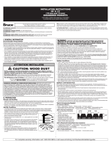
Acceleration
Acceleration is a measure of how fast a radiant
heating system responds. Aluminum is
approximately 1,000 times more conductive than
wood. The layer of aluminum on Infloorboard™
and in the groove significantly enhances both the
transfer of heat and evenness of heat distribution
of the board. See Illustration A-1 to see how the
heat transfers through Infloorboard™. The thin
profile and relatively high density contributes to
the superior acceleration and deceleration of
Infloorboard™.
Traditional radiant heating systems in concrete
work well, but they must first charge a large
thermal mass before heat will begin to radiate
from the panel. They accelerate and decelerate
very slowly due to the large thermal mass, and
they can be hard to control. Infloorboard™, being
thin, but relatively dense, and aided by its
conductive aluminum layer, responds very rapidly.
This results in greatly improved response time,
with almost no overheating since there is almost
no "thermal lag" to overcome. Infloorboard™ can
be controlled with standard set-back thermostats.
INFLOORBOARD™ WARMCOAT
The Infloorboard™ Warmcoat aluminum top layer
provides multiple benefits. It is highly conductive.
This Warmcoat aluminum layer is also moisture
resistant. When the edges and grooves of the
Infloorboard™ boards are sealed using silicone
caulking, it provides significant moisture protection
for the board. And it provides a barrier to the
transmission of any outgassing from the board.
Infloorboard™ is manufactured to meet the Federal
Housing Authority (FHA) outgassing standard of
less than 0.3 ppm of formaldehyde. Independent
laboratory tests with 144°F water indicate that,
due to the aluminum Warmcoat layer,
Infloorboard™ has virtually no detectable levels of
outgassing.
Introduction
page 4 | Chapter 1 - Introduction www.infloor.com
Quick Response
● Low profile, light weight for easy installation
● Avoid the moisture, weight and mess of gypsum
cement or concrete
● Radiant installations, big or small, can be easily
scheduled with no lost time for concrete curing
Illustration A-1

Introduction | page 4
Introduction
Chapter 1 - Introduction | page 5
Infloorboard Application & Installation Guide
ADVANTAGES OF INFLOORBOARD™
Hydronic radiant heating is the most comfortable
and efficient way to heat your home or building,
with numerous construction benefits and
unsurpassed flexibility in zoning. For many years,
typical applications for radiant systems involved
embedding tubing in concrete slabs or pouring
"lightweight concrete" over tubing stapled to
subfloors.
The lack of good alternatives to these types of
systems permitted designers to overlook the
limitations and disadvantages of concrete systems.
Infloorboard™ provides that alternative. It is
designed for the application of hydronic radiant
tubing over a variety of construction types.
Infloorboard™ may be used in new construction and
is also advantageous in the growing retrofit market.
While only adding 5/8" to the existing floor height,
Infloorboard™ provides a superior performing
radiant heating system. In addition, application of
the system is made easy because only three types of
pieces are required for installation.
Construction Friendly
Infloorboard™ avoids joist upsizing, double plating
and hardwood nailing strips associated with
gypsum-based concrete radiant heating systems.
Also, Infloorboard™ eliminates substantial drying
costs required by moisture laden concrete and
gypsum-based cement. Time is money.
Infloorboard™ eliminates scheduling and curing
delays.
Cost Friendly
Infloorboard™ is installed using conventional
construction practices and commonly used tools.
With a layout plan, the three Infloorboard™ panel
patterns can be systematically arranged on the
subfloor. Not only are the boards light weight --
they're also easy to handle, cut and attach.
Flooring Friendly
Infloorboard™ provides a quality flat surface for
floor covering assemblies. Each of these flooring
assemblies is supported by detailed drawings and
instructions such as those illustrated in our
application guide.
●Hardwood
●Engineered Wood
●Tile/Stone
●Carpet
●Vinyl/Resilient Flooring
●Laminate
Planet Friendly / Green Product
Infloorboard™ is made with Green Cross Certified
Medium Density Fiberboard (MDF), which is
manufactured with recycled wood products. The
glue is a zero VOC, and the aluminum layer may be
recycled. The MDF used in Infloorboard™ has less
than HUD minimum Formaldehyde content, and the
aluminum layer is a positive barrier to outgassing of
formaldehyde. A report by Environmental Analysis
Incorporated has provided independent testing of
this in real-life heating conditions.
Hardwood over Infloorboard

page 6 | Chapter 2 - Design & Performance
HEAT LOSS ANALYSIS AND SYSTEM DESIGN
Systematic heat loss and design for the structure to
be heated should be done prior to any
Infloorboard™ installation. As with all floor heating
jobs, a detailed and accurate heat loss must be
calculated in order to determine proper design
conditions. This may be provided by a design
service (see Design Services pages). Refer to the
1999 Radiant Panel Association Guidelines for the
Installation of Radiant Panel Systems for standards
on insulation and heat loss.
Designer’s Note
Perform the heat loss analysis of the structure at the
design stage. This way, selection of floor coverings can
be made with the system requirements in mind. If the
heat loss is too high, add insulation or auxiliary heat. In
a very high heat loss room, Infloorboard™ can be added
to the walls or ceilings for extra heat.
R-VALUE OF FLOOR ASSEMBLIES
While Infloorboard™ will work with a wide variety
of floor coverings over the top of the boards, it is
important to realize that all floor coverings offer a
resistance to heat transfer typically measured by
their R-Value. As with all radiant systems, the
higher the R-Value of the floor covering, the higher
the average water temperature it takes to
overcome this resistance and to generate the
desired amount of heat. If the R-value of any
covering on top of Infloorboard™ is excessive, as
with any radiant heating system, performance will
be compromised due to lack of heat transfer, or
would require exceeding the 150°F maximum
supply water temperature. The maximum
recommended supply water temperature for
Infloorboard™ is 150°F.
Designer’s Note
Remember average water temperature means the
average of the supply and return water temperatures
flowing to and from the loop. Most typically,
Infloorboard™ is designed with a 20°F temperature
drop. This means the supply water temperature would
typically be 10°F higher than the average water
temperature.
Design & Performance
www.infloor.com
Illustration A-2: Account for all heat losses of the building
Illustration A-3: Always account for the resistance of floor
coverings

Chapter 2 - Design & Performance | page 7
Infloorboard Application & Installation Guide
Design & Performance
SYSTEM OUTPUT
Chart C-1, can be used to estimate system output
with different floor coverings. This chart shows the
steady state performance of Infloorboard™. To the
left are the BTU/Sq. Ft/Hour. The diagonal lines
represent the resistance of the floor coverings on
top of Infloorboard™. Along the bottom is the
average water temperature required to achieve the
output. The chart is read by selecting the correct
BTU requirement and then moving horizontally
until you find the line indicating the correct R-Value
of the floor assembly on top of Infloorboard™. At
that point, drop down vertically to see average
water temperature. See the chart above for a list of
estimated floor covering R-Values.
Designer’s Note
Learn about the resistance of intended floor coverings at
the design stage and make sure they are within the
requirements of the system. Realize also that your
calculation should include the resistance of the whole
flooring assembly above the Infloorboard™. If you are
unfamiliar with hydronic design, good practice and the
physics of hydronic heat transfer, you should not design
an Infloorboard™ system. Consult your Infloorboard™
distributor for assistance and referral to third party
design services.
LOOPCAD LAYOUT AND DESIGN SERVICES
Third party services can provide complete system
design and CAD layouts for Infloorboard™
installation. Contact your Infloorboard™ distributor
for details. All Infloorboard™ systems should be
installed by qualified installers.
Floor Covering R-Value
1/2" Oak Parquet and Pad 0.7
3/8" Hardwood 0.5
48 oz. Waffled Sponge Rubber 0.8
5/8" Oak Wood 0.6
Asphalt Tile 0.1
Bare Concrete - No Covering 0
1/2" Bonded Urethane 2.1
Heavy Carpet 0.8
Heavy Carpet with Heavy Pad 1.9
Heavy Carpet with Light Pad 1.6
Heavy Carpet with Rubber Pad 1.2
Light Carpet 0.6
Light Carpet with Heavy Pad 1.7
Light Carpet with Light Pad 1.4
Light Carpet with Rubber Pad 1
Linoleum 0.1
Marble Floor and Mudset 0.2
3/8" Prime Urethane Underlayment 1.6
Rubber Pad 0.6
Rubber Tile 0.1
All R-values shown in hr*ft2F/btu
R-VALUES OF VARIOUS FLOOR COVERINGS

page 8 | Chapter 2 - Design & Performance
ESTIMATING THE REQUIRED NUMBER OF BOARDS
For simple and fast installation, it is highly
recommended that a full Infloorboard™ layout be
used, indicating the precise panel and tubing
layout. A full plan is recommended for the first few
jobs. Contact your Infloorboard™ distributor about
getting a layout and a design. The following
calculations can be used for estimating the
required number of boards. For experienced
installers, calculate the net square footage of each
room and multiply by the following factors:
Straight - 0.133
Utility - 0.028
Combo End - 0.028
Example: For a 600 Sq. ft. room, multiplying 600 by
0.133 gives approximately 80 straight boards.
Multiplying 600 by 0.028 gives 17 Utility pieces.
Multiplying 600 by 0.028 gives 17 Combo end
pieces. It is always recommended that an
additional 10% material excess be added to the
estimation.
TUBING AND LOOP LENGTHS
Infloorboard™ is designed for use with 3/8"
nominal ASTM F-876 PEX (cross-linked
polyethylene) and InfloorPERT® tubing, ASTM
F2623 for Polyethylene of Raised Temperature (PE-
RT), with an average outer diameter measuring 0.5
inch. Loops shall never be over 250 feet including
the leaders to the manifolds. For areas with heat
loss greater than 25 BTU/ sq.ft., loops shall never
be over 200 ft. This is due to high pressure drops
and water velocity, as shown in the following chart
C-2* (grayed area over 25 BTU/Sq. Ft). Friction
losses in the chart are approximate; actual friction
losses depend on fluid viscosity and temperature.
*The shaded area in the 250' loop chart C-2 on the
following page indicates a high pressure drop. It is
recommended to use the shorter 200' loop length
in this case, as shown in the second chart. Once the
room square footage is determined, multiply the
total by 1.5. Example: For a 600 sq.ft. room,
multiplying 600 by 1.5 gives 900 lineal feet of 3/8"
PEX tubing. This room would require 4 loops at 225
ft. each. Alternatively, three 250 foot loops and one
150 foot loop could be used, provided that the flow
to the different loops is balanced by using, and
adjusting correctly, balancing valves on each loop.
Notice Loop Lengths
● Notice that loop lengths should never be over
250', for heat loss areas over 25 BTU/ sq.ft., loop
lengths should not be over 200'
● Since the tubing is 8" on center, a 250' loop will
cover a maximum of 166 sq.ft. A 200' loop will
cover a maximum of 133 sq.ft. Remember to
allow for the length to the manifolds
Design & Performance
www.infloor.com

Infloor SNOWMELT Installation Guide Introduction | page 4
Infloorboard Application & Installation Guide
Design & Performance
Chapter 2 - Design & Performance | page 9
BTU/SQ/FT
10
15
20
25
30
35
40
Friction Loss (Ft. Head)
2.22
4.7
8.01
12.1
16.96
22.8
28.87
Water Speed (Ft./Second)
0.6
0.9
1.2
1.5
1.8
2.1
2.4
GPM Per Loop
0.18
0.27
0.36
0.45
0.54
0.63
0.72
BTU/SQ/FT
10
15
20
25
30
35
40
Friction Loss (Ft. Head)
0.98
2.07
3.53
5.33
7.47
9.93
12.72
Water Speed (Ft./Second)
0.45
0.68
0.9
1.13
1.35
1.58
1.8
GPM Per Loop
0.14
0.2
0.27
0.34
0.41
0.47
0.54
INFLOORBOARD™ 250' LOOPS 20°F TEMP DROP CHART
INFLOORBOARD™ 200' LOOPS 20°F TEMP DROP CHART
Designer’s Note
Remember average water temperature means the average of the supply and return water temperatures
flowing to and from the loop. Most typically Infloorboard™ is designed with a 20°F temperature drop. This
means the supply water temperature would typically be 10°F higher than the average water temperature.
*Shaded areas have high head loss

UNDERSTAND THE PRODUCT
COMPONENTS
Infloorboard™ comes in three (3) different board
configurations: Straight,Utility End, and Combo End.
They are assembled to make a channel for the pipe.
Each piece measures 16" x 48". The grooves are
centered 8" apart. Infloorboard boards cut easily
with a circular saw.
page 10 | Chapter 3 - Installation
Installation
www.infloor.com
STRAIGHT
These are used about 70% of the time
UTILITY END
These are used when only a return is
needed, usually about 15% of the time
COMBO END
These are used when a return and an extra
channel are needed, usually, about 15% of
the time
Always Plan Ahead
●Carefully read and follow the installation
instructions
●Familiarize yourself with the materials and
installation methods before you start
●Use and follow a CAD layout, particularly if
you are a first time installer

Infloorboard Application & Installation Guide
Installation
PRODUCT SHIPPING INFORMATION
Nominal dimensions: Each board is 16" x 48" x 5/8"
thick, or 5.333 square feet a board Weight:
Approximately 2.5 lbs. per square foot, 13.3 lbs.
per board Pallet Size: 4' x 4' x 24" tall (Three (3)
Infloorboards to a row, 33 rows high)
Approximate Pallet Weight: 1317 lbs.
Approximate Truckload Quantities: 16,885.44
square feet, or 33 pallets, 42,214 lbs.
Pallet Appearance: Shrink wrapped, corner
protected, color coded corners by part #
Recommended Product Mix: Straight 70%, combo
end 15%, utility 15%; allow 10% extra for waste.
INSTRUCTIONS FOR PROPER STORAGE AND
MOISTURE CONTACT
Infloorboard™ should always be stored in a
temperate, dry place (40°F-90°F). Avoid prolonged
exposure to sunlight. Do not store in a damp
location. Be sure to follow all instructions
elsewhere in this manual regarding protecting the
board from prolonged moisture contact. If these
instructions are not followed, expansion of greater
magnitude could create undesirable effects.
UNDERSTAND HOW TO SPACE THE BOARDS
The actual width of each board is 15 7/8", which
provides for installing the boards with a slight gap
in between boards, to allow for expansion at
different temperatures and for normal variances in
humidity in a finished home. When aligning
straights with the combo ends or utility ends using
a piece of tubing, as shown in the following
section, a slight gap of approximately 1/16" will
naturally occur between the straight boards. This is
normal. Try to allow a similar 1/16" inch gap
between the ends of all boards, but always make
sure all grooves align, as described in the following
section.
Installer’s Note
MAKE SURE CUT BOARDS ARE ACCURATELY CUT
Since Infloorboard™ is a modular system, the
boards are manufactured to tight tolerances in
groove spacing and squareness of the sides and
ends. When cutting Infloorboard™, make sure to
cut them squarely and align them carefully so that
subsequent pieces will fit correctly. This is not
difficult, but attention to this easy step will prevent
major problems.
Chapter 3 - Installation | page 11

page 12 | Chapter 3 - Installation
HOW TO ALIGN THE GROOVES CORRECTLY
The easiest way to assure
the grooves for the pipe are
correctly aligned between
boards is to cut 6" pieces of
3/8" tubing and use them as
alignment tools. To do this,
get the boards close to the desired alignment and
press a piece of tubing in each groove, lapping 3"
into the groove of each board, as shown below.
After the board is attached, these should be
removed.
ATTACHING INFLOORBOARD™ TO A SUBFLOOR:
GLUING PATTERNS
Each Infloorboard™ should be glued to a wooden
subfloor using construction adhesive type glue at a
minimum 1/8" bead in the gluing pattern below.
Every board should be glued.
Tips for Gluing
The glue may be applied to
the underside of the board
or to the floor. Avoid
getting glue in the groove
or where it may come in
contact with the tubing.
Many glues can damage
PEX tubing.
Installation
www.infloor.com
Glue Pattern

Chapter 3 - Installation | page 13
Infloorboard Application & Installation Guide
Installation
AFTER GLUING, SCREW OR CROSS STAPLE BOARDS
TO SUBFLOOR
After you have glued the Infloorboards, the boards
should be screwed to the subfloor. On full size
pieces (16"x48"), ten screws should be used, 8 on
the perimeter and 2 in the middle, or as a general
rule, 16" O.C. for the perimeter and 24" O.C. for
the interior. This pattern is shown below. As an
alternative to gluing and screwing, Infloorboard™
may be installed by gluing and stapling, as shown
below. When installed with this method, it is very
important that the board is glued and stapled with
the same quantity of glue and staple points as
shown in the screwing pattern. The boards should
also be cross stapled as shown for extra strength.
Cross stapling means 2 staples are put closely
together at opposing 45° angles, as shown below.
Cross staple or screw the boards
down after gluing.
CROSS STAPLING INFLOORBOARD BOARDS NAILING OR CROSS STAPLING
PATTERN FOR INFLOORBOARD

OVERVIEW OF FLOOR SURFACE REQUIREMENTS
Note: See also the specific application drawings
and notes for installing Infloorboard™, on pages
that follow in this manual.
SUBFLOOR REQUIREMENTS GENERAL
The surface of the subfloor must be flat: The
requirement for flatness is defined as the
maximum difference between two adjacent high
points and the intermediate low point. The
maximum acceptable difference in level is 3/16 of
an inch in a 10-ft. radius.
Fill excessive voids or low areas using a leveling
compound: Allow the leveling compound to dry
thoroughly before beginning the installation. Check
with the leveling compound manufacturer to be
sure it is appropriate for the application. High areas
can be ground down or floated over with a self-
leveling compound. The surface of the floor must
be clean and dry.
SUBFLOOR REQUIREMENTS, WOOD SUBFLOORS
Wood subfloors must have a stable moisture
content, between 6 - 10%. Creaking subfloors must
be repaired before installation. If the subfloor sags,
inspect the joists below for twists or weakness. If
the subfloor is cupped or uneven at the joints,
recheck the moisture content of the subfloor to be
sure it is in the 6 - 10% range. Check for excessive
moisture in the crawl space or basement and look
for other signs of a potential water problem. High
areas are sanded or planed; low areas are patched
or filled with an appropriate leveling compound, or
covered with a rigid underlayment. When using a
leveling compound, be sure to follow the
manufacturer's recommendations, and allow the
compound to dry completely before starting to
install the floor.
Important Note
INFLOORBOARD™ AND CONCRETE SUBFLOORS
Infloorboard™ was designed to be installed over a
wooden subfloor. Installation over concrete has
been successfully done, but requires extreme care,
an assured dry slab and is not a preferred
application. Details for installation over concrete
are available upon request.
page 14 | Chapter 3 - Installation
Installation
www.infloor.com

EQUIPMENT REQUIRED FOR INSTALLATION OVER
WOODEN SUBFLOOR
The following is necessary for the installation of
Infloorboard™:
●Table or circular saw. A carbide blade is
recommended
●Electric or cordless drill gun with No. 2 Phillips
bit (if you are screwing down boards) and 5/8"
drill bit for supply and return bury points
●Sheathing type pneumatic stapler (if you are
cross stapling boards)
●Rubber or hard hide mallet
●Chalk line, marking pencils and square
●Vacuum cleaner to clean grooves prior to
installation
●6" pieces of 3/8" tubing for alignment of
grooves
●Tubing uncoiler is recommended for installing
tubing
Installer’s Note
CUTTING INFLOORBOARD™
Infloorboard™ cuts easily with a quality carbide
circular saw blade. Pieces frequently must be cut to
provide an accurate fit for each room. It is
important that they be cut squarely to keep the
alignment of grooves accurate in the installation. If
you are cutting a large number of boards for a
complicated space, number them and make a map
so you remember where they go.
Chapter 3 - Installation | page 15
Infloorboard Application & Installation Guide
Installation
1 2 3
4 5 6

page 16 | Chapter 3 - Installation
INSTALLING TUBING IN THE GROOVES
First, vacuum the
grooves so there is
nothing that will damage
the tubing or keep it
from going properly into
the groove. The use of a
tubing uncoiler is
recommended. Start at
the intended manifold
location and allow enough tubing as a "leader" to
attach the tubing to the manifold. You may then
begin, but make sure you understand the layout
and where and how you will return to the
manifold. There is, intentionally, a tight tolerance
between the PEX or PERT tubing and the slightly
undercut groove. This allows the tubing to be
retained in the grooves once it is pushed in place.
Usually, this only requires "walking the tubing into
the groove" as shown in the photographs below.
Occasionally tubing installation may require the
use of a rubber or hide mallet as shown on the
previous page to force the tubing in place in the
grooves. After installing a loop of tubing, always
walk the loop and make sure the tubing is fully in
the groove for the entire length of the groove. This
is very important! The top of the tubing should be
just below the level of the top of the
Infloorboard™, and fully retained in the groove.
Installer’s Note
INFLOORBOARD™ WARMCOAT™ METAL AND
GROOVES
Infloorboard™ has an aluminum Warmcoat™ metal
layer that is slit for the grooves. It is designed to be
folded down into the grooves and pressed to the
side as the tubing is pushed into the groove.
Installation
www.infloor.com

Chapter 3 - Installation | page 17
Infloorboard Application & Installation Guide
Installation
EXAMPLE LAYOUT AND INSTALLATION
INSTALLATION STEP 1
Utilizing a plan layout, determine panels needed and
tubing lengths required. Be sure to always use good
judgment in allowing enough tubing at ends for
leaders up to manifolds. A plan should indicate which
type of system will be implemented.
INSTALLATION STEP 2
Begin the Infloorboard™ layout by starting at the
beginning of the supply run into the space and
running board along the perimeter of the heated
space to the area of highest heat loss.
INSTALLATION STEP 3
Add end pieces and straight pieces, working your
way back away from the area of heat loss. Once all
boards are in place, drill holes (subfloor with access
application) or route leader back to manifold via
custom grooves or grout (slab or existing subfloor
application) for supply and return leaders to
manifolds.
INSTALLATION STEP 4
Feed enough supply tubing to route to manifold
through drilled supply hole below the floor or before
the start of groove (if groove goes directly to
manifold). Tubing may then be "popped" into
grooves after all grooves have been thoroughly
cleaned with a vacuum cleaner. Once tubing has
been routed back to the return location, cut enough
to route to return manifold.
SPECIAL COVERAGE AREAS
In areas of special coverage, such as shower basins
using tile grout as a base, tubing may be routed to
and from Infloorboard™ in order to accommodate
desired coverage.

page 18 | Chapter 3 - Installation
Installation
www.infloor.com
CONNECTIONS AT MANIFOLD
Manifolds are usually located in a space with an
access panel, near the heating zone they serve, in
places like in the back of a closet. The tubing may
be routed to the manifold in four ways:
1) Insert tubing directly in the grooves, which
works with few loops ending adjacent to the
manifold location.
2) Drill holes, dive the tubing under the floor and
bring it up again at the manifold.
3) Place solid MDF sheet next to the manifold into
which supply and return lines are custom routed to
the grooves of the Infloorboard™.
4) Or, tubing may be run out of the Infloorboard™,
stapled to the subfloor and routed directly to the
manifold. A grout may then be used to cover the
tubing and level it to the Infloorboard™. If needed,
sleepers are placed in between tubing to provide a
nailing or screwing base for floor coverings. Use
nailing plates as necessary to protect tubing from
damage. Depending on how many circuits are on a
given manifold various sizes of sheets or grouting
area are required.

Chapter 3 - Installation | page 19
Infloorboard Application & Installation Guide
Installation
INFLOORBOARD™ INSTALLED OVER WOOD
SUBFLOOR
GENERAL INSTALLATION REQUIREMENTS FOR ALL
FLOORING OVER WOOD SUBFLOOR
1) Do not install Infloorboard™ without an accurate
room-by-room heat loss analysis of the structure to
be heated and a design/layout for Infloorboard™
that takes into account the resistance and heat
transfer of the actual floor coverings. If
Infloorboard™ cannot provide all the necessary
heat, make provisions for additional back up heat.
2) Thoroughly clean all surfaces that Infloorboard™
will be applied to. The surface to which
Infloorboard™ will be attached must be flat and dry
prior to installation. See requirements for flatness
and moisture. The requirement for flatness is
defined as the maximum difference between two
adjacent high points and the intermediate low
point. The maximum acceptable difference in level
is 3/16 of an inch in a 10-ft. radius. Wood subfloors
must have a stable moisture content between 6 -
10%. Creaking subfloors must be repaired before
installation. If the subfloor sags, inspect the joists
below for twists or weakness. If the subfloor is
cupped or uneven at the joints, recheck the
moisture content of the subfloor to be sure it is in
the 6 - 10% range. Check for excessive moisture in
the crawl space or basement and look for other
signs of a potential water problem. High areas
should be sanded or planed, low areas patched or
filled with an appropriate leveling compound, or
covered with a rigid underlayment. When using a
leveling compound, be sure to follow the
manufacturer's recommendations, and allow the
compound to dry completely before starting to
install the floor.
3) Chalk lines of a square reference point, as walls
may out of square.
4) Lay out boards according to the plan.
5) Secure boards with construction adhesive to the
wooden subfloor. Be sure to use adequate
adhesive and follow the recommended pattern.
6) Start layout of all pieces by securing a corner to
allow for proper alignment.
7) Use 6" lengths of tubing in the grooves, lapping
3" into each board to help align the grooves of the
boards.
8) A 1/16" width space shall be used between
boards.
9) After gluing boards in place, drill and screw or
cross staple Infloorboards to subfloor, according to
recommended pattern.
10) Once all boards are installed, clean out all
grooves with a vacuum.
11) Snap tubing into groove and route to manifold
per plan.
12) Follow specific extra recommendations for
each floor covering, and refer to the complete
installation manual for further instructions on the
installation of the Infloorboard™ system.

page 20 | Chapter 3 - Installation
Installation
www.infloor.com
CARPET OVER INFLOORBOARD™
Infloorboard™ shall be installed over a wooden
subfloor, complying with "General Infloorboard™
Installation Requirements For All Flooring Over Wood
Subfloor". In addition, the following specific cautions
and instructions shall be followed: Carpet and pad
may be installed over Infloorboard™. When installing
the pad, care should be taken to avoid puncturing
tubing. It is advised that a thin layer of underlayment
plywood be applied over Infloorboard™ prior to
carpet and pad installation to protect tubing from
point loads. As with all radiant heating installations, a
thin slab foam rubber pad and short, high density
carpet should be used. If carpet pad is glued, a high
temperature latex adhesive must be applied. Glue to
underlayment plywood: do not glue to Infloorboard™
or to tubing! Maintain 2" minimum tubing clearance
from carpet tack strips.
VINYL OVER INFLOORBOARD™
Infloorboard™ shall be installed over a wooden
subfloor, complying with "General Infloorboard™
Installation Requirements For All Flooring Over Wood
Subfloor". In addition, the following specific cautions
and instructions shall be followed: When installing
vinyl flooring, it is required that a thin layer of
underlayment plywood be applied over
Infloorboard™. In wet locations, a sealant layer
should be added. Underlayment plywood that has a
grid printed on it helps locate tubing runs and
prevent puncturing the tubing when the plywood is
being screwed to the Infloorboard™. In the case of
vinyl, use underlayment, filler and glues suggested by
the manufacturer for use over radiant heat. Most
vinyl flooring is manufactured to an ASTM standard
with an upper limit of floor temperatures of 85°F.
This limit should be followed. Attach required
underlayment with care to not puncture tubing.
/