Page is loading ...

Construction
Automotive
Industry
www.rehau.com
REHAU RADIANT HEATING SYSTEMS
DESIGN GUIDE

2
TABLE OF CONTENTS
1. . . . . . Scope ......................................3
2. . . . . . Design Considerations .........................4
3. . . . . . System Overview .............................5
3.1 . . . . Applications ..................................5
3.2 . . . . Thermal Comfort ...............................5
3.3 . . . . Energy Efciency ..............................6
3.4 . . . . Thermal Zoning ...............................6
3.5 . . . . Construction Methods ...........................6
4. . . . . . System Components. . . . . . . . . . . . . . . . . . . . . . . . . . .7
4.1 . . . . Pipes .......................................7
4.2 . . . . Fittings - Compression-sleeve ....................24
4.3 . . . . Fittings - Compression Nut ......................25
4.4 . . . . Manifolds ...................................26
4.5 . . . . Heat Transfer Panels ...........................26
4.6 . . . . Heat Transfer Plates ...........................27
4.7 . . . . Installation Accessories .........................27
5. . . . . . System Planning .............................28
5.1 . . . . Building Layout ..............................28
5.2 . . . . Building Heat Loss ...........................28
5.3 . . . . Room and Building Temperatures .............. 28
5.4 . . . . Building Zoning ..............................29
5.5 . . . . Insulation ..................................29
5.6 . . . . Floor Coverings ...............................29
5.7 . . . . Wet Construction Joints .........................31
5.8 . . . . Heat Source .................................32
5.9 . . . . Heating Water Controls .........................33
5.10 . . . Manifolds ...................................34
5.11 . . . Circulator Pumps .............................34
6. . . . . .System Design. . . . . . . . . . . . . . . . . . . . . . . . . . . . . . .36
6.1.....Step 1 - Gather Documents and Specs ..............36
6.2.....Step 2 - Determine Heat Output ...................36
6.3.....Step 3 - Determine Surface Temps .................36
6.4.....Step 4 - Check Temperature Limitations .............36
6.5.....Step 5 - Select Construction Method ................37
6.6.....Step 6 - Select Pipe Size ........................40
6.7.....Step 7 - Select Pipe Spacing .....................40
6.8.....Step 8 - Determine Pipe Length ...................41
6.9.....Step 9 - Calculate Heating Water Temp ..............41
6.10....Step 10 - Calculate Heating Water Flow .............42
6.11....Step 11 - Size Manifold .........................42
6.12....Step 12 - Locate Manifold .......................42
6.13....Step 13 - Layout Pipe ..........................44
7. . . . . .System Testing ..............................45
For updates to this publication and the most current technical instructions, safety information and manufacturer’s recommendations, visit na.rehau.com/resourcecenter

3
1. SCOPE
This technical information applies to the planning, installation
and connection of REHAU radiant heating systems using PEXa
crosslinked polyethylene pipe.
Persons using this guide must be experienced and appropriately
licensed hydronic heating system designers, who have an understand-
ing of the principles and practices for system design and installation.
The information presented in this guide is intended to demonstrate
general methods and is not specic to your project conditions. It is
the responsibility of the designer to check the prevailing local codes
and to verify that technical information presented in this guide is ap-
propriate for a particular installation. This guide does not supersede
the recommendations of other manufacturers. If there is conicting
information, the designer must consult with the other manufacturer's
representative prior to planning, installing and connecting the radiant
heating system.
After reading this guide, designers should attend the Skill Builders
seminar offered by the REHAU Academy, where design techniques
for radiant heating systems are more fully explored. Designers should
also periodically check the REHAU Resource Center for the latest
updates.
This guide should be used in conjunction with the REHAU Sustain-
able Building Technology Product Catalog which provides a detailed
description of each system component and the REHAU Radiant Heat-
ing Installation Guide which provides guidelines for system installation.
The designer should also review the REHAU PEXa Limited Warranty
and pertinent supplemental REHAU Technical Bulletins before begin-
ning to design a radiant heating system.
Heat loss calculation methods are not covered. This guide assumes
the designer has already calculated the building heat loss using an
approved standard or equivalent engineering calculation.
If you do not have prior experience with hydronic heating systems or
require additional assistance, please contact your regional REHAU
sales ofce.
This symbol and the signal words DANGER, WARNING or
CAUTION alert you to personal injury hazards. If you don’t avoid
the hazardous situation:
– DANGER! Will result in death or serious injury
– WARNING! Could result in death or serious injury
– CAUTION! Can result in minor or moderate injury
The signal word NOTICE is used to help you avoid property dam-
age. We cannot warn of all hazards; you must also use your own
good judgment.

4
The most critical points in a radiant system design are:
− To consider the impact of the radiant oor construction methods
to avoid problems during installation. Some examples are the ad-
ditional step height with an overpour, additional load requirements
on the structure, additional cure time for wet construction methods.
(REHAU Radiant Heating Installation Guide)
− To correctly calculate and control the maximum heating water and
ooring temperatures to avoid damaging hardwood oors or other
ooring materials. (Chapter 5.6 and 5.9)
− To design with the correct construction methods for the conditions.
For example, using heat transfer plates instead of talons to secure
pipe under suboors, or ensuring sufcient insulation around slabs.
(Chapter 6.5)
− To completely think through the piping layout to avoid disadvan-
tages such as pipe lengths that are too long, inconvenient manifold
locations and cold spots. (Chapter 5.10 and 6.13)
− To design with the correct pipe spacing for the conditions; using
pipe spacing that is too wide may result in striping and inconsistent
oor temperatures. (Chapter 6.7)
− To correctly calculate the heat output of the radiant heating system
to avoid wrong-sizing the system. (Chapter 6.2)
− To completely think through the heat source, controls and hydronic
distribution piping to avoid inating costs and to use energy ef-
ciently. (Chapter 5.8, 5.9 and 5.10)
2. DESIGN CONSIDERATIONS

5
3. SYSTEM OVERVIEW
3.1 Applications
The REHAU radiant heating system works by circulating warm water
through a network of pipes placed in the oor, wall or ceiling. Heat
is gently radiated from these radiant panels into occupied spaces,
warming the objects in the area to create a comfortable environment.
Radiant heating can be installed in a single room or throughout an
entire building, and it is particularly ideal for areas with high ceilings.
There are no radiators, unit ventilators or outlet air vents—giving
the owner more design freedom and open space. A variety of heat
sources can be used, including boilers, geothermal heat pumps, solar
collection systems and water heaters.
REHAU radiant heating has been installed in a wide range of building
types including:
Residential Single- or Multi-Family Homes, Apartments,
Basements, Garages
Commercial Hotels, Ofces, Restaurants, Warehouses, Car
Dealerships, Auto Garages, Museums, Day Care
Facilities, Retirement Homes
Industrial Warehouses, Garages, Factories, Hangars
Agricultural Barns, Greenhouses
Institutional Schools/Colleges, Hospitals, Prisons, Fire
Stations, Bus Stations
3.2 Thermal Comfort
Heat emission from the human body occurs mainly via three mecha-
nisms: radiation, evaporation and convection. Humans feel most com-
fortable when they can regulate at least 50% of their heat emission
via radiation, and when their feet are warmer than their heads.
Radiant heating systems provide heat on the basis of low heating
surface temperatures over a large area and an even air temperature
distribution with mild, comfortable radiated energy. In contrast to
conventional forced-air systems, a radiative equilibrium is generated
between people and the surfaces throughout the room, thus nearly
achieving the optimum thermal comfort level. The occupant’s thermal
comfort level is found at relatively lower ambient room temperatures
due to the radiative effect of the radiant heating system. This allows
the design setpoint for the ambient room temperature to be lowered
by 2 to 4°F (1 to 2°C). There is hardly any air movement, unlike
forced-air systems which convey heat using air exchange with the fol-
lowing negative effects: warm and cold blasts of air near registers and
returns, drafts in the room due to the high air speed and air stratica-
tion in the room. Radiant heating systems more closely match the
optimum thermal comfort prole compared to other heating systems
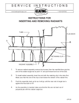
(see Fig. 3.1).
Fig. 3.1: Optimum heating distribution compared to representative temperature proles for radiant, baseboard and forced-air heating.
Ceiling
Eye Level
Optimum
Heating
Prole
Radiant
Floor
Heating
Baseboard
Radiators
Forced
Air
Heat
68°F (20°C)
68°F (20°C)
68°F (20°C)
68°F (20°C)
55°F (13°C)
70°F (21°C)
85°F (29°C)

6
3.3 Energy Efciency
Many new buildings are being designed to achieve certications, such
as LEED, Energy Star, or the NAHB National Green Building Program.
Legislation is requiring improved insulation of structures, inltration
testing and heat loss design methods. Radiant heating systems are
very capable of meeting these high standards. The energy efciency
of radiant walls, oors and ceilings comes from the following key
factors:
– Maintains thermal comfort in a room at a lower ambient room
temperature
– Delivers heat more efciently than other systems
– Loses no heat through ducts
– Results in less air inltration
The efciencies with radiant heating systems can translate into annual
energy savings for the building owner.
Note: Uncontrolled human factors, such as changing the design
temperatures, can dramatically affect efciency and energy usage of
any system.
3.4 Thermal Zoning
A thermal zone is an area of temperature control. Zoning the tempera-
ture in different areas of the building is generally required in commer-
cial, industrial and institutional installations, and may also be desirable
in residential installations.
Advantages of zoning include:
− Establishing different room temperatures based on comfort levels
− Reducing unoccupied room temperatures to save energy
− Reacting to heat input from occupants
− Reacting to heat input from solar gain
− Fine-tuning heat output into each room
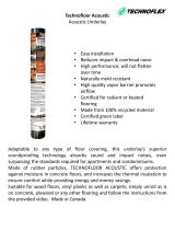
Wet Construction
Slab on grade Structural slab Overpour above
existing suboor
Dry Construction
Heat transfer panels Heat transfer panels
above suboor below oor in joist spaces
(dry panel) (dry plate)
Slab and Overpour
Wet construction of a radiant panel system embeds the pipe in a thick
concrete slab, or in a thin layer of gypsum, lightweight concrete or
mortar bed which is installed over a suboor.
Above-Floor Panels
A dry panel radiant heating system is installed directly on top of the
suboor without a concrete overpour. Pipes are installed in a grooved
conductive panel. Dry panel systems are considered low mass and
offer faster response times compared with wet systems.
Below-Floor Plates
In a dry plate radiant heating system, pipes are installed in the joist
spaces under a suspended wood oor. Heat transfer plates are used
to evenly distribute the heat, increasing the efciency of heat transfer
from the pipe to the bottom of the suboor.
3.5 Construction Methods
Radiant heating systems are installed in oors using wet or dry
construction methods. It is compatible with a variety of oor cover-
ings, including hardwood, carpet, vinyl, ceramic tile and natural stone.
Radiant heating may also be installed in walls and ceilings using the
dry panel construction.

7
REHAU offers pipes, ttings, manifolds, heat transfer panels and
plates, controls, and a variety of installation accessories and tools
for radiant heating systems. For a detailed description of our system
components, refer to REHAU Sustainable Building Technology Product
Catalog.
4.1 Pipes
RAUPEX
®
crosslinked polyethylene (PEXa) pipe is manufactured us-
ing REHAU’s high-pressure peroxide extrusion method that typically
yields the highest, most consistent level of crosslinking. Pioneered by
REHAU in 1968, PEXa technology enhances exibility and thermal
memory, providing ease of handling and kink repair while supporting
the use of REHAU compression-sleeve ttings.
RAUPEX has distinct advantages over metal and other polymer pipes:
– Resists pitting and stress corrosion
– Resists scaling and deposit build-up when used with both hard and
softened water
– Minimizes noise that is transmitted through pipes
– Withstands the high temperatures and pressures of hydronic heat-
ing systems
– Resists notching and abrasion damage
Fig. 4.1: RAUPEX pipe
4. SYSTEM COMPONENTS
RAUPEX is manufactured by REHAU in a facility whose quality
management system is ISO 9001 certied. Within the facility, REHAU
receives and mixes the raw materials, then extrudes and ships the
nished product. In addition, RAUPEX production is independently
monitored at least annually by Underwriters Laboratories Inc. (UL),
NSF International and CSA International.
4.1.1 Pipe Standards and Certications
RAUPEX pipes are designed for use in radiant heating systems.
They may also be used in other hydronic heating systems including
baseboard radiators, fan coils, convective n tube, panel radiators and
kick space heaters as long as the temperature and pressure ratings
are not exceeded.
For information on RAUPEX pipes meeting the requirements in the
United States and Canada, refer to REHAU PEX Piping Systems Certi-
catios and Listing.
RAUPEX pipes are accepted by the following model codes:
− IMC International Mechanical Code (IMC)
− International Building Code (IBC)
− International Residential Code (IRC)
− Uniform Building Code (UBC)
− Uniform Mechanical Code (UMC)
− National Building Code of Canada (NBC)
RAUPEX pipes can be used in radiant systems as described in:
− CSA B214, Installation Code for Hydronic Heating Systems
− Radiant Panel Association Guidelines for the Design and Installation
of Radiant Panel Heating and Snow/Ice Melt Systems
− ASHRAE 2008 Handbook HVAC Systems and Equipment, Chapter
6 Panel Heating and Cooling

8
RAUPEX Type Typical Application Characteristics Description
RAUPEX O
2
Barrier Radiant Heating - Has oxygen diffusion barrier Pipe provides superior
(EVOH) to limit oxygen permeation protection to ferrous components
- Color: bright red
RAUPEX UV Shield Potable Plumbing - Has colored HDPE outer layer to Pipe is protected (for a limited
improve protection against UV light time) from UV exposure during
- Does not have oxygen diffusion barrier construction before the wall
barrier coverings are installed
- Colors: matte red, blue, white
RAUPEX Non-Barrier Fire Protection - Does not have oxygen diffusion barrier Pipe markings are permanent
- Has limited UV protection which is a mandatory requirement
- Color: natural white
Table 4.1: Types of RAUPEX Pipes
4.1.2 Pipe Applications
REHAU provides three types of RAUPEX pipes for different ap-
plications; all three types have the same temperature and pressure
capabilities.
4.1.3 Pipe Dimensions
RAUPEX pipe is available in nominal sizes ranging from 3/8 to 2 in.
Pipe is in accordance to the dimensional standards dened in ASTM
F876. RAUPEX pipe is copper tube size (CTS) outside diameter (OD),
which means that the actual OD of the pipe is 1/8 in (3.18 mm) larger
than the nominal OD.
Wall thickness is dened by the standard dimensional ratio (SDR).
RAUPEX pipe is SDR 9, which equates to the outside diameter being
approximately nine times the wall thickness.
For pipe dimensions, pipe properties and other pipe technical informa-
tion, refer to the REHAU RAUPEX O
2
Barrier Product Submittal.

9
4.1.4 Pipe Performance Characteristics
Pressure and Temperature Ratings
The maximum temperature and pressure ratings of the RAUPEX pipe
are in accordance to ASTM F876, CSA B137.5 and PPI TR-3. The
designer shall determine the actual conditions and apply the appropri-
ate and additional design factors as required for any particular project.
According to the REHAU PEXa Limited Warranty, the RAUPEX pipe
warranty period is for operating conditions at or below 180°F (82.2°C)
in permitted applications when the handling, use, installation and
maintenance continually complies with all REHAU technical guidelines.
REHAU denes Elevated Temperature Applications as those with
operating conditions greater than 180°F (82.2°C). When REHAU PEXa
pipes are planned to be operated in Elevated Temperature Conditions,
contact REHAU Engineering to verify your project conditions comply
with the REHAU PEXa Limited Warranty in accordance to REHAU
Elevated Temperature Applications Technical Bulletin.
160 psi @ 73.4°F (1055 kPa @ 23°C)
100 psi @ 180°F (690 kPa @ 82.2°C)
80 psi @ 200°F (550 kPa @ 93.3°C)
Ultraviolet Resistance
Plastics are susceptible to damage from exposure to the ultraviolet
(UV) radiation in sunlight. PEX pipes can be designed to protect
against short-term UV damage, but after some time, UV radiation will
reduce the lifespan of the pipe. The extent of the reduction depends
on factors such as temperature, pressure and chlorination levels in
potable water. If excessive UV exposure occurs, a PEX pipe may not
last its full design life.
REHAU has performed extensive testing of RAUPEX pipes exposed
to natural sunlight, leading to the maximum UV exposure times
expressed in accumulated days shown in REHAU UV Resistance
Technical Bulletin. Once the pipes leave the manufacturing plant, any
exposure to UV, including transportation and storage by the whole-
saler, is part of the accumulated exposure time.
RAUPEX pipes must not be stored outdoors and are not designed for
permanent outdoor exposure (with the exception of buried applications).
NOTICE: Failure to follow maximum UV exposure limits may damage
the pipe resulting in leaks and operational failures, and will negate any
warranty provided by REHAU for RAUPEX pipes.
Oxygen Diffusion Properties
In typical radiant heating systems, hundreds or thousands of feet
of RAUPEX pipe will be used, providing a large surface area for
potential permeation of oxygen. The uncontrolled diffusion of oxygen
into closed radiant heating systems is an important issue for system
designers. The oxygen diffusion barrier on RAUPEX O
2
Barrier pipe
limits oxygen permeability as dened within DIN 4726, the accepted
German standard for limiting oxygen diffusion. Without an oxygen dif-
fusion barrier, oxygen (O
2
) can pass through the pipe wall, dissolve in
the heating water and corrode any ferrous components such as pipes,
valves, pumps and boilers. Concrete does not protect the system
because it is porous and oxygen can easily pass through it.
NOTICE: Use only O
2
Barrier pipe in heating systems with ferrous
components. Excessive oxygen in system may damage ferrous com-
ponents resulting in leaks and operational failures.

10
Chemical Compatibility
RAUPEX pipe is compatible with ethylene and propylene glycol, and
common corrosion inhibitors used in hydronic piping systems. Chemi-
cals that may damage RAUPEX pipe include (but are not limited to):
− Adhesives
− Oil or petroleum-based products
− Paints
− Solvents
− Oxidizing agents (e.g., bleach)
− Disinfectants (e.g., separate dosing unit integrated into building
distribution system)
Many factors, such as exposure time, temperature, pressure and
other operating parameters, can inuence the performance of a pipe
that is exposed to a chemical. To determine the impact of a particular
chemical, short- and long-term pressure testing may be required. In
some cases, a pipe may be resistant to short-term exposure to the
chemical, but not resistant to continuous exposure. Each chemical
must be evaluated individually.
NOTICE: Check compatibility before allowing chemicals to come in
contact with the exterior or interior of RAUPEX pipe. Chemicals may
damage the pipe resulting in leaks and operational failures.
Excessive Temperature and Pressure Capability
Temperature and pressure (T&P) relief valves are safety mechanisms
in case the system overheats (mandatory in hot water distribution
systems). These valves act quickly to relieve excess temperature or
pressure if either one of these conditions is reached. In the event
of a water heating system failure or T&P relief valve failure, RAUPEX
pipe has been tested to accommodate short-term exposure condi-
tions of 210°F (99°C) at 150 psi (10 bar) for 48 hours. The actual test
to obtain this short-term excessive temperature pressure capability
requires that the pipe and ttings withstand these conditions for at
least 720 continuous hours (30 days). This properly ensures that all
safety factors are met.
NOTICE: Failure to follow pressure and temperature limits may dam-
age the pipe resulting in leaks and operational failures, and will negate
any warranty provided by REHAU for RAUPEX pipes. The designer
must incorporate proper controls into the system to ensure the pres-
sure and temperature capability of the pipe is not exceeded.
Friction Loss
The pressure loss in the pre-insulated PEXa system depends on the
ow rate, water temperatures and the properties of the uid. Use the
REHAU LoopCAD
®
Software which includes a built-in calculator to
determine pipe pressure losses for the given conditions. Or refer to
the REHAU PEXa Piping Systems Pressure Loss Tables for the ap-
plicable pressure loss table presented at typical ow rates and water
temperature for propylene glycol. The pressure loss in PEXa carrier
pipe is based on the application of the D’Arcy-Weisbach equation and
uid properties from ASHRAE Fundamentals.

11
Fire Resistance in Fire-Rated Assemblies
It is common to install radiant heating pipes through re-rated wall
and oor/ceiling assemblies. Building codes require this be done with-
out diminishing the overall re rating of the assembly. The re-resis-
tance of RAUPEX pipe has been tested to the following standards.
− ANSI/UL 263, Fire Tests of Building Construction and Materials
− CAN/ULC-S101, Standard Methods of Fire Endurance Tests of
Building Construction and Materials
For technical information on the design listings, refer to REHAU
Installation of RAUPEX Pipe in Fire Rated Assemblies Technical
Bulletins.
WARNING: When using RAUPEX pipe in re-rated assemblies,
the specifying engineer and designer must evaluate the design
listing to ensure that local code requirements are met. Fire or
smoke that is not contained may lead to death or serious injury.
The Authority Having Jurisdiction should review and approve the
design before installation.
Building codes require installation of an approved through-penetration
restop system where pipes penetrate through a re-rated assembly
(i.e., oor, ceiling or wall). Some restop products are listed for all
assembly types, while others are listed for only specic assembly
types. RAUPEX pipe is re-stopped at both points of entry through the
re-rated assembly.
The restop system must be tested in accordance with one or all
of the following standards and listed by an independent third-party
listing agency such as UL, ULC or ITS (Warnock-Hersey). The restop
system must meet all local code requirements prior to installation. The
most common restop system standards are:
− ASTM E-814, Fire Tests of Through-Penetration Firestops
− UL 1479, Fire Tests of Through-Penetration Firestops
− CAN/ULC S115-M, Tests of Fire Resistance of Building
Joint Systems
When choosing an approved restop system for each specic installa-
tion, the following information must be known:
− Nominal size of PEX pipe penetrating the re-rated assembly
− Number of PEX pipes penetrating through one opening
− Construction of re-rated assembly (e.g., wood or concrete)
− The "F" and "T" ratings of the re-rated assembly
− Type of assembly being penetrated (e.g., oor, ceiling or wall)
NOTICE: The designer must ensure the restop materials are compat-
ible with the RAUPEX pipe. Chemicals may damage the pipe resulting
in leaks and operational failures.
Flame and Smoke Spread Ratings
A plenum is an enclosed portion of a building structure that is
designed to allow air movement, thereby serving as part of an air
distribution system. Plenums can serve as supply, return, exhaust and
ventilation portions of the air distribution system.
Typically, building codes require that combustible materials installed
within air plenums have a ame spread rating of not more than 25,
and a smoke developed rating of not more than 50. These ratings are
assigned during standardized laboratory tests that burn the combus-
tible pipe and measure the speed of ame spread and the volume of
smoke developed. Pipes that meet these requirements are sometimes
said to have a “plenum rating.”
United States and Canada have different, but similar, standards for
this test. These standards are:
− ASTM E84, Surface Burning Characteristics of Building Materials
− CAN/ULC S102.2, Standard for Surface Burning Characteristics of
Flooring, Floor Covering and Miscellaneous Materials and
Assemblies
RAUPEX Non-Barrier, UV Shield and O
2
Barrier pipes (1/2 to 2 in.
sizes) have been tested to both the US and Canadian standards.
Based on this testing, some sizes and types of RAUPEX require an
outer jacket of berglass insulation that is listed to the E-84 and
S102.2 standards.
For technical information on the plenum rating of RAUPEX pipes,
refer to REHAU Installation of RAUPEX Pipe in Air Distribution Plenums
Technical Bulletins.

12
Freeze Break Resistance
The exibility of the RAUPEX pipe allows it to expand as water freezes
in the pipe as long as the pipe has room to expand. When the water
thaws, the pipe returns to its original shape. If the pipe is not allowed
to expand (e.g., it is encased in concrete), it may burst.
NOTICE: Designers must take precautions to ensure that pipes do
not freeze. Frozen pipes may burst resulting in leaks and operational
failures.
Chlorine Resistance
RAUPEX pipe has been tested by NSF International in accordance
with ASTM F2023, Standard Test Method for Evaluating the Oxidative
Resistance of Cross-linked Polyethylene (PEX) Tubing and Systems
to Hot Chlorinated Water as required in ASTM F876. RAUPEX pipe
exceeds the minimum extrapolated test lifetime as certied by NSF
and PPI for cold water applications, intermittent hot water applications
and timed hot water applications.
Linear Expansion and Contraction of RAUPEX Pipe
Embedding RAUPEX pipe in concrete or securing it in RAUPANEL or
RAUPLATE restricts its ability to expand and contract. Unrestrained
pipe will expand and contract when heated and cooled. To accom-
modate the operating expansion and contraction of RAUPEX pipe, a
deection leg may need to be incorporated into the pipe layout.
The amount of expansion or contraction in a length of RAUPEX pipe is
calculated using the equation:
ΔL = L × ΔT × α
where
ΔL change in length
L original length
ΔT change in temperature
α coefcient of expansion.
In general, RAUPEX pipe expands approximately 1 inch per 100 ft for
every 10°F rise in temperature (or approximately 10 mm per 10 m for
every 6°C).
4.1.5 Pipe Markings
Pipe markings are repeated every 3 ft (0.9 m), list all certications
and approvals, and include an incremental footage marking to assist
with installing the pipe. RAUPEX pipe is further identied with a PEX
Material Designation code in accordance to ASTM F876.
4.1.6 Pipe Compatibility With PEX Fitting Systems
RAUPEX pipe is marked with the ASTM standard specication num-
bers of compatible PEX tting systems.
4.1.7 Pipe Material Safety Data Sheet (MSDS)
The Occupational Safety and Health Administration (OSHA) Hazard
Communication Standard requires suppliers and manufacturers to is-
sue an MSDS for chemicals dened as "hazardous" by OSHA. Under
normal conditions of use, RAUPEX pipe does not expose employees
to potentially harmful chemicals. RAUPEX pipe meets the denition of
articles in OSHA 29 CFR 1910.1200 and is exempt from the require-
ment to provide an MSDS.

13
4.1.8 Pipe Packaging, Handling and Storage
RAUPEX pipe coils are shipped in cardboard boxes to protect them
from sunlight, rain, dirt and other hazards. Straight lengths of RAUPEX
pipe are packaged and shipped in durable black polyethylene bags.
Keep pipe in the original packaging until it is required for installation.
Return unused pipe to the packaging.
RAUPEX must be handled with care. Avoid the following:
– Dragging it over rough objects such as gravel or concrete
– Contact with oil or oily products such as gasoline and paint thinner
– Exposure to soldering or any open ame
– Excessive or permanent exposure to sunlight
4.1.9 Pipe Bending
RAUPEX pipe sizes up to 1 1/4 in. may be bent, even when cold.
REHAU Support Bends make it fast and easy to create tight bends
without kinking. The typical bend radius used by the installer is 8X
the OD. The minimum bend radius is 5X the OD for cold bends. For
an even smaller bend radius, the pipe may be heated with a hot air
gun and bent to no less than 3X the OD. If a tighter bend radius is
required, then the designer should consider using a smaller diameter
pipe. Pipe bends are classied according to the centerline radius
(CLR) of the bend as a ratio to the outer pipe diameter.
Note: A pipe may become kinked from excessive bending which may
obstruct or reduce the ow. Kinked pipes may be repaired with a hot
air gun.
Fig. 4.3: Centerline radius (CLR) of RAUPEX pipe
Bend Radius Typical Min. Cold Min. Heated
8X OD 5X OD 3X OD
Pipe Size in (mm) in (mm) in (mm)
3/8 in 4.0 (102) 2.500 (64) 1.500 (38)
1/2 in 5.0 (127) 3.125 (79) 1.875 (48)
5/8 in 6.0 (152) 3.750 (95) 2.250 (57)
3/4 in 7.0 (178) 4.375 (111) 2.625 (67)
1 in 9.0 (229) 5.625 (143) 3.375 (86)
1 1/4 in 11.0 (279) 6.875 (175) 4.125 (105)
For RAUPEX pipe sizes 1 1/2 in. and greater, use elbow and other ttings to
accomplish tight bends.
4.1.10 Pipe Repair of Kinks
RAUPEX pipe is exible and resists kinking even at temperatures well
below freezing. Should the pipe become accidentally kinked, it is pos-
sible to restore the pipe to its original shape by removing any stress
from the pipe and gently heating the pipe, taking care not to overheat
and damage the surface of the pipe. Due to the memory effect, the
pipe will return to its original shape.
Refer to the REHAU Radiant Heating Installation Guide for instructions
on performing kink repairs.
4.1.11 Pipe Protection
Place pipe protection around RAUPEX pipe to prevent abrasion when
passing through holes in the building's framework. Protection is not
required for installation in wood studs, walls, oor plates or joists if
the following provisions are met:
− The hole is at least 1/4 in (6 mm) larger than the outside diameter
(OD) of the pipe
− The pipe is free to move for expansion and contraction
− The hole is clean (e.g., free of splinters, burrs, and rough edges)
− The hole has smooth, non-abrasive interior surface (e.g., bushing)
Note: To minimize noise associated with joist space installations,
REHAU highly recommends use of pipe protection at all joist penetra-
tions.
At concrete slab penetrations, RAUPEX pipes should be protected.
Where RAUPEX pipe passes through holes in concrete, masonry or
steel, pipe protection is always required.
Table 4.2: Bend Radius of RAUPEX Pipe
90°
CLR
O.D.

14
4.2 Fittings - Compression-sleeve
The REHAU compression-sleeve tting system employs the memory
inherent in RAUPEX pipe to form a secure joint. The RAUPEX pipe is
expanded to allow the tting to be inserted. Because of its crosslinked
structure, the pipe tries to return to its original shape, placing signi-
cant force on the tting and forming a tight joint.
REHAU compression-sleeve ttings are designed for use exclusively
with REHAU pipe and must be assembled only with REHAU com-
pression-sleeve tools. The systems offer a variety of congurations to
meet different radiant piping system applications.
A properly assembled compression-sleeve joint can be placed in areas
that will become inaccessible after installation, such as behind sheet-
rock or under a oor or slab. Always check with local codes to verify
which types of joints, if any, may be used in inaccessible locations.
REHAU compression-sleeve ttings meet the requirements of
ASTM F877 and CSA B137.5.
Refer to the REHAU F2080 Compression Sleeve Product Instructions
for the pressure losses, installation considerations and assembly of
F2080 compression-sleeve ttings.
Refer to the REHAU EVERLOC+ Assembly Product Instructions for
the pressure losses, installation considerations and assembly of
EVERLOC+ ttings.
4.3 Fittings - Compression Nut
The REHAU compression nut tting is used where pipe remains ac-
cessible after installation. It allows easy disassembly of the pipe from
the connected device such as a manifold, another tting or a piece of
equipment. The tting can be assembled with a pipe wrench and does
not require special REHAU tooling. REHAU compression nut ttings
meet the requirements of ASTM F877 and CSA B137.5.
The basic process of completing a compression nut joint is to:
− Install compression union nut, then split clamping ring over end of pipe
− Insert tting into end of pipe
− Tighten nut onto tting
R20 Fittings are removable, threaded connections that transition the
RAUPEX heating circuit pipe into the PRO-BALANCE or HLV manifold.
Copper Adapters Fittings transition the RAUPEX distribution pipe to
copper pipe.

15
4.4 Manifolds
Manifolds distribute and control the heating water to the different
circuits in a radiant heating system. Manifolds may be mounted in any
orientation (e.g., inverted, horizontal or sideways).
PRO-BALANCE Manifolds have separate supply and return headers.
Circuit connections branch off from the headers and balancing valves
control the ow rate to each circuit connection. A valve actuator
may be installed to the header balancing valve to open and close the
circuit.
HLV Manifolds have separate supply and return headers. These
"valve-less" manifolds have circuit connections that connect directly
to the pipe. Manifolds may be used when circuit lengths are within
10% and ow rate requirements are the same for all circuits.
Flow Gauges
Distribution Number Maximum with Manual Automatic
Supply and of Flow Circuit Balancing Control Circuit
Return Sizes Circuits (GPM) Isolation Adjustment Valves Connections
PRO-BALANCE 1 in NPT 2 to 12 20 √ √ √* R20
1 1/4 in NPT 2 to 10 40 √ √* R20
HLV 1 in NPT 2 to 5 20 √ R20
Ball Valve 1 in Cu pipe 12 20 √ Compression-sleeve
1 1/4 in Cu pipe 12 32 √ Compression-sleeve
Cut-to-Length 1 in Cu pipe 12 or 24 20 Compression-sleeve
1 1/4 in Cu pipe 12 or 24 32 Compression-sleeve
Pre-cut 1 in Cu pipe 2 to 4 20 Cu pipe
Header Stock 1 in Cu pipe 24 20 Cu pipe
1 1/4 in Cu pipe 24 32 Cu pipe
1 1/2 in Cu pipe 24 44 Cu pipe
2 in Cu pipe 18 or 24 75 Cu pipe
Table 4.3: Manifold Comparison
Ball Valve and Cut-to-Length Manifolds have a single header and
the pipe circuit connections are accomplished with the permanent
EVERLOC tting.
Pre-cut and Header Stock Manifolds have a single header and
smaller copper tube outlet tees for connecting to the radiant heating
circuit.
Manifold Cabinets are used with the PRO-BALANCE and HLV mani-
folds in commercial, industrial and institutional applications.
Notes: Cu = copper (*) compatible but not included

16
4.5 Heat Transfer Panels
Heat transfer panels overlay the suboor and contain channels which
accept the RAUPEX pipe. REHAU's patented RAUPANEL Radiant
Heating System consists of RAUPEX pipes, aluminum panels, plywood
return bends and plywood furring strips. These components are
designed for ease of installation as well as excellent thermal perfor-
mance. The system allows for either 6 or 8 in (15 or 20 cm) on-center pipe
spacing, as required to meet radiant panel performance requirements.
RAUPANEL is an extruded aluminum panel which has a custom
Omega-shaped groove that allows pipe to be tightly snapped into
place, maintaining excellent thermal contact between the pipe and
panel. The pipe installation does not require silicone or other ller
materials. The unique prole of the highly-conductive aluminum
panel makes it responsive, strong and lightweight. Five integral legs
on the bottom support the panels, the weight of the ooring and the
loads above, while reducing the thermal contact with the suboor
below. This reduced contact increases the directional efciency of the
panels, since the majority of the heat drawn from the RAUPEX pipe is
conducted across the top surface of the panel and to the oor, wall or
ceiling panel. This often means that no insulation is required in a joist
cavity below the panel system, saving installation time and material
costs.
Plywood Return Bends are congured to maintain the pipe spacing
during installation. The 6 in (15 cm) on-center return bends allow for
aluminum panels to be installed side-by-side, providing maximum alu-
minum coverage in areas where even more heat delivery is required.
The 8 in (20 cm) on-center return bends are specially notched to align
the aluminum panels and the pipe groove, simplifying system instal-
lation. Return bends are machined from construction-grade plywood
to match the height of the aluminum panels, and are pre-grooved for
easy pipe installation.
Plywood Furring Strips provide nailing surfaces for certain types
of ooring. These precision-cut furring strips are used primarily with
8 in (15 cm) return bends to ll the gaps between the aluminum
panels. They are also used at the edges of panel layouts to provide
nailing surfaces and to keep a space between the aluminum panels
and outside wall plates and studs, reducing heat loss through exterior
walls. Furring strips are machined from construction-grade plywood to
match the height of the aluminum panels.
4.6 Heat Transfer Plates
Heat transfer plates are installed below the suboor in the joist cavity
and contain channels which accept the RAUPEX pipe. Installations are
typically 8 in (20 cm) on-center with two pipes running the length of
each joist cavity.
RAUPLATE
™
Heat Transfer Plates are xed to the underside of
a suspended joist space oor. Each plate has two channels spaced 8
in (20 cm) on-center. The RAUPEX pipes clip quickly and rmly into
the channels. RAUPLATE typically offers faster and easier installation
than other heat transfer plates.
Heavy Gauge Heat Transfer Plates are xed to the underside of a
suspended joist space oor. The single-channel plates are used when
there is only one run of pipe in the joist cavity or to position the pipe
around obstructions where the two-channel plates do not t. The
RAUPEX pipes clip rmly into the channel.

17
Insulation Screw Clips secure the pipe directly to rigid board insula-
tion which is an aid when laying pipe, and prevents the pipe from
oating up to the surface with wet construction methods. The polymer
screw clips insert easily into the insulation with the aid of the screw
clip tool provided separately.
Plastic Holding Pins secure the pipe directly to rigid insulation which
is an aid when laying pipe, and prevents the pipe from oating up to
the surface with wet construction methods.
Soil Hooks anchor pipe in compacted soil.
4.7.4 Pipe Rails
RAILFIX
™
Rails allow for rapid installation by securing the pipe prior
to pouring the slab or overpour in a wet construction method. The
rigid polymer channel has xed pipe slots spaced every 2 in (5 cm).
Universal Fixing Rails allow for the same rapid installation as the
RAILFIX with the added benet that four different pipe sizes, ranging
from 3/8 to 3/4 in., may be secured. The rigid polymer molding has
alternating small and large pipe tabs spaced every 4 in (10 cm).
Fixing rails may be mounted onto insulation with Plastic Holding Pins
or onto concrete and wood oors with screws.
Table 4.4: Accessory Comparison
Construction Distribution
Methods Piping and
Wet Dry Circuit Tails
Support Bends √
Bend Guides √
Protection Sleeves √ √
RAUCROSS Sleeving √
Locking Clips √
Pipe Talons √ √
Single Nail Clamps √
Plastic Pipe Clamps √
Isolating Suspension √
Clamps
Nylon Pipe Ties √
Insulation Screw Clips √
Plastic Holding Pin √
Soil Hooks √ √
RAILFIX Rails √ √ √
Universal Fixing Rails √ √ √
4.7 Installation Accessories
Accessories are used in a variety of radiant heating construction
methods.
4.7.1 Pipe Assembly Guides
Steel and Polymer Support Bends assists the installer in creating
90° bends of the distribution piping and circuit tails without kinking
the pipe. The support bends snap over the pipe.
4.7.2 Pipe and Fitting Protection
PVC Bend Guides provide protection at slab penetrations and create
a professional appearance. Pipe is inserted into the 90° rigid PVC
guides, then half of each guide is embedded in the slab.
PE Protection Sleeves protect the pipe at slab, wall and joist pen-
etrations, expansion and construction joints, and abrasive surfaces.
The protection sleeves reduce abrasion and minimize noise caused by
the expansion and contraction of the pipe.
RAUCROSS
™
Sleeving is ideal for sealing around ttings installed in
corrosive environments or buried in a slab. The heat shrink sleeving
tightly seals around the tting with heat from a hot air gun.
4.7.3 Pipe Hangers
Locking Clips allow for rapid installation of pipe. The pipe snaps into
the clips and can be removed without damaging the clips. The poly-
mer clips attach to the surface with a screw or nail (not included).
Pipe Talons clip onto the pipe.
Single Nail Clamps completely encircle the pipe. Both the polymer
talon and polymer clamp secure the pipe to the wood framework with
a pre-installed barbed nail.
Isolating Suspension Clamps secure suspended pipe to both wood
and metal framework.
Plastic Pipe Clamps secure pipe to both wood and metal framework.
Nylon Pipe Ties safely secure pipe directly to slab reinforcing bars or
wire mesh. This installation method is most common in commercial
applications.

18
5. SYSTEM PLANNING
Planning and designing a radiant heating system involves many objec-
tives: economy, comfort, zoning and use of space. This chapter identi-
es the information the designer needs to gather and understand
before beginning the system design of a specic installation.
REHAU provides a general construction specication that can be in-
cluded in the project's master plan. The specication is intended to be
edited by the designer to meet the needs of the project. The REHAU
Radiant Heating Specication may be obtained from the REHAU
Resource Center.
5.1 Building Layout
To do an accurate and complete job, the radiant designer needs
a current set of drawings and specications for the building. The
designer also needs a clear understanding of any additional heating
and ventilation systems to be used, and the ability to discuss certain
design issues with the owner and/or the owner’s agent.
The building’s structure and the oor nish installation inuences the
decision regarding the best radiant heating construction method. Floor
construction methods play an important role in the performance of the
radiant heating system. The oor should allow for the heat from the
pipes to dissipate readily and evenly to the heated space. Downward
heat ow should be minimized by employing adequate insulation. Cer-
tain radiant construction methods involve penetrations through oor
joists or other details which may be governed by local codes. Check
with applicable code authorities to determine specic requirements.
Walls and ceilings may be used in retrot projects to increase the
radiant heat output of rooms with oor areas too small to provide
sufcient heat.
5.2 Building Heat Loss
The designer needs to calculate the building heat loss before design-
ing a radiant heating system. A heat loss calculation is performed,
based on the outdoor design temperatures, and taking into account
conductive heat loss through all exterior building panels (e.g., walls,
ceilings, oors, windows and doors) and air changes related to air in-
ltration and mechanical ventilation. In some cases, heat loss through
interior building panels is also calculated, such as where temperature
differences exist between adjacent rooms. When designing a building
with radiant heating, special attention must be paid to the radiant
panels themselves, as the heat lost through a heated oor may be
higher than the heat lost through an unheated oor.
Calculations for heat loads are typically based on outside design tem-
peratures for the project location, and do not assume other sources of
heat gain, such as solar gain, heat from occupants, machinery, com-
puters or lights. This results in a heating system that is sized correctly
for worst-case conditions with no articial sources of heat gain.
Several heat loss calculation methods are used throughout North
America. Different heat load calculation techniques apply to residen-
tial, commercial, industrial and institutional facilities. Certain building
codes require the use of specic heat loss programs. Determine the
applicable laws by checking with the local municipality and/or building
inspection department. To design a radiant heating system, the heat
loss calculations should be performed according to one of the follow-
ing standards or equivalent:
− ASHRAE
− ACCA - Manual J (residential)
− ACCA - Manual N (commercial)
Detailed heat loss calculations must be done as accurately as possible
to accurately size all system components—the heat source, distribu-
tion pipes, manifolds, valves, circulator pumps, expansion tanks and
other hydronic components. Under sizing components can result in
a heating system that does not meet the demand at peak load. Over
sizing components can result in short-cycling of boilers or circulator
pumps, noise and vibration, poor control over heating water or room
temperatures, inadequate comfort and loss of efciency. In some
cases, components can fail if not sized correctly.
5.3 Room and Building Temperatures
In the planning stage, the designer should consider the thermal
comfort of the occupants. Be sure to consult with the building owner
regarding the desired target temperature setpoint. The thermal
comfort for a person in a room is determined by the activity of the
person, clothing worn by the person, ambient room temperature, air
speed, humidity and surface temperatures in the room (e.g., walls,
oors, ceilings and furniture). Radiant heating systems warm surfaces,
objects and air in the lower portions of the space, allowing thermo-
stats to be lowered 2 to 4°F (1 to 2°C) compared to conventional
forced-air heating systems without sacricing the occupants thermal
comfort level.

19
Typical Room Ambient Air Temperatures
Typical target ambient room temperatures used for a radiant heating
design are:
− 60-65°F (16-18°C) for most warehouses
− 65-68°F (18-20°C) for most occupied spaces
− 70-74°F (21-23°C) for most bathrooms
Maximum Radiant Panel Surface Temperatures
Radiant oors are an excellent heating source.
Floor temperature limitations exist to ensure occupants feet are
not overheated, while still providing enough heat to meet the room
requirement.
Human Comfort Exposure Limits Temperature °F (°C)
Floors in occupied areas 85 (29)
Floors in perimeter areas 95 (35)
Floors in bathrooms 91 (33)
Floors in distribution areas 95 (35)
such as hallways and secondary rooms
Table 5.1: Typical Maximum Floor Surface Temperatures
Walls and ceilings are allowed to have higher temperatures because
of their limited contact with occupants. Wall temperatures may be
as high as 95°F (35°C). Ceiling temperatures may be even higher,
depending on the ceiling height.
NOTICE: Excessive temperatures can overheat and damage oor, wall
and ceiling structures or coverings causing discoloration, warping or
cracking. Ensure that your radiant designs conform to the maximum
allowable temperature dened by the manufacturer of these materials.
5.4 Building Zoning
With radiant heating, thermal zoning is accomplished by controlling
the ow of water through individual pipe circuits or manifolds. Zones
can be as small as a bathroom or bedroom, or as large as an entire
Zoning is accomplished by controlling the ow of water through indi-
vidual pipe circuits or manifolds. A zone may have just one circuit of
radiant heat or may have many circuits that operate together. A zone
may have just one circuit of radiant heat or may have many circuits
that operate together.
Building Use
Zoning the radiant heating system considers the use of the building
in addition to the target ambient temperature requirements of the
occupants.
Residential: Residents will typically use different rooms, such as
bedrooms versus kitchens, at different times of the day. Rooms that
are used together should be zoned together. Rooms that are not used
for substantial periods of time, such as formal dining areas, should
be zoned separately, so that thermostats can be set back to conserve
energy and reduce operating costs.
Commercial: Commercial buildings usually include one or two types
of activities, such as eating or shopping, and may change over the life
of the building. Zoning should be versatile enough to accommodate
changes in use patterns.
Industrial: The industrial process usually determines the zoning, and
may also involve large pieces of machinery which may add to the heat
in the room.
5.5 Insulation
Insulation systems are very important for achieving the designed
radiant heating panel performance. Downward and edge heat losses
from radiant panels may be signicant, up to 50%, if the proper
insulation methods are not installed. With recommended insulation
levels, the downward heat loss can be as low as 10% of the total heat
load. Insulation behind radiant panels is critically important to direct
the ow of heat correctly, to improve response time and to maximize
energy efciency. In between oors, insulation helps to improve the
system performance and room temperature control. Many types of
insulation may be used, depending on the application and local codes.
Note: Check your state, provincial or local codes to ensure your design
complies with minimum insulation requirements, if they exist
.
5.6 Floor Coverings
Floor products used with radiant heating systems should have high
heat transmission values (low R-values) to achieve the best possible
heat transfer from the pipes to the room. Floor coverings should
also be as thin and dense as possible and be able to withstand the
heat output of the radiant panel. Every oor covering has a specic
temperature limit. Some typical examples of ooring R-values and
suggested maximum allowable temperatures are shown in Table 5.2.
Wood oors are the most sensitive to heat output from radiant panels.
NOTICE: Flooring products can be damaged by improperly designed
radiant systems leading to discoloration, noise, delamination, warping,
cracking and deterioration of the ooring products.
– Verify oor products are approved for use with radiant heating
systems
– Check oor temperatures are within the limitations set by the
manufacturer of the oor coverings, underlayments, adhesives
and grouts

20
Maximum Suboor Thickness Resistance R-value
Surface Temp* in h•ft
2
•ºF/BTU
Finished Floor Surface °F (°C) (mm) (m
2
•K/W)
Bare oor N/A N/A 0
Solid hardwood 85° 3/4 in 0.68
(27°) (19 mm) (.12)
Laminated hardwood 90° 11/16 in 0.87
with adhesive (32°) (17 mm) (.15)
PVC/linoleum with adhesive 100° 3/16 in 0.26
(38°) (4 mm) (.05)
Ceramic tile oor with mortar bed 100° 1/4 in 0.23
(elastometric bonding agent) (38°) (6 mm) (.04)
Natural stone with mortar bed 100° 1 1/2 in 0.21
(38°) (38 mm) (.03)
Carpet (polyester) 88° 3/8 in 1.17
with rubber pad (31°) (9 mm) (.21)
Solid Hardwood
Radiant heating can be installed with solid hardwood ooring with very
good results as long as the radiant panel design adheres to moisture
limits, oor temperature limits and installation considerations. Many
species of solid hardwood ooring can withstand the radiant panel
surface temperatures. Information on a specic species of hardwood
may be obtained from the manufacturer as well as from the Radiant
Panel Association (www.radiantpanelassociation.org), the National
Wood Flooring Association (http://www.nwfa.org) and The Hardwood
Council (www.hardwoodcouncil.com).
Engineered Hardwood or Laminate Hardwood
Engineered hardwood and laminate hardwood oors are an excellent
choice for use with radiant heated oors. With higher density and
lower thickness, these ooring solutions are often more conductive
(lower R-value) than solid hardwood ooring. This ooring is usually
compatible with radiant panel surface temperatures, and because it
absorbs less moisture than solid hardwoods, it is more suitable for
wet construction methods.
Engineered hardwood ooring has a thin top layer of solid hardwood,
typically 1/16 to 1/8 in (2 to 3 mm) thick, bonded to plywood under-
neath. With a solid hardwood surface, engineered hardwood oors are
available in many species and colors yet offer the structural stability of
plywood.
Laminate ooring is usually melamine-infused paper bonded to a
berboard core. Laminate oors are available in patterns and colors,
and offer the structural stability of the berboard material. Additional
information may be obtained from the Laminate Flooring Site (www.
thelaminateooringsite.com) or Laminate Floorings (www.Laminate-
Floorings.net).
Vinyl and Linoleum
Vinyl tiles are highly affected by oor temperatures. Consult with
the manufacturer to determine the maximum radiant panel surface
temperature allowable for the adhesive and the covering.
Ceramic Tile, Natural Stone or Bare Concrete
Ceramic tile, pavers, marble, stamped or stained bare concrete, and
other stone nishes are ideal for radiant surfaces. An underlayment
(e.g., backerboard or isolation membrane) is installed between the ra-
diant panel and the tile/stone to reduce movement and isolate cracks.
Tile cement with high heat capability should be used.
Carpeting and Padding
Carpeting and padding may be used over a radiant heated oor if
properly selected. Carpet and carpet pads with relatively high R-
values, such as urethane carpet and pads, will signicantly reduce
the radiant heating performance, and are not recommended. Typical
carpet pads suitable for radiant oors are made from thin slab rub-
ber, synthetic ber, or styrene butadiene rubber (SBR). Consult with
the manufacturer to determine the maximum radiant panel surface
temperature allowable for the carpet, pad and adhesives, if used. Ad-
ditional information may be obtained from the Carpet and Rug Institute
(www.carpet-rug.org).
Table 5.2: Maximum Temperatures and R-values for Typical Floor Coverings
*Note: Typical values presented; the designer must verify actual limits of the selected nish ooring materials with the manufacturer
/