Page is loading ...

Owner’s Manual
Read and save these
instructions.
For help please visit
honeywellhome.com
Line Voltage
Electric
Baseboard Heat
Thermostat CT60A,B
Application
Your new CT60 Series Electric Heating Thermostats provide line voltage control
of electric baseboard healing systems within the ratings listed on the front of
this instruction sheet. CT6OA replaces 2 wire thermostat; CT60B replaces 4 wire
thermostat. Wire connectors are not supplied. Use certified wire connectors approved
for No. 12 wires.
WARNING Electrical Shock Hazard.
This thermostat is a line voltage control (120240 Volts). Do not install it if you
are not completely familiar with house wiring. If handled improperly, there is
risk of electric shock hazard, which may cause serious injury or death.
Specifications
• CT60A single-line break 2 wires
• CT60B double-line break in OFF position4 wires
Temperature Range: 10° C to 30°C temperature range
Electrical Ratings: 60 Hz noninductive; 22A at 120240 Vac; 19A at 277 Vac

2
ATTENTION: MERCURY RECYCLING NOTICE
This product does not contain mercury.
However, this product may replace a product
that contains mercury. Mercury and products
containing mercury should not be discarded in
household trash.
For more information on how and where to
properly recycle a thermostat containing
mercury in the United States, please refer to the
Thermostat Recycling Corporation at
www.thermostat-recycle.org.
For mercury thermostat recycling in Canada,
please refer to Switch the Stat at
www.switchthestat.ca
NO MERCURY
Hg
Preparation for Installation
1. Before proceeding, first turn off power to the healing system at the main
fuse or circuit breaker panel. See warning note.
2. When replacing your old thermostat, remove the two mounting screws of
your old thermostat and pull out of the junction box.
3. Label the wires in the junction box, so that they match the thermostat
wires to which they are attached.
4. Disconnect the old thermostat.
Wiring and Installation
1. When installing your new thermostat, remove the prestripped insulation
tips from your new thermostat´s leads.
2. Re-connect wires in the junction box to matching leadwires on back of
the thennostat. See wiring diagram below. NOTE: Do not connect power
supply LIL2 to L1TI, to avoid thermostat burn - out.
CAUTION
Use certified soIderless wire connectors (not included) approved for
No. 12 wires and tighten them firmly so they cannot be pulled off.
Failure to tighten firmly may cause overheated connection.
3. Remove thermostat cover.
4. Mount the thermostat to the junction box using two capitive screws
provided. Do not press the knob or bimetal sensing element during
mounting.
5. Replace the thermostat cover.

3
Wiring
L1
(HOT)
L2
L1
T1
CT60A
SOLDERLESS
CONNECTORS ELECTRIC
HEATER
M35684
1
2
3
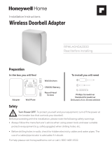
Fig. 1 CT60A wiring diagram.
1. Power supply provide disconnect means and overload protection as
required.
2. Special service co/air solderless connectors must be used when
connecting with aluminum conductors. Otherwise a fire hazard may result.
3. L1T1 closes on temperature fall.
M35685
L1
(HOT)
L2
ELECTRIC
HEATER
SOLDERLESS
CONNECTORS
RED
WIRE
CT60B
L1
L2
T1
T2
12
3
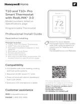
Fig. 2 CT60B wiring diagram.
1. Power supply provide disconnect means and overload protection as
required.
2. Special service co/air solderless connectors must be used when
connecting with aluminum conductors. Otherwise a fire hazard may result.
3. L1T1 closes on temperature fall.
L2T2 opens only in off position.

4
Check Out Thermostat
1. Turn temperature setting dial fully counter clockwise .
2. Turn the power back on.
3. Turn the temperature setting dial fully clockwise listen for the “click”
sound as switch makes contact. Electric heater should warm up within
2 - 10 minutes.
4. Turn temperature setting dial fully counter clockwise listen for the
“click” sound as switch breaks contact Electric heater should shut off and
cool down.
5. Set the dial to normal comfort temperature.
Troubleshooting
Your thermostat requires little or no attention. Most problems can generally
be traced to the following:
Symptom Checkout Action
No heat. Blown fuse or tripped circuit
breaker.
Replace fuse or reset breaker
Improper connections to
thermostat.
With power to circuit OFF, tighten all
wiring connections. Repair any frayed or
broken wires.
Other. Contact a qualified electrician for
assistance.
Heater never turns off. Turn temperature setting dial
fully counterclockwise .
1. Electric heater should start to cool
within 210 minutes.
2. If heater does n start to cool then
turn off power at the main service
panel and reconfirm that wiring is in
accordance with wiring diagram.
Other Contact a qualified service technician
for assistance

5
1-year limited warranty
Resideo warrants this product, excluding battery, to be free from defects in workmanship or materials, under normal
use and service, for a period of one (1) year from the date of first purchase by the original purchaser. If at any time
during the warranty period the product is determined to be defective due to workmanship or materials, Resideo shall
repair or replace it (at Resideo’s option).
If the product is defective,
(i) return it, with a bill of sale or other dated proof of purchase, to the place from which you purchased it; or
(ii) call Resideo Customer Care at 18004681502. Customer Care will make the determination whether the product
should be returned to the following address: Resideo Return Goods, 1985 Douglas Dr. N., Golden Valley, MN 55422,
or whether a replacement product can be sent to you.
This warranty does not cover removal or reinstallation costs. This warranty shall not apply if it is shown by Resideo
that the defect was caused by damage which occurred while the product was in the possession of a consumer.
Resideo’s sole responsibility shall be to repair or replace the product within the terms stated above. RESIDEO SHALL
NOT BE LIABLE FOR ANY LOSS OR DAMAGE OF ANY KIND, INCLUDING ANY INCIDENTAL OR CONSEQUENTIAL
DAMAGES RESULTING, DIRECTLY OR INDIRECTLY, FROM ANY BREACH OF ANY WARRANTY, EXPRESS OR
IMPLIED, OR ANY OTHER FAILURE OF THIS PRODUCT.
Some states do not allow the exclusion or limitation of incidental or consequential damages, so this limitation may
not apply to you.
THIS WARRANTY IS THE ONLY EXPRESS WARRANTY RESIDEO MAKES ON THIS PRODUCT. THE DURATION OF ANY
IMPLIED WARRANTIES, INCLUDING THE WARRANTIES OF MERCHANTABILITY AND FITNESS FOR A PARTICULAR
PURPOSE, IS HEREBY LIMITED TO THE ONE YEAR DURATION OF THIS WARRANTY. Some states do not allow
limitations on how long an implied warranty lasts, so the above limitation may not apply to you.
This warranty gives you specific legal rights, and you may have other rights which vary from state to state. If you have
any questions concerning this warranty, please write Resideo Customer Care, 1985 Douglas Dr, Golden Valley, MN
55422 or call 18004681502.

33-00145EF-0
3
www.resideo.com
This product is manufactured by Resideo Technologies, Inc., Golden Valley, MN, 1-800-468-1502
© 2019 Resideo Technologies, Inc. The Honeywell Home trademark is used under license from Honeywell
International Inc.
All rights reserved.
Resideo Inc., 1985 Douglas Drive North
Golden Valley, MN 55422
33-00145EF—03 M.S. Rev. 06-19 | Printed in United States

CT60A,B
Veuillez lire le mode
d’emploi et le conserver en
lieu sûr.
Pour obtenir de l’aide veuillez
visiter honeywellhome.com
Manuel du
propriétaire
Thermostats
tension secteur
pour plinthes
chauffantes
électriques
Application
Votre nouveau thermostat CT60 pour chauffage électrique assure la régulation
tension secteur des plinthes chauffantes selon les caractéristiques nominales
ci-dessus. Le CT60A peut servir à rem placer un thermostat bifilaire; le CT60B peut
servir à remplacer un thermostat à 4 fils. Les connecteurs ne sont pas fournis. Utiliser
des con necteurs certifiés, approuvés pour les fils n° 12.
AVERTISSEMENT Risque de chocs électriques.
Ce thermostat est un appareil à tension secteur (120 volts à 240 volts)
L’installation doit être effectuée par une personne connaissant très bien le
câblage résidentiel. Toute installation inadéquate risque de provoquer un choc
électrique de 120 volts à 240 volts qui pourrait provoquer des blessures graves
ou la mort.
Caractéristiques
• CT60A simple rupture de courant bifilaire
• CT60B double rupture de courant en position d’arrêt 4 fils
Gamme de température : 10° à 30° Celsius.
Caractéristiques électriques nominales : 60 Hz non inductif; 22 A à 120240 Vac;
19A à 277 Vac

8
Avant l’installation
1. Débrancher l’alimentation du système de chauffage électrique à la boite
de disjoncteurs ou de fusibles. Voir l’avertissement ci-dessus.
2. Pour retirer l’ancien thermostat, dévisser les vis de fixation et retirer le
thermostat de la boîte de jonction.
3. Identifier les fils de la boite de jonction,pour qu’ils correspondent aux fils
du thermostat auxquels ils doivent être raccordés.
4. Débrancher l’ancien thermostat.
Raccordement et Installation
1. Avant d’installer le nouveau thermostat, enlever les bouts isolants des fils
prédénudés du nouveau thermostat.
2. Rebrancher les fils de la boîte de jonction aux fils conducteurs
correspondants à l’arrière du thermostat. Voir le schéma de raccordement
ci-dessous. Remarque. Ne pas raccorder le fils d’alimentation L1L2 au
LITI pour éviter de faire griller l’appareil.
MISE EN GARDE
Utiliser des connecteurs sans soudure (non inclus) certifies et
approuves pour des fils n° 12. Bien serrer les connecteurs pour qu’ils
ne puissent être retires. Si les connecteurs ne sont pas bien serres. il
peut y avoir un risque de surchauffe.
3. En tenant fermement le thermostat par l’amère, tirer sur le couvercle pour
I”enlever.
4. Fixer le thermostat à la boîte de jonction a l’aide des deux vis imperdables
fournies. Ne pas appuyer sur le bouton ou sur la bilame pendant
l’installation.
5. Replacer le couvercle.
ATTENTION : AVIS RELATIF AU RECYCLAGE
DU MERCURE
Ce produit ne contient aucun mercure.
Cependant, ce produit peut remplacer un
produit qui contient du mercure. Le mercure et
les produits contenant du mercure ne doivent
pas être jetés aux ordures ménagères.
Pour obtenir plus d›informations pour savoir
comment et où recycler adéquatement un
thermostat contenant du mercure aux États-
Unis, consultez l›organisme de recyclage des
thermostats (Thermostat Recycling Corporation)
à www.thermostat-recycle.org.
Pour le recyclage de thermostats contenant
du mercure au Canada, consultez l›organisme
Switch the Stat à www.switchthestat.ca
NE PAS JETER
LE MERCURE
Hg

9
Raccordement
L1
T1
1
2
3
L1
(CHAUD)
L2
CT60A
CONNECTEURS
SANS SOUDURE
APPAREIL DE
CHAUFFAGE
MF35684
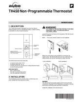
Fig. 1 CT60A, schéma de câblage.
1. Alimentation, fournir, au besoin, un dispositif de coupure et une protection
contre les surcharges.
2. Utiliser des connecteurs sans soudure co/air pour usage spécial si
les conducteurs sont en aluminium. Sinon, il peut Y avoir un risque
d’incendie.
3. L1T1 ferme lors d’une baisse de température.
L1
L2
T1
T2
12
3
MF35685
L1
(CHAUD)
L2
APPAREILDE
CHAUFFAGE
CONNECTEURS
SANSSOUDURE
FIL
HOUGE
CT60B
Fig. 2 CT60B schéma de câblage.
1. Alimentation, fournir, au besoin, un dispositif de coupure et une protection
contre les surcharges.
2. Utiliser des connecteurs sans soudure co/air pour usage spécial si les
conducteurs sont en aluminium. Sinon, il peut y avoir un risque d’incendie.
3. L1T1 ferme lors d’une baisse de température. L2T2 ouvre seulement à la
position d’arrêt.

10
Vérification
1. Tourner le bouton de réglage du point de consigne dans le sens
antihoraire ( ) jusqu’au bout.
2. Remettre le circuit d’alimentation sous tension.
3. Tourner le bouton de réglage du point de consigne dans le sens horaire
() jusqu’au bout; vous devriez entendre un déclic au moment ou le
contact se ferme. La plinthe devrait se réchauffer en 2 à 10 minutes.
4. Tourner le bouton de réglage du point de consigne dans le sens
antihoraire ( ) jusqu’au bout. Vous devriez entendre un dédie au
moment où le contact s’ouvre. La plinthe devrait s’eteindre et commencer
à refroidir.
5. Régler le point de consigne à la température voulue.
Dépannage
Le thermostat exige peu ou pas d’attention. La plupart des problèmes sont
décrits au tableau qui suit :
Symptômes Vérifications Mesure à prendre
Pas de chaleur Le fusible a fondu ou le
disjoncteur est dèclenchè
Remplacer fusible ou rèenclencherle
disjoncteur
Mauvais raccordement
au thermostat
Mettre le thermostat hors thensionet
verifier si la raccordement correspond au
schèmaci- joint
Autre S’adresser a un technicien qualifiè
La plìnthè chauffe
constamment
Tourner le bouton de
reglage du point de
consigne dans le sens
anit-horaire ( ).
1. La plinthe devrait commencer à
refroidir en 2 à 10 minutes.
2. Si la pinthe ne refroidit pas, mettre le
circuit d’alimentation principal hors
tension et vèrifier si la raccordement
correspond au schèma.
Autre Sàdresser à un technicien qualifié

11
Garantie limitée d’un an
Resideo garantit ce produit, à l’exception des piles, contre tout défaut de pièce ou de main-d’oeuvre, durant une
période d’un (1) an à partir de la date d’achat par le consommateur d’origine si le produit est utilisé et entretenu
convenablement. En cas de défaillance ou de mauvais fonctionnement pendant la période de garantie, Resideo
remplacera ou réparera le produit, à sa discrétion.
Si le produit est défectueux
(i) renvoyez-le avec la facture ou une autre preuve d’achat date au lieu d’achat; ou
(ii) appelez le service à la clientèle de Resideo en composant le 18004681502. Le service à la clientèle
déterminera si le produit doit être retourné à l’adresse suivante : Resideo Return Goods, 1985 Douglas Dr. N., Golden
Valley, MN 55422, ou si un produit de remplacement peut vous être expédié.
La présente garantie ne couvre pas les frais de retrait ou de réinstallation. La présente garantie ne s’applique pas
s’il est démontré par Resideo que la défaillance ou le mauvais fonctionnement sont dus à un endommagement du
produit alors que le consommateur l’avait en sa possession.
La responsabilité exclusive de Resideo se limite à réparer ou à remplacer le produit conformément aux modalités
susmentionnées. RESIDEO N’EST EN AUCUN CAS RESPONSABLE DES PERTES OU DOMMAGES, Y COMPRIS LES
DOMMAGES INDIRECTS OU ACCESSOIRES DÉCOULANT DIRECTEMENT OU INDIRECTEMENT D’UNE VIOLATION
QUELCONQUE D’UNE GARANTIE, EXPRESSE OU TACITE, APPLICABLE AU PRÉSENT PRODUIT, OU TOUTE AUTRE
DÉFAILLANCE DU PRÉSENT PRODUIT. Certaines provinces ne permettent pas l’exclusion ou la restriction des
dommages indirects ou accessoires et, par conséquent, la présente restriction peut ne pas s’appliquer.
CETTE GARANTIE EST LA SEULE GARANTIE EXPRESSE FAITE PAR RESIDEO POUR CE PRODUIT. LA DURÉE DE
TOUTE GARANTIE IMPLICITE, INCLUANT LES GARANTIES DE QUALITÉ MARCHANDE OU D’ADAPTATION À UNE
UTILISATION PARTICULIÈRE, EST LIMITÉE PAR LES PRÉSENTES À LA PÉRIODE D’UNE ANNÉE DE LA PRÉSENTE
GARANTIE. Certaines provinces ne permettent pas de limiter la durée des garanties tacites et, par conséquent, la
présente limitation peut ne pas s’appliquer.
La présente garantie donne au consommateur des droits spécifiques et certains autres droits qui peuvent varier
d’une province à l’autre.
Pour toute question concernant la présente garantie, prière d’écrire aux Services à la clientèle de Resideo à l’adresse
suivante : Resideo Customer Relations, 1985 Douglas Dr, Golden Valley, MN 55422 ou composer le 1800468
1502.

33-00145EF-0
3
www.resideo.com
Resideo Inc., 1985 Douglas Drive North
Golden Valley, MN 55422
33-00145EF—03 M.S. Rev. 06-19 | Imprimé aux États-Unis
Ce produit est fabriqué par Resideo Technologies, Inc., Golden Valley, MN, 1-800-468-1502.
© 2019 Resideo Technologies, Inc. La marque de commerce Honeywell Home est utilisée sous licence avec
l’autorisation d’Honeywell International Inc. Tous droits réservés.
/