Task Force Tips HVIT24 Operating instructions
- Type
- Operating instructions

©Copyright Task Force Tips LLC 2001 - 2019 LKR-200 April 22, 2019 Rev04
HAND HELD BALL VALVE &
DETENT STYLE BALL VALVES
SERVICE PROCEDURE
TASK FORCE TIPS LLC
MADE IN USA • TFT.com
3701 Innovation Way, Valparaiso, IN 46383-9327 USA
800-348-2686 • 219-462-6161 • Fax 219-464-7155
D75 SERIES J140 SERIES H-VO SERIES
D100D SERIES J140 SERIES H-2VO SERIES
F100 SERIES H-VIT SERIES H-3VO SERIES
F125 SERIES F140 SERIES HVIT SERIES

©Copyright Task Force Tips LLC 2001 - 2019 LKR-200 April 22, 2019 Rev04
2
DANGER
PERSONAL RESPONSIBILITY CODE
The member companies of FEMSA that provide emergency response
equipment and services want responders to know and understand the
following:
1. Firefi ghting and Emergency Response are inherently dangerous activities
requiring proper training in their hazards and the use of extreme caution
at all times.
2. It is your responsibility to read and understand any user’s instructions,
including purpose and limitations, provided with any piece of equipment
you may be called upon to use.
3. It is your responsibility to know that you have been properly trained in
Firefi ghting and /or Emergency Response and in the use, precautions, and
care of any equipment you may be called upon to use.
4. It is your responsibility to be in proper physical condition and to maintain
the personal skill level required to operate any equipment you may be
called upon to use.
5. It is your responsibility to know that your equipment is in operable
condition and has been maintained in accordance with the manufacturer’s
instructions.
6. Failure to follow these guidelines may result in death, burns or other
severe injury.
FEMSA
Fire and Emergency Manufacturers and Service Association
P.O. Box 147, Lynnfi eld, MA 01940 • www.FEMSA.org

©Copyright Task Force Tips LLC 2001 - 2019 LKR-200 April 22, 2019 Rev04
3
D, F and J Series HAND-HELD BALL VALVES
Intended for use with all ball valves constructed of stainless steel with quick-change rear valve seat.
1.0 ITEMS NEEDED
Not Supplied
In Repair Kit
Bench Vise
Hammer
1/8” Diameter Punch
Safety Glasses
Drill Press (or electric drill)
Loctite 271
2.0 INSTRUCTIONS
1. Remove and discard Hose Gasket (20), Rear Seat (19), and O-ring (18).
2. Open or close bench vise until there is a gap between the jaws of 1/4” to 3/8”. Prop Valve Handle (5) over gap so that Spirol
Pins (5) can be driven into the gap between the vise jaws. Drive out the spirol pins using a 1/8” diameter punch. Note: Do not
use a nail set or pointed punch. This may cause pins to expand, making it very diffi cult to remove. If possible, remove broken
handle at this time. Be sure to wear safety glasses.
3. Pad vise jaws with several rags. Open valve and place repair mandrel through Valve Ball (16). Gently clamp valve in vise with
one Trunnion (2) pointing up. Place allen wrench in end of Trunnion. Unscrew and discard trunnion along with O-ring (3). It may
be necessary to place a piece of pipe or wrench on end of allen wrench for additional leverage.
4. Turn valve over in vise and repeat step #3.
5. Remove valve from vise and remove mandrel, f140 valve coupling (17) will need to be removed, Ball (16), Front Valve Seat
(15), and Belleville Washer (14). Discard Valve Seat and Belleville Washer. Note: Earlier models may have an O-ring in place
of the Belleville Washer.
6. Stand valve vertically on drill press and clamp in vise with coupling end up. Drop Belleville Washer (14) into Valve Body (1)
(note orientation in drawing). Drop Front Valve Seat (15) into Valve Body (1) (note orientation in drawing). Drop Valve Ball (16)
into Valve Body (1) and insert plastic mandrel through hole in ball.
7. Rotate Valve Ball (16) so that threaded holes are aligned with trunnion hole in Valve Body (1).
8. Install O-rings (3) on Trunnions (2).
9. Apply a thin fi lm of grease (supplied) to O-rings and Trunnions, take care not to get any grease on the threads.
10. Apply one large drop of Loctite (supplied) on trunnion threads.
11. Place new Handle (5) in position over Valve Body (1). Make sure that “OFF” on the handle faces the coupling end of the
valve.
12. Insert Trunnions (2) through Handle (5) and Valve Body (1) while pressing down on the plastic mandrel with drill press chuck or
by hand. Note: It will take approximately 50 lb. to compress the Belleville Washer (14). Screw the Trunnion (2) into Valve Ball
(16). Do not tighten yet.
13. Repeat step #12 with other Trunnion.
14. Clamp one allen wrench in vise with approximately 3/8” of the short end above the vise jaws.
15. Place one Trunnion on wrench in vise and second wrench in other Trunnion. The plastic mandrel should still be in the valve
ball. Tighten both Trunnions as tight as you can by hand. Do not use a wrench or pipe on the allen wrench or threads may be
damaged.
16. With the plastic mandrel still in the Valve Ball (16), pull the Handle (5) back to the open or “ON” position. Locate the small dimple
on the Handle (5) above the Trunnions (2). Using the #22 drill (supplied), drill through the dimple, through the center of the
Trunnion (2), and out the other side. Support the Handle (5) below the Trunnions (2) on the edge of the drill press table or on a
pile of boards to insure that the hole passes through the center of the Trunnions (2).
17. Insert the new Spirol Pins (6) in the drilled holes and press, or gently tap them fl ush with the Handle (5).
18. Remove plastic mandrel. Lubricate and install O-ring (18) on Rear Valve Seat (19). Press Valve Seat (19) into Valve Body (1)
(note orientation in drawing). Install new Hose Gasket (20).
If you have trouble, call 1-800-348-2686 for advice or send valve and remaining new parts to our service department. Failure to
follow these instructions, or poor workmanship voids warranty.
* Plastic Repair Mandrels:
3/4” Waterway (D75) - Part number D07535 (Included in repair kit D75-HRK)
1” Waterway (F100) – Part number F10035 (Included in repair kit F100-HRK)
1 1/4” Waterway Exit (F125) - Part number F14035 (Included in the F125-HRK)
1 3/8” Waterway (F140) – Part number F14035 (Included in repair kit F140-HRK)
* Valve Ball (16) and Valve Body (1) are NOT included in repair kits
Exploded view drawings and parts lists on following pages

©Copyright Task Force Tips LLC 2001 - 2019 LKR-200 April 22, 2019 Rev04
4
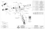
D75 1” BALL VALVE
5
1
14
15
16
18
19
17
20
3
2
6
11
12
13
8
10
9
7
ITEM DESCRIPTION QTY PART #
1* 75 VALVE BODY 1.0" 1 D07520
2 75 TRUNNION 2 D07540
3 O-RING-010 2 VO-010
5 DQ HANDLE SUBASSEMBLY 1 DQ860
DQ860
CONTAINS
75 SHUTOFF HANDLE 1 D07560
BLACK HANDLE COVER 2 HM625-BLK
8-32 X 3/8 BUTTON HEAD SCREW 4 VT08-32BH375
75 STOP PIN 2 D07550
6 SPIROL PIN 2 V1900
7 WASHER 1 VM4901
8 GRIP SPACER D075 1 HM693-D
9 3/8-16 X 1 SOCKET HEAD SCREW 1 VT37-16SH1.0
10 PISTOL GRIP - BLACK 1 HM692-BLK
11 3/8-16 X 5/16 SET SCREW 1 VT37-16SS312
12 PORT PLUG 1 B770
13 3/16" SS BALL 26 V2120
14 BELLEVILLE WASHER 1 D07590
15 75 FRONT SEAT 1 D07570
16 75 BALL 1 D07530
17* COUPLING 1.0" 1 D07597
18 O-RING-120 1 VO-120
19 75 REAR SEAT 1 D07580
20 GASKET - 1.0" 1 V3040
* - STATE DESIRED THREAD WHEN ORDERING

©Copyright Task Force Tips LLC 2001 - 2019 LKR-200 April 22, 2019 Rev04
5
D100D 1” BALL VALVE
6
3
2
8
10
7
9
13
12
11
14
15
16
18
19
20
17
1
5
ITEM DESCRIPTION QTY PART #
1* 100 VALVE BODY 1.0" 1 D10020
2 100 TRUNNION 2 F10040
3 O-RING-012 2 VO-012
5 FQ HANDLE SUBASSEMBLY 1 FQ860
FQ860
CONTAINS
100 SHUTOFF HANDLE 1 F10060
BLACK HANDLE COVER 2 HM625-BLK
8-32 X 3/8 BUTTON HEAD SCREW 4 VT08-32BH375
100 STOP PIN 2 F10050
6 SPIROL PIN 2 V1900
7 WASHER 1 VM4901
8 GRIP SPACER F100 1 HM693-F
9 3/8-16 X 1 SOCKET HEAD SCREW 1 VT37-16SH1.0
10 PISTOL GRIP - BLACK 1 HM692-BLK
11 3/8-16 X 5/16 SET SCREW 1 VT37-16SS312
12 PORT PLUG 1 B770
13 3/16" SS BALL 34 V2120
14 BELLEVILLE WASHER 1 F10090
15 100 FRONT SEAT 1 F10070
16 100 BALL 1 F10030
17* COUPLING 100 1.0" 1 D10097
18 O-RING-126 1 VO-126
19 100 REAR SEAT 1 D10080
20 GASKET - 1.0" 1 V3040
* - STATE DESIRED THREAD WHEN ORDERING

©Copyright Task Force Tips LLC 2001 - 2019 LKR-200 April 22, 2019 Rev04
6
F100 1.5” BALL VALVE
2
3
5
15
16
18
19
17
20
8
11
12
13
7
10
9
1
14 6
ITEM DESCRIPTION QTY PART #
1* 100 VALVE BODY 1.5" 1 F10020
2 100 TRUNNION 2 F10040
3 O-RING-012 2 VO-012
5 FQ HANDLE SUBASSEMBLY 1 FQ860
FQ860
CONTAINS
100 SHUTOFF HANDLE 1 F10060
BLACK HANDLE COVER 2 HM625-BLK
8-32 X 3/8 BUTTON HEAD SCREW 4 VT08-32BH375
100 STOP PIN 2 F10050
6 SPIROL PIN 2 V1900
7 WASHER 1 VM4901
8 GRIP SPACER F100 1 HM693-F
9 3/8-16 X 1 SOCKET HEAD SCREW 1 VT37-16SH1.0
10 PISTOL GRIP - BLACK 1 HM692-BLK
11 3/8-16 X 5/16 SET SCREW 1 VT37-16SS312
12 PORT PLUG 1 B770
13 3/16" SS BALL 34 V2120
14 BELLEVILLE WASHER 1 F10090
15 100 FRONT SEAT 1 F10070
16 100 BALL 1 F10030
17* COUPLING 1.0" 1 F10097
18 O-RING-126 1 VO-126
19 100 REAR SEAT 1 F10080
20 GASKET - 1.5" 1 V3130
* - STATE DESIRED THREAD WHEN ORDERING

©Copyright Task Force Tips LLC 2001 - 2019 LKR-200 April 22, 2019 Rev04
7
F125F & F125FP BALL VALVE
1
10
8
9
7
6
3
2
5
12
13
11
14
15
16
21
19
18
17
20
4
ITEM DESCRIPTION QTY PART #
1* 125 VALVE BODY 1.5" 1 F12520
2 140 TRUNNION 2 F14040
3 O-RING-014 2 VO-014
4 125 STOP PIN 1 F12560
5 125 TAB SHUTOFF HANDLE 2 F12560
6 SPIROL PIN 2 V1920
7 WASHER 1 VM4901
8 GRIP SPACER F140 1 HM693-J
9 3/8-16 X 1 SOCKET HEAD SCREW 1 VT37-16SH1.0
10 PISTOL GRIP - BLACK 1 HM692-BLK
* - STATE DESIRED THREAD WHEN ORDERING
ITEM DESCRIPTION QTY PART #
11 3/8-16 X 5/16 SET SCREW 1 VT37-16SS312
12 3/16" SS BALL 36 V2120
13 1/4-28 X 3/16 SET SCREW 1 VT25-28SS187
14 BELLEVILLE WASHER 1 F14090
15 140 FRONT SEAT 1 F14070
16 140 BALL 1 F14030
17* COUPLING 1.0" 1 F14097
18 O-RING-129 1 VO-129
19 140 REAR SEAT 1.5" 1 F14080
20 GASKET - 1.5" 1 V3130
21 O-RING-140 1 VO-140

©Copyright Task Force Tips LLC 2001 - 2019 LKR-200 April 22, 2019 Rev04
8
F140 1.5” & J140 2.5” BALL VALVE
1
10
8
9
7
6
3
2
5
12
13
11
14
15
16
21
19 18
17
20
17
22
19
18
20
ITEM DESCRIPTION QTY PART #
1* 140 VALVE BODY 1.5" 1 F14020
2 140 TRUNNION 2 F14040
3 O-RING-014 2 VO-014
5 FT HANDLE SUBASSEMBLY 1 FQ860
FT860
CONTAINS
140 SHUTOFF HANDLE 1 F14060
BLACK HANDLE COVER 2 HM625-BLK
8-32 X 3/8 BUTTON HEAD SCREW 4 VT08-32BH375
140 STOP PIN 2 F14050
6 SPIROL PIN 2 V1920
7 WASHER 1 VM4901
8 GRIP SPACER F140 1 HM693-J
9 3/8-16 X 1 SOCKET HEAD SCREW 1 VT37-16SH1.0
10 PISTOL GRIP - BLACK 1 HM692-BLK
11 3/8-16 X 5/16 SET SCREW 1 VT37-16SS312
* - STATE DESIRED THREAD WHEN ORDERING
ITEM DESCRIPTION QTY PART #
12 3/16" SS BALL 36 V2120
13 1/4-28 X 3/16 SET SCREW 1 VT25-28SS187
14 BELLEVILLE WASHER 1 F14090
15 140 FRONT SEAT 1 F14070
16 140 BALL 1 F14030
17* COUPLING 1.0" 1F14097
140 COUPLING 2.5" J14097
18 O-RING-129 1VO-129
O-RING-032 VO-032
19 140 REAR SEAT 1.5" 1F14080
140 REAR SEAT 2.5" J14080
20 GASKET - 1.5" 1V3130
GASKET - 2.5" V3190
21 O-RING-140 1 VO-140
22 O-RING-033 1 VO-033

©Copyright Task Force Tips LLC 2001 - 2019 LKR-200 April 22, 2019 Rev04
9
DETENT STYLE HAND HELD BALL VALVES
This Service Procedure is intended for use with the HVIT, H-VIT, H-VO, H-VOI, H-2VO, H-2VOI, H-3VO, H-3VOI and H-2VPPIT
series of 1.5 and 2.5 inlet Ball Valves.
1.0 ITEMS NEEDED
Not Supplied
In Repair Kit
Bench Vise
T-Handle Allen Wrench Set
Loctite 271
2.0 INSTRUCTIONS FOR VALVE SEAT AND BALL REPLACEMENT
TEAR DOWN:
1. Remove set screws (27) from body that are forward of the bail handle. Grasp the front ring (35, 43, 51, or 78) in padded
vise and remove by unthreading.
2. Remove the valve seat (32 or 75) from the male threaded section.
3. Place the bail handle (16) in the off position and through the female coupling, push the valve ball (33 or 76) out the front of
the valve.
4. Use a straight blade screw driver to remove the rear valve seat (32 or 75).
5. Inspect the o-ring (34 or 77) in the front of the valve for damage and replace if required.
REBUILD SECTION:
6. Place a seat (32 or 75) in the front ring with the male threads.
7. Install valve seat (32 or 75) into the body, fl at side down.
8. Install the ball (33 or 76) with the ID groove facing away from the bail handle side of the valve. If the ball has a turbulence
reduction notch, install the ball with the notch down and towards the bail handle side of the valve.
9. Check for o-ring (34 or 77) in the front of the valve, install front ring (35, 43, 51 or 78) until the shoulder is fl ush with the front
of the body. Compression on the valve is adjusted with the front ring.
10. Cycle bail handle to check for smooth operation. If bail is tight, un-thread front ring. If loose, tighten front ring. Required force
to cycle bail is 3 to 15 lbs.
11. Tighten set screws (27) evenly. If set screws are not tightened evenly there may be a leak around the front ring seal.
12. Place ball valve on a pressurized water system and check for leaks and operation.
3.0 INSTRUCTIONS FOR BAIL HANDLE REPLACEMENT
REMOVAL OF OLD BAIL HANDLE
1. Remove set screws (27) from body that are forward of the bail handle. Grasp the front ring in padded vise and remove.
2. Remove the valve seat (32 or 75) from the male thread section.
3. Place the bail handle (16) in the off position and through the female coupling, push the valve ball (33 or 76) out the front of
the valve.
4. Use a straight blade screw driver to remove the rear valve seat (32 or 75).
5. Inspect the o-ring (34 or 77) in the front of the valve for damage and replace if required.
6. Remove button head screws (19 or 65) from bail handle.
7. Push trunnions (24 or 73) into the valve body and remove. Note: There is a left and right trunnion on this model, do not
mix.
8. Remove bail handle by lifting up off of the valve body. This will release the detent springs and balls.
INSTALLATION OF BAIL HANDLE
1. Insert one Detent Spring (20 or 67) and Detent Ball (21 or 66) into each of the stop lugs of the Bail Handle.
Note: ( Make sure the belly shaped side of the handle faces the front of the valve body.)
2. While holding the detent springs and balls in the stop lugs, push bail handle onto valve body over detent area.
3. Apply lubricant to o-ring (22 or 71) on trunnion.
4. Align the roll pin (17 or 69) with the hole in Bail Handle and push from the inside.
5. Place Trunnion Driver (18 or 70) over roll pins.
6. Apply loctite 271 to the button head screws (19 or 65).
7. Install Button Head screws till tight.
8. Complete steps 6 through 12 in Valve Seat and Ball Replacement Section.
Exploded view drawings and parts lists on following pages

©Copyright Task Force Tips LLC 2001 - 2019 LKR-200 April 22, 2019 Rev04
10
HVIT, H-VIT, H-V0, H-VOI, H-2VO & H-2VOI
36
37 37
39
40
41
38
42 43
44 45
50
46
48
49
51
47
42 43
44 45
52
35
33
34
33
19
20
17
21
22
18
24
23
25
28
29
30
31
32
26
25
27
16
12
11
8
3
3
14
15
13
2
8
9
3
3
2
4
1
56
7
10

©Copyright Task Force Tips LLC 2001 - 2019 LKR-200 April 22, 2019 Rev04
11
ITEM DESCRIPTION QTY PART #
1 GASKET - 1.5" 1 V3130
21/4-28 X 3/16 SET SCREW 1VT25-28SS187 (SWIVEL)
1/4-28 X 3/8 SET SCREW VT25-28SS375 (LOCK-OUT)
3 3/16" SS BALL 38 V2120
4* COUPLING 1.5" 1 H694
5 ANTI GG RING VO 1 P147
6** STREAM STRAIGHTENER 1 P116
7 REDUCTION INSERT F 1 P119F
8 GASKET - 2.5" 1 V3190
9* COUPLING 2.5" 1 P198
10 REDUCTION INSERT J 1 P199J
11 1/4-28 X 1/4 SET SCREW 1 VT25-28SS250
12* COUPLING 2.5" 1 P197
13 O-RING-151 1 VO-151
14 1/4-28 X 3/8 SET SCREW 1 VT25-28SS375
15 BLITZ BASE 2.5 1 H675
16 O-RING-141 1 VO-141
17
HANDLE SUBASSEMBLY 1 HX920
BLACK HANDLE COVER 2 HM625-BLK
HANDLE 1 HX620
8-32 X 3/8 BUTTON HEAD SCREW 4 VT08E32BH375
18 SPIROL PIN 2 V2005
19 TRUNNION DRIVER 2 HX650
20 HANDLE SCREW 2 VT37E24BH750
21 DETENT SPRING 2 HM770
22 .243" TORLON BALL 2 VB243TO
23 O-RING-118 2 VO-118
24 TEFLON TRUNNION SHIM 2 P170
25 TRUNNION - LEFT 1 P120L
TRUNNION - RIGHT 1 P120R
26 DETENT VALVE BODY 1 P110
27 3/8-16 X 5/16 SET SCREW 1 VT37-16SS312
28 10-32 X 3/16 SET SCREW 2 VT10Y32SS187
29 GRIP SPACER HANDLINE 1 HM693-H
30 PISTOL GRIP - BLACK 1 HM692-BLK
31 WASHER 1 VM4109
ITEM DESCRIPTION QTY PART #
32 3/8-16 X 1 SOCKET HEAD SCREW 1 VT37-16SH1.0
33 VALVE BALL SEAT 2 P104
34 DELRIN VALVE BALL 1 P103
35 O-RING-227 1 VO-227
36
FRONT END - 7/8" TIP 1 P181
FRONT END - 15/16" TIP 1 P182
FRONT END - 1.0" TIP 1 P183
FRONT END - 1 1/8" TIP 1 P184
FRONT END - 1 1/4" TIP 1 P185
FRONT END - 1 3/8" TIP 1 P186
37 TEFLON WEAR RING 2 P172
38 VIT FRONT RING LABEL 1 P163
39 CAM SCREW 2 HD780
40 THREAD PROTECTOR RING 1 P175
41 GAUGE BUMPER 1 G262
42 O-RING 123 1 VO-123
43
7/8" SMOOTH BORE INSERT 1 F14031
15/16" SMOOTH BORE INSERT 1 F14032
1" SMOOTH BORE INSERT 1 F14033
1-1/8" SMOOTH BORE INSERT 1 F14034
44* FRONT RING VPP 1.5" 1 P160
45 VH-143-S02 SMALLEY RING 1 V4232
46 BLITZ BRACKET 2 H676
47 1/4-20 SS ACORN NUT 8 VT25E20AC
48 WASHER 8 VW500X265-63
49 1/4-20 X 2 STUD FULL THREAD 4 VT25-20ST2.0
50 PLAYPIPE HANDLE 2 P220
51 SMALL PLAYPIPE BRACKET 2 P210
52* FRONT RING VO 1.5" 1 P150
* - STATE DESIRED THREAD WHEN ORDERING
** - CONTACT TFT FOR USE WITH 2.5” CONNECTIONS

©Copyright Task Force Tips LLC 2001 - 2019 LKR-200 April 22, 2019 Rev04
TASK FORCE TIPS LLC
MADE IN USA • TFT.com
3701 Innovation Way, Valparaiso, IN 46383-9327 USA
800-348-2686 • 219-462-6161 • Fax 219-464-7155
H-3VO & H-3VOI
65
69
67
68
64
26
27
29
30
31
60
61
62
63
3
66
71
72
73
75 76
75
77
78
70
74 73
65
ITEM DESCRIPTION QTY PART #
3 3/16" SS BALL 48 V2120
26 3/8-16 X 5/16 SET SCREW 1 VT37-16SS312
27 10-32 X 1/4 SET SCREW 2 VT10Y32SS250
29 PISTOL GRIP - BLACK 1 HM692-BLK
30 WASHER 1 VM4901
31 3/8-16 X 1 SOCKET HEAD SCREW 1 VT37-16SH1.0
60 GASKET - 2.5" 1 V3185
61 1/4-28 X 1/2 SET SCREW 1 VT25-28SS500
62* COUPLING 2.5" 1 M307
63 TOP BAR 1 P345
64 SIDE BAR 2 P340
65 1/2-13 X 3/4 BUTTON HEAD SCREW 4 VT50-13BH750
66 5/16" TORLON BALL 2 VB.312TO
67 DETENT SPRING 2 P360
ITEM DESCRIPTION QTY PART #
68 STOP LUG 2 P350
69 SPIROL PIN 2 VP250X.625H
70 TRUNNION DRIVER 2 P335
71 O-RING-219 2 VO-219
72 TRUNNION SHIM 2 P330
73 TRUNNION LEFT 1 P325L
TRUNNION RIGHT 1 P325R
74 DETENT VALVE BODY 1 P320
75 VALVE BALL SEAT 2.5" 2 P315
76 BALL VALVE 2.5" 1 P310
77 O-RING-388 1 VO-388
78* FRONT RING VO3 2.5"NH 1 P355
* - STATE DESIRED THREAD WHEN ORDERING
-
 1
1
-
 2
2
-
 3
3
-
 4
4
-
 5
5
-
 6
6
-
 7
7
-
 8
8
-
 9
9
-
 10
10
-
 11
11
-
 12
12


Task Force Tips HVIT24 Operating instructions
- Type
- Operating instructions
Ask a question and I''ll find the answer in the document
Finding information in a document is now easier with AI
Related papers
-
Task Force Tips QuadraCup series Instructions For Installation, Safe Operation And Maintenance
-
-
-
Task Force Tips XGC38VL-PL Operating instructions
-
-
-
Task Force Tips XFT-BJ Operating instructions
-
-
-
Other documents
-
Fluke VT06 Visual IR thermometer User manual
-
Toro Mid-Size ProLine Pistol Grip Hydro, 17 hp w/ 52" SD Mower User manual
-
PowerPlus Energy LiFe Premium Series Operating instructions
-
Craftsman 917255813 Owner's manual
-
Toro 98958SL User manual
-
 AcraDyne AEP4A12003B User manual
-
Toro Commercial Walk-Behind Mower, Floating Deck, T-Bar, Gear Drive User manual
-
Groen TDA Operating instructions
-
Groen TDA/1-40 Operating instructions
-
KTM Ball Valves Series Meta-Seal IOM Owner's manual
