Page is loading ...

Thank you very much for choosing an Ironton Product! For future reference, please complete the
owner’s record below:
Model: _______________ Purchase Date: _______________
Save the receipt, warranty and these instructions. It is important that you read the entire manual
to become familiar with this product before you begin using it.
This trailer is designed for certain applications only. The distributor cannot be responsible for
issues arising from modification. We strongly recommend this trailer is not modified and/or used
for any application other than that for which it was designed. If you have any questions relative to
a particular application, DO NOT use the trailer until you have first contacted distributor to
determine if it can or should be performed on the product.
For technical questions, please call 1-800-222-5381.
WARNING: Read carefully and understand all INSTRUCTIONS before operating.
Failure to follow the safety rules and other basic safety precautions may result in serious
personal injury.
Save these instructions in a safe place and on hand so that they can be read when required.
Keep these instructions to assist in future servicing.
TECHNICAL SPECIFICATIONS
GENERAL SAFETY REGULATIONS
WARNING: Read and understand all instructions. . Failure to follow all instructions
listed below may result in electric shock, fire and/or serious injury.
WARNING: The warnings, cautions, and instructions discussed in this instruction
manual cannot cover all possible conditions or situations that could occur. It must be
understood by the operator that common sense and caution are factors that cannot be built
into this product, but must be supplied by the operator.
• Keep the work area clean and dry. Damp or wet work areas can result in injury.
• Keep children away from work area. Do not allow children to handle this product.
• Always wear ANSI-approved safety glasses and heavy-duty work gloves during assembly
and use. Do not wear loose clothing or jewelry which can get caught in moving parts.
• Check for damaged parts. Before using this product, carefully check that it will operate
properly and perform its intended function. Check for damaged parts and any other conditions
that may affect the operation of this product. Replace damaged or worn parts immediately.
• Do not overreach. Keep proper footing and balance at all times to prevent tripping, falling,
back injury, etc.
• DO NOT use this trailer when tired or distracted.
• Industrial applications must follow OSHA requirements.
5FT. x 8FT. HD TRAILER
WITH 5.30-12 TIRES
OWNER’S MANUAL
5FT. x 8FT. HD TRAILER WITH 5.30-12 TIRES
OWNER’S MANUAL
Item#s 37552
1 of 11
ITEM
Tires
Bed Dimensions
Ball/Coupler Size
Load Capacity
GVWR
DESCRIPTION
5.30-12 Tubeless
5-ft. x 8-ft.
2 Inch
1,715 lbs. max.
1,980 lbs.
WARNING: Read carefully and understand all INSTRUCTIONS
before operating. Failure to follow the safety rules and other basic
safety precautions may resultin serious personal injury.

SPECIFIC OPERATION WARNINGS
•
Before each use, always examine the trailer for proper tire condition and air pressure, damaged
Tail Lights, damaged Side Running Lights, loose bolts and nuts, structural cracks, bends and
any other condition that may affect its safe operation. Do not use the Trailer even if minor
damage appears.
•
Before each use, always attach the Safety Chains of the trailer to the towing vehicle. Make sure
the Safety Chains are attached to the towing vehicle with the equal length at each side. Do
not allow the Safety Chains to drag on the ground.
• Always check to make sure the payload being transported properly and safely secured in the
trailer. Load the Trailer evenly from side to side with 60% of the load forward of the Axle.
• Make sure the towing vehicle is capable of towing this trailer and its payload. Make sure the
hitch on the towing vehicle is capable of towing the Trailer and its payload. The towing
capacity of the hitch is typically stamped on the hitch drawbar.
• Make sure the hitch coupler and the vehicle’s Ball Hitch (not included) are of equal mating
size (2in.) and are rated equal to or greater than the weight of the trailer and its payload.
• Do not exceed 45 miles per hour when towing the trailer. Excess speed is a major cause of
vehicle-trailer accidents.
• The Tail Light Bulbs supplied with this trailer are for a 12 Volt DC electrical system only. Do
not attempt to power the Light Bulbs with any other type or voltage electrical current.
• Whenever possible, park the trailers on a flat, level, paved surface and chock both tires to
keep the trailer from accidently moving.
• Before attempting to fold up the trailer, make sure it is on a flat, level, solid surface and chock
both tires.
• Never attempt to fold up the trailer without assistance.
• DO NOT exceed the 1715 pound weight capacity.
• DO NOT allow anyone to ride in the towed vehicle or on the trailer.
• The coupler must be properly secured to the hitch ball. After assembly and attachment, pull
up and down on the hitch coupler to make sure the hitch ball is snug in the hitch coupler. If
the coupler is not secured properly, it could come loose while the trailer is in motion, causing
property damage, serious personal injury or even death.
• Make wide turns when towing a loaded trailer, avoiding both sharp turns and U-turns. Turning
too sharply can cause damage to the trailer and/or the tow vehicle.
UNPACKING
When unpacking, check to make sure all the parts shown on the Parts List are included. If any
parts are missing or broken, please call the distributor at 1-800-222-5381.
TRAILER ASSEMBLY INSTRUCTIONS
STEP 1:
1. Lay out right & left side rail (#1L, 1R) , four cross member (#2) and center cross member (#3)
as shown.
2. Note: there are 2 small holes and a regular hole on the front end of left and right side rails as
circle A shown, this end must toward the front.
3. Assemble side rail (#1L, 1R ) with cross member and center cross member (#2, 3) using
M10*25 BOLT , 10 FLAT WASHER and M10 NUTS (# A,C,B ) as shown .
4. Bolt front spring hanger (shorter) and rear spring hanger (longer) (#7,8) to side rail by M10*25
SQUARE NET BOLT , 10FLAT WASHER and M10 NUTS (# F,C,B) as shown .
STEP 2:
1. Put leaf spring (#20) on spring hanger (#7,8) with spring eye forward, secure with M14*80
BOLT and M14 NYLON LOCK NUT (#G, H) at front portion, M10*75 BOLT, 10FLAT WASHER
and M10 NUTS (# E,C, B ) at rear portion as shown. (Do not overtighten)
2. Place axle (#10) on the leaf spring (#20). Note: axle with hole base must be downward. The
bolt head of leaf spring insert to the both end holes on axle. Put spring plate (#18) under leaf
spring (#20), using “U “bolt (#19) pass through axle (#10), leaf spring (#20) and hole of spring
plate (#18), then lock with 10FLAT WASHER (# C ) and M10 NUTS (# B ) as shown .
3.Attach both tire/hub (#12, 26) assemblies to axle (#10) by sliding hub (wheel studs pointed
outward ) over spindle. Slide outer bearing (#27) on to spindle and into bearing cap in hub
(#26). Secure hub with HUB FLAT WASHER (#U) and castle nut (#28), tighten them snugly.
Note: Back off castle nut (#28) slightly so that hub can spin freely.
5FT. x 8FT. HD TRAILER WITH 5.30-12 TIRES
OWNER’S MANUAL
5FT. x 8FT. HD TRAILER WITH 5.30-12 TIRES
OWNER’S MANUAL
2 of 11 3 of 11

4 of 11 5 of 11
4. Insert COTTER PIN (#T) through the hole at the end of spindle
and bend pin over to lock. Gently tap dust cap (#29) over hub
opening until flange on cap seats on hub .
STEP 3:
1. Attach tow bar (#5) to side rail (#1L, 1R) to cross member (#2). Note: tow bar with three holes
is toward the front. Secure with M10*25 BOLT, 10FLAT WASHER and M10 NUTS (# A,C,B )
as shown.
2. Place stand base (#16) on the front of tow bar (#5), secure with six holes by M10*25 BOLT,
10FLAT WASHER and M10 NUTS (# A,C,B ) as shown.
5FT. x 8FT. HD TRAILER WITH 5.30-12 TIRES
OWNER’S MANUAL
5FT. x 8FT. HD TRAILER WITH 5.30-12 TIRES
OWNER’S MANUAL
STEP 4:
1. Turn over the trailer assembly.
2. Attach spare tire bar (#6) to the “U “ channel of tow bar and put the coupler base (#15) on the
tow bar as shown, secure with M10*25 BOLT, 10FLAT WASHER and M10 NUTS (# A,C,B ) .
3. Install coupler (#14) to coupler base (#15). Attach safety chain (#17) to the coupler (#14) with
an M12*40 bolt inserted through the center link of the safety chain in place, using a 12 flat
washer and M12 nylon nut (#O,L,K). Using two M12*90 BOLT go through the side wall hole of
coupler and coupler base then lock with M12 FLAT WASHER and M12 NYLON LOCK NUT (#I,
L, K) as shown. Insert M12*20 BOLT with M12 FLAT WASHER to the top hole of coupler (#14)
then lock with M12 NYLON LOCK NUT (#J, L, K ). Place coupler with coupler base (#14, 15)
on the front of the tow bar, secure with six holes by M10*25 BOLT, 10FLAT WASHER and
M10 NUTS (# A,C,B ) as shown.
4. Lock coupler trigger using safety pin (#N) through the trigger
hole then insert the 2mm R pin (#Q) through the end hole of
safety pin (#N) to lock the coupler.
STEP 5:
1. Mount fender bracket A (#30) to the left side rail (#1L) using M10*25 BOLT , 10FLAT
WASHER and M10 NUTS (# A,C,B ) and mount fender bracket B (#31) to the right side rail
(#1R) using M10*25 BOLT , 10FLAT WASHER and M10 NUTS (# A,C,B ) as shown. Note:
Fender bracket A and B are mirror image each other. Install fender (#11) to fender bracket A
and B (#30,31) using M10*25 BOLT , 10FLAT WASHER and M10 NUTS (# A,C,B ) as shown .
2. Tighten the M12 HUB LUG NUT (#M) with socket or lug wrench to 90 ft/lbs.
Caution: Periodically add grease as needed to the grease fitting.

6 of 11 7 of 11
5FT. x 8FT. HD TRAILER WITH 5.30-12 TIRES
OWNER’S MANUAL
STEP 6
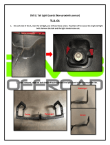
1. Assemble tail light bracket (#23) to the end of left and right side rail (#1L, 1R) using M10*25
BOLT, 10 FLAT WASHER and M10 NUTS (#A,C,B). Install license plate holder (#13) with left
tail light (#21) to left side rail (#1L) using supplied hardware. Note: Left tail light is with a clear
window. Install right tail light (#22) to right side rail.
2. Open the lens of side running light (#25) by coin with 4mm self tapping screw (#S) and run
wire lead through the center hole to find wire to side rail then cover with the lens .
5FT. x 8FT. HD TRAILER WITH 5.30-12 TIRES
OWNER’S MANUAL
TRAILER LIGHT AND WIRE ASSEMBLY INSTRUCTIONS
WIRING DIAGRAM AND INSTRUCTION
1.
Check alignment of all parts and install the 4-wire vehicle connector in the trunk area of your car.
2. Locate the connector plug near the hitch ball and lay out wires.
3. Connect the white wire to the frame or body of the car;
4.
Connect the brown wire to the tail light by stripping, wrapping, and taping connector; similarly
connect the yellow wire to the left signal and stop light wire and the green wire to the right
signal and stop light wire. NOTE: Some foreign vehicles may require an adapter to convert
their 5-wire system to the wire vehicle connector.
1. Attach white ground wire at plug end of wiring harness to the small hole on coupler base
(#15) with 4mm tapping screw.
2. Leave about 18” of wire beyond the coupler and lay out wire on the inside to the channel of
tow bar and side rail as shown. Holes wire to rail with wire clip as circle D.
3. Connect the wire lead from the side running light to the brown wire on each side with the wire
connector. Use pliers to squeeze the connector closed as circle E.
Strip end of wire 3/4” for yellow / brown and green / brown wires.
Make tail light connections as per color code with connector as circle C .
Left Side
Yellow – Red wire
Brown – Two black wires
Right Side
Green – Red wire
Brown – Two black wires

8 of 11 9 of 11
5FT. x 8FT. HD TRAILER WITH 5.30-12 TIRES
OWNER’S MANUAL
SAFE USE AND OPERATION RULES
1. TOWING VEHICLE
• Make sure vehicle is capable of towing the load.
• Excess speed is the second highest cause of car-trailer accidents. Recommended maximum
speed for all passenger cars towing trailers is 45 MPH.
2. HITCH, BALL, COUPLER
• Check that the hitch on the towing vehicle is capable of towing the trailer. The towing
capability of the hitch is normally stamped on the hitch drawbar.
• Make sure the coupler and the ball are the same sizes and are rated equal to or greater than
the load.
• Never attach anything other than the proper size coupler to the ball for towing.
• CAUTION: Care must be taken when backing up the Trailer; only back up the trailer on a
straight path. If the Trailer is allowed to turn off the straight path while backing up, the Trailer
could jackknife, causing sever damage to the trailer and to the towing vehicle.
3. SAFETY CHAINS:
• Be sure to use safety chains.
• Check that the safety chains are attached to towing vehicle with the safety chains the same
length for each side.
• Do not allow chains to drag on the ground.
4. LOADING:
• Never overload the trailer. Maximum load is 1715LBS.
• Load trailer evenly from side to side with 60% of the load
forward to the axle. It is important that the tongue be
pressing down on the hitch, but not exceeding a
downward force of 1715 lbs.
• Reduce weight in car trunk
and rear seat areas by amount
of tongue weight of your trailer.
• It is against the law to carry passengers in any trailer.
5. LIGHTING:
• Check lighting before each use and every 100 miles to be sure the stop, tail, and turn signals
are working properly. REPLACE ANY BROKEN LENSES, REFLECTORS, OR BULBS.
• Check wires for good connections and possible fraying or wearing of insulation.
• Bulbs supplied with this trailer are for 12-volt systems.
• Bulbs used in tail light are: Number – 1157 – Stop and Tail.
• Bulb for clearance is: Number – 194.
6. TIRES:
• Check tires for wear and proper inflation before each use and every 100 miles.
• Tire pressure should be kept at 60 PSI.
• Check and tighten lug nuts. Torque to 85-90 FT-LBS.
• Re-torque after first 50 miles.
7. OPERATION:
• Know how to properly control your towing vehicle – trailer combination on the highway under
all conditions. Remember the loaded weight of the trailer will increase your braking and
stopping distances appreciably.
5FT. x 8FT. HD TRAILER WITH 5.30-12 TIRES
OWNER’S MANUAL
• When towing a trailer over long distances, stop and check the tightness of all connections,
lights, and running gear every 100 miles.
• Carry emergency flares, and fire extinguisher if required for operation in your state.
• It is recommended to carry extra bulbs and fuses if you are towing the trailer at night over any
great distance.
8. MAINTENANCE
• Check and maintain the trailer, coupler, ball and hitch before each use and every 200 miles.
• Inspect coupler, hitch and ball for damage before each use.
• Ball or hitch can be damaged in parking, hitting curbs, dragging when crossing ditches or
railroad tracks.
• Check safety chains and hooks for wear and do not allow safety chains to drag on ground.
• To prevent bearing damage, disassemble and repack wheel bearing with a good grade of
wheel bearing grease every 2000-3000 miles or yearly.
• If you do not know how to repack wheel bearing, take your trailer to a qualified technician.
SPECIAL NOTICE FOR COUPLER
1. Only use a 2” ball hitch (not included) on the towing vehicle.
2. Temporarily remove the “R” Pin and Safety Pin. Then, pull up on the Trigger and lift up on
the Handle.
3. NOTE: To reduce friction between the hitch ball and Coupler, apply a layer of heavy weight
grease over the hitch ball.
4. With assistance, place the Coupler over the vehicle’s hitch ball and pull back on the Trigger
and push down on the Handle until the Trigger locks in the slot. Pull up and down on the
Coupler to make sure the hitch ball is fitting snuggly in the Coupler. There should be no play
between the hitch ball and Coupler.
IMPORTANT: If there is play, tighten the Adjustment Nut until no play is present – after
unlocking the handle, the Nut retaining plate (holding the adjusting nut in place) needs to be
pressed back while the nut is tightened. After Nut is tightened, the retaining plate needs to be
fit in place against the flats of the Nut to prevent it from moving. This adjustment should be
done by two people. If the Adjustment nut is too tight, the Handle will not lock.
After the Adjustment Nut is properly adjusted, pull back on the Trigger and push down on the
Handle until the Trigger locks in the slot. Pull up on the Handle firmly to make sure the Trigger is
locked in place and the Handle cannot move. Replace the Safety Pin and the “R” Pin.

10 of 11 11 of 11
5FT. x 8FT. HD TRAILER WITH 5.30-12 TIRES
OWNER’S MANUAL
DIAGRAMS AND PARTS LIST
Note: Some parts and hardware are listed for illustration purposes only, and are not available
individually as replacement parts.
Part No.
A
B
C
E
F
G
H
I
J
K
1L
1R
2
3
5
6
7
8
10
11
12
13
14
15
16
Description
M10*25 BOLT
M10 NUTS
10FLAT WASHER
M10*75 BOLT
M10*25 SQUARE NET BOLT
M14*80 BOLT
M14 NYLON LOCK NUT
M12*90 BOLT
M12*20 BOLT
M12 NYLON LOCK NUT
LEFT SIDE RAIL
RIGHT SIDE RAIL
CORSS MEMBER
CENTER CROSS MEMBER
TOW BAR
SPARE TIRE BAR
FRONT SPRING HANGER (shorter)
REAR PRING HANGER (longer)
AXLE
FENDER
TIRE/WHEEL ASSY
LICENSE PLATE HOLDER
2” COUPLER
COUPLER BASE
STAND BASE
Qty.
54
72
72
2
8
2
2
2
1
4
1
1
4
1
2
1
2
2
1
2
2
1
1
1
1
Part No.
L
M
N
O
Q
R
S
T
U
17
18
19
20
21
22
23
25
26
27
28
29
30
31
Description
M12 FLAT WASHER
M12 HUB LUG NUT
COUPLER SAFETY PIN
M12*40 BOLT
R PIN
GREASE FITTING
SELF TAPPING SCREW
COTTER PIN FOR SPINDLE
HUB FLAT WASHER
SAFETY CHAIN
SPRING PLATE
U BOLT
LEAF SPRING
LEFT TAIL LIGHT
RIGHT TAIL LIGHT
TAIL LIGHT BRACKET
SIDE RUNNING LIGHT
HUB SET
BEARING
CASTER NUT
DUST CAP
FENDER BRACKET A
FENDER BRACKET B
Qty.
4
10
1
1
1
2
4
2
2
1
2
4
2
1
1
2
2
2
2
2
2
2
2
5FT. x 8FT. HD TRAILER WITH 5.30-12 TIRES
OWNER’S MANUAL
IMPORTANT
The purpose of the following notices is to give you tips on safe use and operation of your utility
trailer.
1. Please read the instructions carefully and follow them step-by-step for easy assembly.
Please keep this instruction.
2. Please double check the assembling step-by-step to be sure each is followed.
3. Before using, please inspect your trailer.
4. Do not remove the VIN sticker from the tow bar.
NOTICE:
• Re-fill grease on bearing after every 3,000 miles of use.
• Keep tire pressure at 60 PSI, cold.
• Please insure that you comply with the following before using your trailer:
1. Tighten U-bolt.
2. Tighten lug nuts.
3. Tighten trigger lock on coupler.
4. Hook up safety chain.
5. Trailer load should not exceed its 1,715 LB capacity and should be properly secured.
6. Trailer load size should not exceed trailer’s bed board size.
TRAILER LICENSING NOTICE:
Some states may consider that this trailer kit is and specially constructed or a homemade
vehicle for registration, licensing and/or titling purposes.
The M.C.O. (Manufacturer’s Certificate of Origin) supplied with your trailer must be filled out and
signed by the dealer transferring ownership to you.
When licensing your trailer, you will need the signed M.C.O., a purchase invoice, cash register
receipt, or bill of sale showing the purchase and retail sales tax or use tax collection by the
retailer. Take these to your local Department of Motor Vehicles and upon payment of the
appropriate State fees, you will be issued a title, registration and license plate (if required).
Some states will require inspection of the assembled and finished trailer kit before issuing a title
registration/license.
If you require additional information or guidance on licensing or titling, please consult your
State Department of Motor Vehicles.

5FT. x 8FT. HD TRAILER WITH 5.30-12 TIRES
OWNER’S MANUAL
Reporting Safety Defects
If you believe that your vehicle has a defect which could cause a crash or could cause injury or
death, you should immediately inform the National Highway Traffic Safety Administration
(NHTSA) in addition to notifying the distributor.
If NHTSA receives similar complaints, it may open an investigation, and if it finds that a safety
defect exists in a group of vehicles, it may order a recall and remedy campaign. However, NHTSA
cannot become involved in individual problems between you, your dealer, or Northern Tool &
Equipment Company, Inc.
To contact NHTSA, you may call the Vehicle Safety Hotline toll-free at 1–888–327–4236 (TTY:
1–800–424–9153); go to http://www.safercar.gov; or write to:
Administrator, NHTSA
1200 New Jersey Avenue SE.
Washington, DC 20590.
You can also obtain other information about motor vehicle safety from http://www.safercar.gov
WARRANTY
One-Year Limited Warranty
Distributed by
Northern Tool + Equipment Co., Inc.
Burnsville, MN 55306
NorthernTool.com
Made in China
/