Page is loading ...

Model TOX-O
2
/ANA Oxygen Gas Sensor (3/07)
TOX-O
2
/ANA SERIES
MODELS:
TOX-O
2
/1 & TOX-O
2
/4
OXYGEN GAS TRANSDUCER
4 To 20 mA
Toxalert model TOX-O
2
/ANA sensor/transducers have a range of 0 to 25 % and outputs a
linear 4 to 20 mA signal or 0 to 5 VDC over its range.
Model Description
Tox-O
2
/1 4 to 20 mA output
Tox-O
2
/4 4 to 20 mA output & relay
This manual is intended for the installer and user to produce a well installed system and
insure the owner/user of a well operating system for years to come.

Model TOX-O
2
/ANA Oxygen Gas Sensor (3/07)
TOXALERT INTERNATIONAL, INC.
Phone: (952) 472-4541 REVISED
Fax: (952) 472-4960 MARCH 2007
=======TABLE OF CONTENTS======
SECTION PAGE
BACKGROUND 1
PRODUCT FEATURES 2
PRODUCT DESCRIPTION 3
CAUTIONS; WARNINGS & RECOMMENDATIONS
2.1 Introduction 5
2.2 Wiring 5
2.21 Power 6
2.3 Sensor Modules 6
2.4 Oxygen Deficiency Hazards 7
INSTALLATION
3.1 Sensor Mounting 7
3.2 Sensor Location 9
3.3 Sensor Installation 9
3.4 Loop-up LED 10
CALIBRATION
4.1 Calibration Quick Check 10
4.2 Calibration Procedure 11
OPERATION
5.1 Signal Value 12
SERVICE
6.1 General 13
6.2 Sensor Replacement 13
SPECIFICATIONS 13
7
ACCESSORIES & SPARE PARTS 14
8
WARRANTY 14
9
RELAY ADJUSTMENT PROCEDURE 15
(For model TOX-O
2
/4)
10

Model TOX-O
2
/ANA Oxygen Gas Sensor (3/07)
BACKGROUND:
Industries have long used oxygen sensors to monitor for the lack of oxygen when
industrial gases could displace the oxygen in air and cause possible asphyxiation.
Applications include refrigerant leak in mechanical rooms, MRI rooms and nitrogen
storage rooms.
Typical alarm levels for oxygen depletion monitors are 19.5% oxygen depletion for the
first stage and 18.5% oxygen depletion for the alarm stage.
Page 1

Model TOX-O
2
/ANA Oxygen Gas Sensor (3/07)
PRODUCT FEATURES
Features of the Toxalert Oxygen sensor that make it stand out above competitive
equipment.
1.) Sensing element life: 10 years in normal service.
2.) Explosion proof housing.
3.) Response time: 10 seconds to 90% of change.
4.) Linear 4 to 20 mA output signal over range
5.) Light emitting diode (LED) indicators:
a.) Power to sensor
b.) Sensor failure LED
c.) Loop current indicator: lights with varying intensity when
4 to 20 mA sensor output current is flowing.
Other features:
1.) Low voltage circuits.
2.) Meets ASHRAE Std. 15, 1994.
3.) Interfaces directly to DDC control systems.
4.) Low power consumption-less than one watt.
5.) Field replaceable sensing element.
6.) Easy calibration and calibration check.
Page 2

Model TOX-O
2
/ANA Oxygen Gas Sensor (3/07)
1. PRODUCT DESCRIPTION
1.1 Introduction
The Model Tox-O
2
/1 Oxygen Deficiency Gas Sensor/Transducer is designed for use in
conjunction with Toxalert and other industry standard 4-20 mA controllers. The module
requires a three wire connection. Two wire 24 VDC power (8.5 to 26.4 VDC Maximum)
and one wire signal.
DO NOT APPLY OVER 26.4 VDC POWER.
The model Tox-O
2
/1 output current is a linear 4 to 20 mA signal over its 0 to 25 %
oxygen range.
1.2 Application
The Model Tox-0
2
/ANA Oxygen Gas sensor is intended for use in ambient monitoring
applications. It is designed for fixed installation and for continuous operation.
The Tox-0
2
/ANA is used to monitor for low oxygen levels because of displacing gases.
1.3 Configuration
The gas transducer is comprised of a NEMA-7 enclosure which contains the transmitter
electronics and a gas sensor which is installed in one of the two 3/4" conduit hubs.
Page 3

Model TOX-O
2
/ANA Oxygen Gas Sensor (3/07)
1.4 Electronics
When installed, the transmitter electronics will be connected to a Toxalert controller or a
Customer provided power supply and control device via three wire cable.
The electronics provide a linear 4-20 mA current which is proportional to the full scale
sensitivity of the sensor. Integral features include:
--Volt meter readout terminals proportional to concentration,
--Visual indicators for fault condition and sensor power,
--4 to 20 mA loop current indicator to indicate when output loop current is
flowing.
1.5 Sensor
The gas sensor is an electrochemical cell with extremely long life. The sensor element is
the self-powered, diffusion limited, metal-air battery type. The rate at which atmosphere
gases can get to the electrode through diffusion barrier is dependent on the concentration
of gases (O
2
in this case) in the ambient atmosphere. A voltage is generated that is
proportional to the rate of consumption of oxygen in the sensor cell.
Most electrochemical sensors use a very thin plastic membrane and have a short life. The
Toxalert oxygen sensor uses a heavy membrane which allows gas to diffuse into the
sensor making it extremely robust and stable, plus it gives the element exceptionally long
life, but still responds quickly to oxygen content changes.
Page 4

Model TOX-O
2
/ANA Oxygen Gas Sensor (3/07)
2. CAUTIONS; WARNINGS & RECOMMENDATIONS
2.1 Introduction
Although the sensor module is designed and constructed for installation and operation in
industrial applications including "hostile" environments, caution should be taken to
insure that the installation is in compliance with this instruction manual and that certain
procedures and conditions are avoided.
READ AND UNDERSTAND THIS INSTRUCTION MANUAL BEFORE
OPERATING OR SERVICING THIS EQUIPMENT.
2.2 Wiring
Electro magnetic and radio frequency interference to the analog communication between
the sensor and the controller can occur. The manufacturer recommends that extra caution
be taken where the installation is near any sources of these interferences.
Avoid running sensor cable close to high power cables, radio transmission lines, or cables
subject to pulses of high current. Avoid running cables near large electric motors or
generators.
If the facility has variable frequency drives (VFD's) to operate fan or pump motors, make
sure that these are wired per the manufacturers instructions. Most VFD manufacturers
recommend that the power to the VFD and the VFD output be in separate, grounded,
metallic conduits. The input and output conduits should have NO other wire running in
these conduits because of the high RFI generated by the VFD if other wiring is run in
these conduits, it can transmit RFI signals throughout the entire complex possibly causing
many problems.
Use shielded cable in any location which may be expected to be electrically noisy or
where cable is expected to be in close contact with AC wiring. The shield should be
connected to the controller common, one end only.
The wiring should be run in either a cable tray or conduit as required by applicable code
and area classification. Control wiring should not be installed in a cable tray or conduit
with higher voltage and AC circuits. See Table 2 for recommended wire gauge.
NOTE: Because of the inherent low impedance of 4 to 20 mA circuits, nominally
about 250 ohms, the 4 to 20 mA circuits tend to pick up less stray noise (RFI) than
do higher impedance voltage input circuits.
Page 5

Model TOX-O
2
/ANA Oxygen Gas Sensor (3/07)
Wiring connections at the gas sensor module are as follows:
Table #1
Function Terminal J2
Power #1
Signal #2
Common (GND) #3
2.21 Power:
Power the sensor with 8.5 to 26.4 VDC (Nominal of 24 VDC.) DO NOT POWER WITH
HIGHER THAN 26.4 VDC. Sensor requires less than one watt of power at 24 VDC.
(w/max drop of 4 volts in run.)
Connect an earth ground to the ground screw provided in the base of the gas sensor
module enclosure. All splices must be via either a lug and terminal system or soldered.
Improperly spliced cable can result in corrosion, resistance changes and system errors.
NOTE: Temperature rating of cable wire insulation must be above 75 degrees C
(85 degrees C or greater rated wiring is recommended.) If cable runs through
higher temperature environments, it should be specified for that environment.
.
NOTE: The smaller the wire gauge used for the sensor installation the easier it will
be to wire and replace the electronics back in its housing.
2.3 Sensor Modules-General
Avoid installing sensor modules where they will be unnecessarily exposed to wind, dust,
water (esp. direct hose down), shock, or vibration. Observe temperature range
limitations.
Sensors may be adversely affected by prolonged exposure to certain materials. Loss of
sensitivity, or corrosion, may be gradual if such materials include: Halides (compounds
containing chlorine, fluorine, bromine, or iodine), acid vapors, caustic liquids or vapors.
Page 6

Model TOX-O
2
/ANA Oxygen Gas Sensor (3/07)
Sensor modules must not be painted. Paint may contain compounds which will
contaminate the sensor. Paint will also cause clogging of the sintered metal cup that
covers the sensing element and will cause difficulties during attachment of the calibration
head. The module should be tagged "DO NOT PAINT".
When sensor element is replaced the thread on the sensor housing must be Teflon taped
to avoid metal to metal binding which will damage the housing threads.
2.4 Oxygen Deficiency Hazards
ASHRAE 15-1992 rule 3(d) reads:
"(d) detectors are located in areas where refrigerant vapor from a leak is likely
to concentrate to provide an alarm at the following levels: Group A1, below 19.5% volume
oxygen; Groups A2 and A3, at levels listed in Table 1; and Groups B1, B2, and B3 (except
ammonia), no higher than their TLV (or toxicity measure consistent therewith)".
2.5 Preventative Maintenance
DUST AND DIRT CONTROL: When calibration is performed the controller and
sensors should be checked visually to determine if dust or dirt build up needs to be
removed. This cleaning should be done with dry instruments such as compressed air,
cloth wipes or whisk broom.
WIRING OR CABLE CONDITIONS: Any wiring or cables which are not in conduit
should be checked once a year for damage to insulation or corrosion of splice or terminal
points.
3. INSTALLATION
3.1 Sensor Mounting
Mount the sensor on a wall in the vertical position with the sensor element pointing down
only. See figure 1.1 in this manual.
Page 7

Model TOX-O
2
/ANA Oxygen Gas Sensor (3/07)
Page 8

Model TOX-O
2
/ANA Oxygen Gas Sensor (3/07)
3.2 Sensor Locations
Select locations for each of the sensors based on the following:
Consider the density of the displacement gas to determine height of sensor above
floor or ground level. Most Group A1 Hydrocarbon based refrigerants are heavier
than air; therefore the oxygen sensor or refrigerant sensor should be mounted
within 18 inches of the floor "in an area where refrigerant from a leak will
concentrate."
Sensors must be pointed down and the conduit should include an inverse trap to
reduce moisture (condensation) from accumulating in the electronics enclosure.
(See fig. 3.1)
3.3 Sensor Module Installation
1. Remove the sensor electronics (figure 3.2) from the module enclosure by:
a. Unscrew the two captive panel screws in the top plate.
b. Lift the electronics out of the enclosure.
c. Disconnect the red and black sensing element leads from J1 terminal strip.
(Note terminal block identification J1, J2, J3 J4 in the bottom of sensor housing. This
label also gives terminal numbers 1,2,3 for each block.) The Tox-0
2
/1does not include
terminal blocks J3 and J4.
2. Install the module housing onto the end of the supply conduit and bolt into position as
required.
NOTE: If enclosure grounding is required for the installation a threaded lug is
located under the printed circuit assembly inside the enclosure and another is
located outside the housing near the conduit inlet. A screw is provided inside the
housing.
3. Connect the three (3) wires which run from the controller to the three position
terminal strip, J2, on the bottom of the electronics assembly. See figure 3.2. A label
glued in the bottom of the sensor housing also indicates which terminal strip is J1 and J2.
The label also indicates terminal numbering and identifies which wire goes where. Also
reference figure 3.2 in this manual.
4. Reconnect the sensing element leads to the sensor connector on the bottom of the
electronic assembly. Figure 3.2.
Twist the assembly 180 degrees to take up the service loop on both the incoming wire
and the sensor harness. Carefully fit the electronics over the two posts in the enclosure
and tighten the captive panel screws.
Page 9

Model TOX-O
2
/ANA Oxygen Gas Sensor (3/07)
3.4 "Loop Up" LED
The loop-up light emitting diode (LED) is in series with the 4 to 20 mA output signal.
The LED is intended to indicate communications with its controller. When signal is
normal and in communications with the controller, the LED will be lighted green. If
LED is out (not lighted) it indicates an open circuit. The loop-up LED will not operate on
0 to 5 VDC models.
4. CALIBRATION
4.1 Tox O
2
/ANA Sensor Calibration--a quick check.
A quick calibration check should be done on the O
2
sensor every six (6) months.
The Tox-O
2
/ANA is a very stable sensor and monthly calibration is not required.
However, if this units operation is in question, a simple calibration check may be
performed.
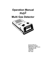
To check calibration remove the cover, take a digital voltmeter and plug the voltmeter
positive (+) lead into the sensor (+) cal signal socket and the voltmeter negative (-) lead
into the sensor (-) cal signal socket. When the sensor is exposed to normal air the digital
voltmeter should read 0.1741 vdc. The digital voltmeter reading will give you the
oxygen concentration (to which the sensor is exposed) by referencing the label inside the
sensor cover.
Example: 0.1741 vdc = 20.95%, which is the normal oxygen content of air. If the sensor
needs calibration, simply insert a small screwdriver into the span pot and turn the span
pot clockwise/counter-clockwise until the meter reads the correct voltage.
Remove the voltmeter and close the module enclosure.
+
-
CAL
SIGNAL
POWER
ON
DISCONNECT SYSTEM
POWER BEFORE
SERVICING
SPAN
ZERO
MODEL
S/N
FIGURE 4.1
FAULT
LOOP
UP
SENSOR
Page 10

Model TOX-O
2
/ANA Oxygen Gas Sensor (3/07)
4.2 Calibration Procedure: If there is reason to believe sensor needs complete
calibration, proceed with the following.
Use Figure 4.1 to identify the test points and adjustments referenced in this procedure.
The zero adjustment does not require calibration, but if sensor needs total calibration, a
calibration kit will be required with adapter, pressure regulator, flow regulator, on/off
valve, tank of zero gas (nitrogen) and tank of span gas (air). The nitrogen zero gas is
provided to verify output signal to controller and test the sequence of operation.
If unit is in known good air which is absent of any refrigerants or other asphyxiant
chemicals the voltmeter should read .1741 volts which indicates 20.95% oxygen. If
voltmeter reads something different, adjust the SPAN Pot to read .1741 volts. If the
ambient air is suspect, connect the span gas (air) to the sensor and allow gas to flow for 2
minutes before trying to adjust the span pot. Adjust the span pot to read .1741 volts. The
calibration is now complete. Remove the gas sample and the voltmeter. Replace the
sensor cover.
Page 11

Model TOX-O
2
/ANA Oxygen Gas Sensor (3/07)
5. OPERATION
5.1 Signal Value
The Model Tox-O2/1/A is a linear 4 to 20 mA signal over the sensors range. At
0% oxygen the sensor will output 4 mA or 0 vdc; at 25% oxygen the sensor will output
20 mA or 5 vdc. To make field calibration and systems checkout easier, we provide a
voltage signal, across the (+) and (-) "Cal Signal" terminals on the face of the sensor
under the screw on/off cover.
=====Percent Oxygen vs Sensor output Signal=====
Tox-O2/1/A
Oxygen CAL signal ma output
0% 0.0400V 4 mA
5% 0.0720V 7.2 mA
10% 0.1040V 10.4 mA
15% 0.1360V 13.6 mA
16% 0.1424V 14.24 mA
17% 0.1488V 14.88 mA
18% 0.1552V 15.52 mA
18.5% 0.1584V 15.84 mA
19% 0.1616V 16.16 mA
19.5% 0.1648V 16.48 mA
20% 0.1680V 16.80 mA
*20.95% 0.1741V 17.41 mA
21% 0.1744V 17.44 mA
22% 0.1808V 18.08 mA
23% 0.1872V 18.72 mA
24% 0.1936V 19.36 mA
25% 0.2000V 20.0 mA
*Oxygen percentage in normal air
Page 12

Model TOX-O
2
/ANA Oxygen Gas Sensor (3/07)
6. SERVICE
6.1 General: No maintenance is required except for periodic cleaning and calibration
checking of sensor. See paragraph 4.1 (in this manual).
6.2 Sensor Element Replacement.
The sensing element has an expected life of ten (10) years in normal O
2
atmospheres, so
element replacement should be rare.
To replace the oxygen sensing element, first disconnect the 24 VDC power to the sensor.
Then unscrew the sensor cover and remove the electronics. (Reference paragraph 3.3 in
this manual). Disconnect the two sensor element lead wires (red & black) from terminal
block J1. Black wire is connected to terminal 1 of J1 and red wire is connected to
terminal 2 of J1. Terminal three is not used.
Unscrew the sensor element housing from the transmitter housing.
.
CAUTION: With the new replacement sensing element DO NOT ALLOW BARE
LEADS TO SHORT TOGETHER--SENSOR BEHAVES AS A BATTERY,
shorting leads will damage the element.
Screw new sensor housing into transmitter housing using Teflon tape on threads.
Connect sensor leads to J1. Black lead to terminal 1, and red lead to terminal 2. Allow
element to be mounted--pointing down- for 72 hours before attempting to calibrate sensor
with its new element. After 72 hours, calibrate sensor using "Calibration Procedure",
Paragraph 4.2 in this manual.
7. SPECIFICATIONS
Type: Electrochemical cell-diffusion barrier oxygen sensor
Range: 0 to 25% Oxygen
Response time: 10 seconds to 90% of change
Sensing Element Life: 10 years in normal service
Accuracy: + .75% of Full Scale
Warranty: 1 year for sensor element
Electrical Data:
Input voltage: 24VDC nominal (8.5 to 26.4VDC)
Input power: Less than one watt
Output signal: Linear 4 to 20 mA or 0 to 5 vdc
Sensor failure signal: 2mA or less
Loop Resistance: 600 ohms maximum
Input current: 25mA
Wiring: 3 wire non-isolated
Page 13

Model TOX-O
2
/ANA Oxygen Gas Sensor (3/07)
Operating Temperature: 41 degree F to 104 degree F
(5 degree C to 40 degree C)
Storage Temperature: -4 degree F to 140 degree F
(-20 degree C to 60 degree C)
Relative Humidity: 0 to 95% non-condensing
Unit Construction:
Housing: Division 1, Class 1, Group B,C,& D
Physical: 7" H x 4 1/2' w X 3 3/4" D
Mounting style: Surface
Weight: 2 pounds
8. ACCESSORIES AND SPARE PARTS
1.) Calibration adapter part number O
2
/ANA/Caladapter
2.) Cal Kit part number TOXO
2
CalKit
O2/ANA Complete Transmitter Sensor
Transmitter Sensor Electronics Element
Outputs Part # Part # Part #
4 to 20 mA Tox-O
2
/1 Tox-O
2
/1-TP Tox-O
2
-SP
4 to 20 mA w/ relay Tox-O
2
/4 Tox-O
2
/4-TP Tox-O
2
-SP
9. WARRANTY
The Tox-O
2
/1-TP, Tox-O
2
/4-TP electronics are guaranteed to be free of defects for a
period of one year from date of shipping from the factory. The Sensor element, Tox-O
2
-
SP, is guaranteed for a period of one (1) year from date of shipping from the factory.
Defective parts are to be returned to the factory under a factory authorized RMA (return
material authorization) number. Call (952) 472-4541 or FAX (952) 472-4960.
Page 14

Model TOX-O
2
/ANA Oxygen Gas Sensor (3/07)
10. RELAY ADJUSTMENT PROCEDURE
Field procedure for setting relay trip points for models Tox-O
2
/4.
— FIELD PROCEDURE —
SETTING RELAY TRIP POINTS FOR TOX-O
2
/4
There are two (2) relays in the relay control output option. Each of these relays has an
associated adjustment that allows setting a trip activation point.
Each relay is of a form “C” type, and all three (3) field wiring connections are provided at
the field wiring terminal strips.
The relays, associated adjustments, associated activated state LED indicators, and
adjustment voltage monitoring test points are referred to as K1 or K2 (for relay K1 and
relay K2).
The adjustment process and operation and use is the same for each relay, and the relays
are independent of each other in operation.
Factory default trip points are 19.5% oxygen depletion for K1 and 18.5% oxygen
depletion for K2.
ADJUSTMENT PROCESS FOR MODELS FEATURING 4/20 mA OUTPUT AND
RELAY OPTION
The adjustment process will require a voltmeter such as a digital portable meter capable
of reading from 0 to 5 volts.
It is not necessary to wire the relay contacts to any loads prior to this adjustment. The
LED indicators will show when the relays have been activated, and test points (referred
to below) will indicate the relative setting of the trip points for the relays. Likewise, it is
not necessary to have the 4/20 mA signal output attached to any load. It is necessary to
power the unit, and it is necessary that the unit read standard oxygen at 20.95%.
If there is uncertainty about the oxygen level being read, either connect a milliamp meter
to the output terminals J2-2 (4/20mA SIG) and J2-3 (COM), or short these terminals
together and connect a voltmeter to the test points on the front panel labeled CAL
SIGNAL + and -. The milliamp reading would be 17.408 milliamps and the panel test
point reading would be 0.1741 volts for the standard oxygen level of 20.95%. A percent
or two (2) variations in these numbers is permissible.
Page 15

Model TOX-O
2
/ANA Oxygen Gas Sensor (3/07)
Next use the following equation to determine the adjustment voltage for the relay trip
point.
TRIP POINT VOLTAGE = % OXYGEN TIMES 0.0429324 THEN MINUS 0.899433
TRIP POINT VOLTAGE = (% OXYGEN x 0.0429324) – 0.899433
The % oxygen number is the percent oxygen at which the relay is to activate. Note that
the answer for % OXYGEN between 0 and 20.95% is a negative number, that at 20.95%
the answer is 0, and that above 20.95% the answer is positive.
Next, connect the voltmeter positive lead to test point K1 and the negative lead to
KCOM.
Then adjust K1ADJ to the voltage calculated from the equation above. If the calculated
voltage was a negative number, relay K1 will not be active, and its LED will not
illuminate and this is normal. To temporarily force the activation of relay K1 and its
LED, turn K1ADJ until the voltage on the meter goes positive. However, remember to
return the K1ADJ voltage to the calculated value.
This completes adjustment of relay K1 trip point. The process for K2 is identical expect
that the meter positive lead should be moved to test point K2, calculate the new value,
and adjust K2ADJ to this value.
FRONT FACE PLATE
Page 16
/