ExpertDAQ EX9018BL-M User manual

Type
User manual

This manual is also suitable for

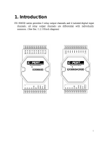
ExpertDAQ EX9018BL-M is an 8-channel thermocouple input module that offers accurate temperature measurement and monitoring capabilities. With its differential input type, it can measure temperatures in harsh industrial environments. The module supports various thermocouple types including J, K, T, E, R, S, B, and N. Its 16-bit resolution ensures precise temperature readings, and the configurable input range allows for flexible operation. Additionally, the EX9018BL-M features thermal couple break line detection, enabling users to quickly identify any issues with the thermocouple connection.

ExpertDAQ EX9018BL-M is an 8-channel thermocouple input module that offers accurate temperature measurement and monitoring capabilities. With its differential input type, it can measure temperatures in harsh industrial environments. The module supports various thermocouple types including J, K, T, E, R, S, B, and N. Its 16-bit resolution ensures precise temperature readings, and the configurable input range allows for flexible operation. Additionally, the EX9018BL-M features thermal couple break line detection, enabling users to quickly identify any issues with the thermocouple connection.

1
1. Introduction
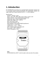
EX-9018/18-M/18BL/18BL-M/19/19-M is a thermocouple input
module and 8 input channels are differential type .
Specifications:
Interface: RS-485, 2 wires
Speed (bps): 1200, 2400, 4800, 9600, 19.2K, 38.4K, 15.2K
Analog Input type: Differential input
Analog Channels Numbers: 8
Analog Resolution: 16 bits
Unit Conversion: Thermocouple, mV, V or mA
Thermocouple Type: J, K, T, E, R, S, B, N
Sampling Rate :10 Samples/Second
Bandwidth : 15.7 Hz
Accuracy : ±0.1%
Zero Drift : 0.5μV/°C
Span Drift : 25ppm/°C
CMR@50/60Hz : 150dB
NMR@50/60Hz : 100dB
Input Impedance : 20M Ohms
Voltage Range: ±2.5V, ±1V,±500mV,±100mV,±50mV,±15mV
Current Measurement: ±20mA (with external 125 ohms resistor)
Power supply: +10V to +30V
Thermal couple break line detection (EX9018BL/BL-M/19/19-M
only)
2
Thermocouple Measurement
Two wires composed of dissimilar metal are joined at one end
and heated, the open circuit voltage is a function of the junction
temperature and the composition of the two metals. All dissimilar
metals exhibit this effect. The voltage is called "seebeck voltage".
For small changes in temperature the Seebeck Voltage is linearly
proportional to temperature.
For measure the Seebeck Voltage directly is not available
because we must connect a voltmeter to the thermocouple and the
voltmeter leads themselves create a new thermoelectric circuit
firstly. Therefore we need to eliminate the junction
thermoelectric to measure to correct Seebeck Voltage and this is
called "Cold Junction Compensation". For most thermocouples,
the Seebeck Voltage is 0V while in 0°C. The simple way to
cancel the junction voltage is to put the junction into 0°C
environment and the junction voltage is 0V. In general, this is not
a good method for most application. Typical method is to
measure the junction temperature by thermistor and measure the
junction voltage from the junction temperature that we may get
the Seebeck Voltage from measured thermocouple voltage and
junction voltage and we may calculate the temperature from the
Seebeck Voltage.
3
EX-9018/18-M/18BL/18BL-M/19/19-M
4
Specifications
EX-9018
EX-9018-M
EX-9018BL
EX-90018BL-M
EX-9019
EX-9019-M
Interface
RS-485, 2 wires
Speed(bps)
1200, 2400, 4800, 9600, 19200, 38400, 57600, 115200
Analog Input type
Differential input
Input Channels
8
Resolution
16 bits
Individual channel configuration
Not support
Support
Voltage Input
-15mV ~ +15mV
- 50mV ~ +50mV
- 100mV ~ +100mV
- 500mV ~ +500mV
- 1V ~ +1V
- 2.5V ~ +2.5V
Current Input
-20mA ~ +20mA (with 125ohms resistor)
Sensor Input
J, K, T, E, R, S, B, N
Sampling Rate
10 sample/second
Bandwidth
15.7Hz
Accuracy
±0.1%
Zero Drift
0.5μV/°C
Span Drift
25ppm/°C
CMR@50/60Hz
150dB
NMR@50/60Hz
100dB
Input Impedance
20M ohms
Power supply
+10V ~ +30V
Modbus RTU
EX9018-M
EX9018BL-M
EX9019-M
Thermal couple break line detect
Not support
Support
Notes:
1. Warm-UP for 30 minutes is recommended before starting operation!
2. EX-9018-M: EX-9018 w/ Modbus function
3. EX-9018BL: EX-9018 w/ Break Line function for Thermocouple
4. EX-9018BL-M: EX-9018BL w/ Modbus function
5. EX-9019: EX-9018BL w/ Individual Channel setting
6. EX-9019-M: EX-9019 w/ Modbus function
5
1.2 Wire connection
1.2.1 Block Diagrams:
EX-9018//18BL//19
6
1.2.2 Wiring diagram for the EX-9018/18BL/19
1.3 Default Settings
Default settings for the EX-9018/18BL/19 modules are as follows:
. Module Address: 01
. Analog Input Type: type 0F
. Baud Rate: 9600 bps
. Checksum disabled
. Engineering unit format
. Filter set at 60Hz rejection
Default settings for the EX-9018-M/18BL-M/19-M modules are as
follows:
. Protocol: Modbus RTU
. Module Address: 01
. Analog Input Type: type 0F
. Baud Rate: 9600 bps
. Filter set at 60Hz rejection
7
1.4 INIT* Mode Operation
Each EX9000 module has a build-in EEPROM to store configuration
information such as address, type, baudrate and other information.
Sometimes, user may forget the configuration of the module. Therefore,
the EX9000 have a special mode named "INIT* mode" to help user to
resolve the problem. The "INIT* mode" is setting as Address=00,
Budrate=9600bps, no Checksum .
Originally, the INIT* mode is accessed by connecting the INIT* terminal
to the GND terminal. New EX9000 modules have the INIT* switch
located on the rear side of the module to allow easier access to the INIT*
mode. For these modules, INIT* mode is accessed by sliding the INIT*
switch to the Init position as shown below.
To enable INIT* mode, please following these steps:
Step1. Power off the module
Step2. Connect the INIT* pin with the GND pin.
(or sliding the INIT* switch to the Init* ON position)
Step3. Power on
Step4. Send command $002 (cr) in 9600bps to read the
Configuration stored in the module's EEPROM.
There are commands that require the module to be in INIT* mode. They
are:
1. %AANNTTCCFF when changing the Baud Rate and checksum
settings. See Section 2.1 for details.
2. $AAPN, See Section 2.19 for details.
8
1.5 Module Status for DIO, AIO
Power On Reset or Module Watchdog Reset will let all output
goto Power On Value. And the module may accept the host's command
to change the output value.
Host Watchdog Timeout will let all output goto Safe Value. The
module's status(read by command~AA0) will be 04, and the output
command will be ignored.
1.6
Dual Watchdog Operation for DIO, AIO
Dual Watchdog=Module Watchdog + Host Watchdog
The Module Watchdog is a hardware reset circuit to monitor the
module's operating status. While working in harsh or noisy environment,
the module may be down by the external signal. The circuit may let the
module to work continues and never halt.
The Host Watchdog is a software function to monitor the host's
operating status. Its purpose is to prevent the network from
communication problem or host halt. When the timeout interval expired,
the module will turn all outputs to predefined Safe Value. This can
prevent the controlled target from unexpected situation.
The EX9000 module with Dual Watchdog may let the control
system more reliable and stable.
1.7 Reset Status
The Reset Status is set while the module power on or reset by module
watchdog and is cleared while the command read Reset Status ($AA5)
applied. This is useful for user to check the module's working status.
When the Reset Status is set means the module is reset and the output
may be changed to the PowerOn Value. When the Reset Status is clear
means the module is not resetted and the output is not changed.
9
1.8 Calibration(Warning: Please don't calibrate before you
really understand.)
Set the module of data format to which you wish to calibration first.
Protocol: ASCII mode.
Address: 01
Input type: which type you wish to calibration (If want calibrate the thermocouple type,
please set the type to -50~+50mV because use the same calibrate parameter)
Filter: which rejection you wish to calibration
Perform Zero Calibration:
1. Send the command $01501 to CH0 enable, CH1~7 disable.
2. Apply zero voltage/current to modules channel 0 (Vin0+ to Vin0-)
3. Send the command ~01E1 to enable calibration.
4. Send the command $011 to perform zero calibration.
Perform Span Calibration:
1. Send the command $01502 to CH1 enable, CH0 & 2~7 disable.
2. Apply Span voltage/current to modules channel 1
Type code
02
03
04
05
06
Span
+50mV
+100mV
+1V
+2.5V
+20mA
3. Send the command ~01E1 to enable calibration.
4. Send the command ~01CALS00550000 to perform span calibration.
5. Send the command #011 to check the CH0 input value is correct.
If the value is over the signal, decrease the value 550000.
If the value is less the signal, increase the value 550000.
The value should between 500000~5B0000, Hexadecimal format.
Note: While calibrate type of current, need connect external shunt resistor,
125ohms, 0.1% to channel1.
10
1.9 Configuration Tables
Baud Rate Setting (CC)
Code
03
04
05
06
07
08
09
0A
Baud rate
1200
2400
4800
9600
19200
38400
57600
115200
Sensor Type & V/I Range Setting (TT)
Code
Range
Format
+F.S.
Zero
-F.S.
00
-15~+15mV
Engineer unit
+15.000
+00.000
-15.000
% of F.S.R.
+100.00
+000.00
-100.00
2s complement
7FFF
0000
8000
01
-50~+50mV
Engineer unit
+50.000
+00.000
-50.000
% of F.S.R.
+100.00
+000.00
-100.00
2s complement
7FFF
0000
8000
02
-100~+100mV
Engineer unit
+100.00
+000.00
-100.00
% of F.S.R.
+100.00
+000.00
-100.00
2s complement
7FFF
0000
8000
03
-500~+500mV
Engineer unit
+500.00
+000.00
-500.00
% of F.S.R.
+100.00
+000.00
-100.00
2s complement
7FFF
0000
8000
04
-1~+1V
Engineer unit
+1.0000
+0.0000
-1.0000
% of F.S.R.
+100.00
+000.00
-100.00
2s complement
7FFF
0000
8000
05
-2.5~+2.5V
Engineer unit
+2.5000
+0.0000
-2.5000
% of F.S.R.
+100.00
+000.00
-100.00
2s complement
7FFF
0000
8000
06
-20~+20mA
Engineer unit
+20.000
+00.000
-20.000
% of F.S.R.
+100.00
+000.00
-100.00
2s complement
7FFF
0000
8000
0E
Type J T/C
-210~+760°C
Engineer unit
+760.00
+000.00
-210.00
% of F.S.R.
+100.00
+000.00
-027.63
2s complement
7FFF
0000
DCA2
0F
Type K T/C
-270~+1372°C
Engineer unit
+1372.0
+0000.0
-0270.0
% of F.S.R.
+100.00
+000.00
-019.68
2s complement
7FFF
0000
E6D0
10
Type T T/C
Engineer unit
+400.00
+000.00
-270.00
11
-270~+40C
% of F.S.R.
+100.00
+000.00
-067.50
2s complement
7FFF
0000
DCA2
11
Type E T/C
-270~+100C
Engineer unit
+1000.0
+000.00
-0270.0
% of F.S.R.
+100.00
+000.00
-027.00
2s complement
7FFF
0000
DD71
12
Type R T/C
0~+1768°C
Engineer unit
+1768.0
+0000.0
-0000.0
% of F.S.R.
+100.00
+000.00
-100.00
2s complement
7FFF
0000
0000
13
Type S T/C
0~+1768°C
Engineer unit
+1768.00
+0000.0
-0000.0
% of F.S.R.
+100.00
+000.00
-100.00
2s complement
7FFF
0000
0000
14
Type B T/C
0~+1820°C
Engineer unit
+1820.0
+0000.0
-0000.0
% of F.S.R.
+100.00
+000.00
-100.00
2s complement
7FFF
0000
0000
15
Type N T/C
-270~+130C
Engineer unit
+1300.0
+0000.0
-0270.0
% of F.S.R.
+100.00
+000.00
-020.77
2s complement
7FFF
0000
F54D
Data Format Setting (FF)
7
6
5
4
3
2
1
0
FS
CS
reserved
DF
Key
Description
DF
Data format
00: Engineering unit
01: % of FSR (full scale range)
10: 2‟s complement hexadecimal
CS
Checksum setting
0: Disabled
1: Enabled
FS
Filter setting
0: 60Hz rejection
1: 50Hz rejection
Note: The reserved bits should be zero.
Burnout (Break line for Thermocouple) statuss reading
Engineering Unit
+9999.9
% of FSR
+1315.7
2‟s Complement HEX
7FFF
12
2.0 Command set
2.1 %AANNTTCCFF
Description: Set Module Configuration.
Syntax: %AANNTTCCFF[CHK](cr)
%
a delimiter character
AA
address of setting/response module(00 to FF)
NN
new address for setting/response module(00 to FF)
TT
represents the type code. Type code determines the
input range.
If TT=FF the type of all channels keep no change.
CC
new baudrate for setting module.
FF
new data format for setting module.
IF the configuration with new baudrate or new checksum setting, before
using this command, the rear slide switch must be in the ON(INIT*)
position. The new setting is saved in the EEPROM and will be effective
after the next power-on reset.
Response: Valid Command: !AA
Invalid Command: ?AA
Example:
Command: %0203080602
Receive: !02
Set module address 02 to 03.
Input type code=08 (-10~+10V) for all channels
Baudrate=06 (9600)
Dataformat=02 (2s complement hexadecimal)
13
2.2 #AA
Description: Read Analog Input
Syntax: #AA[CHK](cr)
# delimiter character
AA address of reading/response module(00 to FF)
Response: Valid Command: >(Data)
(Data) analog input value for its format while use #AA command
to EX-9018BL/9019, the data is the combination for each
channel respectively.
Example :
Command: #04
Receive:>+051.23+041.53+072.34-023.56+100.00-
051.33+066.46+074.22
The module address 04 is EX-9018BL/9019. Read address 04 for
getting data of all 8 channels.
14
2.3 #AAN
Description : Read Analog Input from channel N
Syntax : #AAN[CHK](cr)
# delimiter character
AA address of reading/response module(00 to FF)
N channel to read, from 0 to 7
Response: Valid Command: >(Data)
Invalid Command: ?AA
(Data) analog input value for its format
Example :
Command : #032 Receive : >+025.13
Read address 03 channel 2, get data successfully.
Command : #029 Receive : ?02
Read address 02 channel 9, return error channel number.
15
2.4 ~AACALS00(Data)
Description: Perform Span Calibration
Syntax: $AA0[CHK](cr)
~ delimiter character
AA address of setting/response module (00 to FF)
CALS00 command for performing zero calibration
Data The init data is 55000
If the value(#AAN) is over the signal, decrease the value “550000”.
If the value(#AAN) is less the signal, increase the value “550000”.
The value should between 500000~5B0000, Hexadecimal format.
Response: Valid Command: !AA
Invalid Command: ?AA
Warning: Pls don't calibrate before you really understand.
16
2.5 $AA1
Description: Perform Zero Calibration
Syntax: $AA1[CHK](cr)
$ delimiter character
AA address of setting/response module (00 to FF)
1 command for performing zero calibration
Response: Valid Command: !AA
Invalid Command: ?AA
Example:
Command: $011 Receive: !01
Perform address 01 zero calibration on channel 0, return success.
Command: $021 Receive: ?02
Perform address 02 zero calibration on channel 2, return not
enable calibration before perform calibration command.
Warning: Pls don't calibrate before you really understand.
17
2.6 $AA2
Description: Read configuration.
Syntax: $AA2[CHK](cr)
$
delimiter character
AA
address of reading/response module (00 to FF)
2
command for read configuration
Response:
Valid Command:
!AATTCCFF
Invalid Command:
?AA
TT
type code of module
CC
baudrate code of module
FF
data format of module
Example:
Command: $012
Receive: !01400600
Read the configuration of module 01, input range of -2.5~+2.5V,
baudrate 9600, no checksum.
Note: check configuration Tables
18
2.7 $AA3
Description: Reads cold junction temperature.
Syntax: $AA3[CHK](cr)
$ delimiter character
AA address of reading/response module(00 to FF)
4 command to read cold junction temperature
Response: Valid Command: >(Data)
Invalid Command: ?AA
(Data) CJC temperature in degrees Celsius, consisting of a sign
byte, „+‟ or -and followed by 5 decimal digits with a
fixed decimal point in tenth of a degree
Example:
Command: $013 Receive: >+0030.2
Read address 01 cold junction temperature, and the module
responds with +0030.2
19
2.8 $AA5VV
Description: Set Channel Enable
Syntax: $AA5VV[CHK](cr)
$ delimiter character
AA address of setting/response module (00 to FF)
5 command for set channel enable
VV are two hexadecimal values. The values are interpreted by
the module as two binary words (4-bit). The first word
represents the status of channel 4~7, and the second word
represents the status of channel 0~3. Value 0 means the
channel is disabled, value 1 means the channel is enabled.
Response: Valid Command: !AA
Invalid Command: ?AA
Example:
Command :$0152A Receive : !01
Set address 01 to enable channel 1,3,5 and disable channel
0,2,4,6,7 return success.
Command : $016 Receive : !012A
Read address 01 channel status, return channel 1,3,5 are
enabled and channel 0,2,4,6,7 are disabled.
20
2.9 $AA6
Description: Read Channel Status
Syntax: $AA6[CHK](cr)
$ delimiter character
AA address of reading/response module (00 to FF)
6 command for read channel status
Response: Valid Command: !AAVV
Invalid Command: ?AA
VV are two hexadecimal values. The values are interpreted by
the module as two binary words (4-bit). The first word
represents the status of channel 4~7, and the second word
represents the status of channel 0~3. Value 0 means the
channel is disabled, value 1 means the channel is enabled.
Example:
Command :$0152A Receive : !01
Set address 01 to enable channel 1,3,5 and disable channel
0,2,4,6,7 return success.
Command : $016 Receive : !012A
Reads Read address 01 channel status, return channel 1,3,5 are
enabled and channel 0,2,4,6,7 are disabled.
  • Page 1 1
  • Page 2 2
  • Page 3 3
  • Page 4 4
  • Page 5 5
  • Page 6 6
  • Page 7 7
  • Page 8 8
  • Page 9 9
  • Page 10 10
  • Page 11 11
  • Page 12 12
  • Page 13 13
  • Page 14 14
  • Page 15 15
  • Page 16 16
  • Page 17 17
  • Page 18 18
  • Page 19 19
  • Page 20 20
  • Page 21 21
  • Page 22 22
  • Page 23 23
  • Page 24 24
  • Page 25 25
  • Page 26 26
  • Page 27 27
  • Page 28 28
  • Page 29 29
  • Page 30 30
  • Page 31 31
  • Page 32 32
  • Page 33 33
  • Page 34 34
  • Page 35 35
  • Page 36 36
  • Page 37 37
  • Page 38 38
  • Page 39 39
  • Page 40 40
  • Page 41 41
  • Page 42 42
  • Page 43 43
  • Page 44 44
  • Page 45 45
  • Page 46 46
  • Page 47 47
  • Page 48 48
  • Page 49 49
  • Page 50 50
  • Page 51 51

ExpertDAQ EX9018BL-M User manual

Type
User manual
This manual is also suitable for

ExpertDAQ EX9018BL-M is an 8-channel thermocouple input module that offers accurate temperature measurement and monitoring capabilities. With its differential input type, it can measure temperatures in harsh industrial environments. The module supports various thermocouple types including J, K, T, E, R, S, B, and N. Its 16-bit resolution ensures precise temperature readings, and the configurable input range allows for flexible operation. Additionally, the EX9018BL-M features thermal couple break line detection, enabling users to quickly identify any issues with the thermocouple connection.

Ask a question and I''ll find the answer in the document

Finding information in a document is now easier with AI