Page is loading ...

I-7017, I-7018, I-7019, M-7017,
M-7018 and M-7019 Series
User’s Manual
Warranty
All products manufactured by ICP DAS are under
warranty regarding defective materials for a period of one
year from the date of delivery to the original purchaser.
Warning
ICP DAS assumes no liability for damages resulting
from the use of this product. ICP DAS reserves the right
to change this manual at any time without notification.
The information furnished by ICP DAS is believed to be
accurate and reliable. However, no responsibility is
assumed by ICP DAS for its use, or for any infringements
of patents or other rights of third parties resulting from its
use.
Copyright
Copyright 1999 - 2009 ICP DAS. All rights reserved.
Trademark
The names used for identification only may be
registered trademarks of their respective companies.
Date: 2009/3/10
I-7017/18/19, M-7017/18/19 User’s Manual, Rev: B1.7 7MH-020-B17
1

Table of Contents
1. Introduction ...............................................................................................5
1.1 More Information ............................................................................. 8
1.2 Terminal Assignment .......................................................................9
1.3 Specifications .................................................................................16
1.4 Block Diagrams..............................................................................20
1.4.1 Block diagram for the I-7017, I-7017F, and M-7017 ..........20
1.4.2 Block diagram for the I-7017C, I-7017FC and M-7017C ...20
1.4.3 Block diagram for the I-7017R and M-7017R..................... 21
1.4.4 Block diagram for the I-7017R-A5 and M-7017R-A5 ....... 21
1.4.5 Block diagram for the I-7017Z and M-7017Z ..................... 22
1.4.6 Block diagram for the I-7018, I-7018P and M-7018 ..........22
1.4.7 Block diagram for the I-7018BL.......................................... 23
1.4.8 Block diagram for the I-7018R and M-7018R..................... 23
1.4.9 Block diagram for the I-7018Z and M-7018Z ..................... 24
1.4.10Block diagram for the I-7019R and M-7019R....................24
1.5 Dimensions.....................................................................................25
1.5.1 Modules without Frame Ground ..........................................25
1.5.2 Modules with Frame Ground ............................................... 26
1.6 Wiring Diagrams ............................................................................27
1.6.1 Wiring diagram for the I-7017, I-7017F, I-7017R, M-7017
and M-7017R
.........................................................................27
1.6.2 Wiring diagram for the I-7017C, I-7017FC, I-7017RC, M-
7017C and M-7017RC
..........................................................28
1.6.3 Wiring diagram for the I-7017R-A5 and M-7017R-A5......28
1.6.4 Wiring diagram for the I-7017Z and M-7017Z....................28
1.6.5 Wiring diagram for the I-7018, I-7018P, I-7018BL, I-7018R,
I-7018Z, M-7018, M-7018R and M-7018Z
..........................29
1.6.6 Wiring diagram for the I-7019R and M-7019R ...................30
1.7 Jumper Settings .............................................................................. 31
1.7.1 I-7017, I-7017F, I-7018, I-7018P and I-7018BL Jumper
Settings
..................................................................................31
1.7.2 I-7019R and M-7019R Jumper Settings...............................32
1.8 Quick Start...................................................................................... 34
1.9 Default Settings ..............................................................................36
1.10 Calibration .................................................................................... 38
1.11 Configuration Tables....................................................................41
1.12 M-7000 Notes...............................................................................48
1.12.1 Protocol Switching ............................................................. 48
1.12.2 INIT Mode..........................................................................49
1.13 Mounting ......................................................................................50
I-7017/18/19, M-7017/18/19 User’s Manual, Rev: B1.7 7MH-020-B17
2

1.13.1 DIN Rail Mounting ............................................................50
1.13.2 Piggyback Mounting ..........................................................52
1.13.3 Wall Mounting....................................................................53
1.14 Technical Support.........................................................................54
2. DCON Protocol.......................................................................................55
2.1 %AANNTTCCFF ..........................................................................59
2.2 #** ..................................................................................................63
2.3 #AA ................................................................................................65
2.4 #AAN, #AANN..............................................................................67
2.5 $AA0 ..............................................................................................69
2.6 $AA1 ..............................................................................................71
2.7 $AA0Ci...........................................................................................73
2.8 $AA1Ci...........................................................................................75
2.9 $AA2 ..............................................................................................77
2.10 $AA3 ............................................................................................ 79
2.11 $AA4 ............................................................................................ 81
2.12 $AA5VV, $AA5VVVV ...............................................................83
2.13 $AA6 ............................................................................................ 85
2.14 $AA7CiRrr ................................................................................... 87
2.15 $AA8Ci ........................................................................................89
2.16 $AA9 ............................................................................................ 91
2.17 $AA9SNNNN ..............................................................................93
2.18 $AAA ...........................................................................................95
2.19 $AAA ...........................................................................................97
2.20 $AAAi .......................................................................................... 99
2.21 $AAB..........................................................................................101
2.22 $AAF ..........................................................................................103
2.23 $AAM.........................................................................................104
2.24 $AAP ..........................................................................................106
2.25 $AAPN .......................................................................................108
2.26 $AAS0 ........................................................................................ 110
2.27 $AAS1 ........................................................................................ 112
2.28 ~AAC .........................................................................................114
2.29 ~AACN....................................................................................... 116
2.30 ~AAEV.......................................................................................118
2.31 ~AAI........................................................................................... 120
2.32 ~AAO(Name).............................................................................122
2.33 ~AATnn......................................................................................124
2.34 ~**.............................................................................................. 127
2.35 ~AA0 .......................................................................................... 128
2.36 ~AA1 .......................................................................................... 130
2.37 ~AA2 .......................................................................................... 132
2.38 ~AA3EVV..................................................................................134
I-7017/18/19, M-7017/18/19 User’s Manual, Rev: B1.7 7MH-020-B17
3

2.39 @AAS ........................................................................................136
2.40 @AASN .....................................................................................138
3. Modbus RTU Protocol ..........................................................................140
3.1 02 (0x02) Read Input Status.........................................................141
3.2 04 (0x04) Read Input Channels.................................................... 142
3.3 70 (0x46) Read/Write Module Settings .......................................143
3.3.1 Sub-function 00 (0x00) Read module name ...................... 144
3.3.2 Sub-function 04 (0x04) Set module address ...................... 145
3.3.3 Sub-function 05 (0x05) Read communication settings......146
3.3.4 Sub-function 06 (0x06) Set communication settings.........147
3.3.5 Sub-function 07 (0x07) Read type code.............................148
3.3.6 Sub-function 08 (0x08) Set type code................................149
3.3.7 Sub-function 32 (0x20) Read firmware version.................150
3.3.8 Sub-function 37 (0x25) Read channel enabled/disabled status
.............................................................................................151
3.3.9 Sub-function 38 (0x26) Set channel enable/disable...........152
3.3.10 Sub-function 41 (0x29) Read miscellaneous settings ......153
3.3.11 Sub-function 42 (0x2A) Write miscellaneous settings .... 154
3.3.12 Sub-function 43 (0x2B) Read CJC offset ........................155
3.3.13 Sub-function 44 (0x2C) Write CJC offset .......................156
3.3.14 Sub-function 45 (0x2D) Read CJC enabled/disabled status
.............................................................................................157
3.3.15 Sub-function 46 (0x2E) Set CJC enable/disable..............158
3.3.16 Sub-function 47 (0x2F) Read CJC update setting............ 159
3.3.17 Sub-function 48 (0x30) Write CJC update setting........... 160
3.4 Address Mappings........................................................................ 161
3.4.1 M-7017 Series Address Mappings ..................................... 161
3.4.2 M-7017Z Address Mappings .............................................163
3.4.3 M-7018 Series Address Mappings ..................................... 165
3.4.4 M-7018Z Address Mappings .............................................167
3.4.5 M-7019R Address Mappings .............................................169
3.5 Engineering Data Format Table ...................................................171
4. Troubleshooting ....................................................................................173
4.1 Communicating with the module ................................................. 174
4.2 Reading Data ................................................................................ 175
A. Appendix .............................................................................................. 176
A.1 INIT Mode...................................................................................176
A.2 Dual Watchdog Operation...........................................................178
A.3 Thermocouple..............................................................................179
A.4 Frame Ground.............................................................................. 180
A.5 Node Information Area ...............................................................182
I-7017/18/19, M-7017/18/19 User’s Manual, Rev: B1.7 7MH-020-B17
4

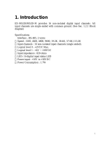
1. Introduction
The I-7000 series is a family of network data acquisition
and control modules, providing analog-to-digital, digital-
to-analog, digital input/output, timer/counter and other
functions. The modules can be remotely controlled using
a set of commands, which we call the DCON protocol.
Communication between the module and the host is in
ASCII format via an RS-485 bi-directional serial bus
standard. Baud Rates are software programmable and
transmission speeds of up to 115.2K baud can be selected.
The functionality of the M-7000 series is the same as the
I-7000 series, with the exception that the M-7000 series
offers extended support for the Modbus RTU protocol.
Some I-7000 and all M-7000
modules feature a new design
for the frame ground and INIT
switch as shown in the figure
(rear view). The frame ground
provides enhanced static
protection (ESD) abilities and
ensures the module is more
reliable. The INIT switch
allows INIT mode to be
accessed more easily. Refer to
Sections A.1 and A.4 for more
details.
The common features of the I-7017, I-7018 and I-7019 are
as follows:
1. 3000V DC inter-module isolation
I-7017/18/19, M-7017/18/19 User’s Manual, Rev: B1.7 7MH-020-B17
5

2. 24-bit sigma-delta ADC to provide excellent accuracy
3. Software calibration
The I-7017 is an 8-channel voltage and current input
module. The I-7018 is an 8-channel voltage, current and
thermocouple input module. The I-7019 is an 8-channel
voltage, current, and thermocouple input module, with the
ability to connect various types of inputs to a single
module.
The I-7017 has the following variations:
I-7017F: added support for fast mode, 60
samples/second.
I-7017C: used for current input only, with no external
resistor required.
I-7017FC: used for current input only, with no external
resistor required. Added support for fast mode, 60
samples/second.
I-7017R: added high voltage overload protection,
240Vrms.
I-7017RC: used for current input only, with no external
resistor required. Added high voltage overload
protection, 240Vrms.
I-7017R-A5: used for high voltage input
I-7017Z: 10 channels, added high voltage overload
protection, 240Vrms
The I-7018 has the following variations:
I-7018P: added support for two additional
thermocouple types, L and M
I-7018BL: added thermocouple wire opening detection
I-7018R: added thermocouple wire opening detection
and high voltage overload protection, 240Vrms
I-7017/18/19, M-7017/18/19 User’s Manual, Rev: B1.7 7MH-020-B17
6

I-7018Z: 10 channels, added thermocouple wire
opening detection and high voltage overload protection,
240Vrms
The I-7019 has the following variation:
I-7019R: added high voltage overload protection,
240Vrms
The I-7017R, I-7017RC, I-7017Z, I-7018R, I-7018Z and
I-7019R modules are designed for industrial plant
environments and have special input circuits to provide
240Vrms continuous overload protection as shown in the
figure.
I-7017/18/19, M-7017/18/19 User’s Manual, Rev: B1.7 7MH-020-B17
7

1.1 More Information
Refer to chapter 1 of the “I-7000 Bus Converter User’s
Manual” as shown below or visit the ICP DAS website
http://www.icpdas.com for more information regarding the
I-7000 series.
1.1 The I-7000 Series Overview
1.2 Related Documentation for the I-7000 Series
1.3 Common Features of the I-7000 Series
1.4 The I-7000 Series System Network Configuration
1.5 I-7000 Dimensions
I-7017/18/19, M-7017/18/19 User’s Manual, Rev: B1.7 7MH-020-B17
8

1.2 Terminal Assignment
I-7017/18/19, M-7017/18/19 User’s Manual, Rev: B1.7 7MH-020-B17
9

I-7017/18/19, M-7017/18/19 User’s Manual, Rev: B1.7 7MH-020-B17
10

I-7017/18/19, M-7017/18/19 User’s Manual, Rev: B1.7 7MH-020-B17
11

I-7017/18/19, M-7017/18/19 User’s Manual, Rev: B1.7 7MH-020-B17
12

I-7017/18/19, M-7017/18/19 User’s Manual, Rev: B1.7 7MH-020-B17
13

I-7017/18/19, M-7017/18/19 User’s Manual, Rev: B1.7 7MH-020-B17
14

I-7017/18/19, M-7017/18/19 User’s Manual, Rev: B1.7 7MH-020-B17
15

1.3 Specifications
I-7017/M-7017 I-7017F/I-7017R
M-7017R
I-7017C
*3
/I-7017FC/I-7017RC
M-7017C
*3
/M-7017RC
Analog Input
Input Channels 8 differential
*1
8 differential
*1
8 differential
Input Type mV, V, mA
*2
mV, V, mA
*2
mA
Sampling Rate 10 samples/sec
10 samples/sec (normal)
60 samples/sec (fast)
10 samples/sec (normal)
60 samples/sec (fast)
Bandwidth 15.7Hz 15.7Hz (normal)
78.7Hz (fast)
15.7Hz (normal)
78.7Hz (fast)
Accuracy ±0.1% ±0.1% (normal)
±0.5% (fast)
±0.1% (normal)
±0.5% (fast)
Zero Drift 20µV/°C 20µV/°C 20µV/°C
Span Drift 25ppm/°C 25ppm/°C 25ppm/°C
CMR@50/60Hz 86dB min 86dB min 86dB min
NMR@50/60Hz 100dB min 100dB min 100dB min
Input Impedance 20MΩ I-7017R/M-7017R
1MΩ
I-7017F
20MΩ
125Ω
Voltage
overload
Protection
±35V I-7017R/M-7017R
±240V
I-7017F
±35V
I-7017RC/M-7017RC
±240V
I-7017C/FC/M-7017C
±35V
Isolation 3000V DC 3000V DC 3000V DC
Modbus RTU M-7017 M-7017R M-7017C/M-7017RC
Power
Requirement +10 to +30V DC +10 to +30V DC +10 to +30V DC
Consumption 1.3W 1.3W 1.3W
Temperature
Range
Operating -25°C to +75°C -25°C to +75°C -25°C to +75°C
Storage -30°C to +75°C -30°C to +75°C -30°C to +75°C
*1: For I-7017 and I-7017F, the number of input channels is 8 differential or 6
differential and 2 single-ended by jumper selection.
*2: requires optional external 125 ohm resistor.
*3: I-7017C and M-7017C does not support fast mode, 60 samples/sec sampling rate.
Note: A warm up period of 30 minutes is recommended in order to achieve the complete
performance results described in the specifications.
I-7017/18/19, M-7017/18/19 User’s Manual, Rev: B1.7 7MH-020-B17
16

I-7017R-A5
M-7017R-A5
I-7017Z
M-7017Z
Analog Input
Input Channels 8 differential 10 differential/20 single-
ended
Input Type V mV, V, mA (jumper
selectable)
Sampling Rate 10 samples/sec (normal)
50 samples/sec (fast)
10 samples/sec (normal)
60 samples/sec (fast)
Bandwidth 15.7Hz (normal)
78.7Hz (fast)
15.7Hz (normal)
78.7Hz (fast)
Accuracy ±0.1% (normal)
±0.25% (fast)
±0.1% (normal)
±0.5% (fast)
Zero Drift 20µV/°C 20µV/°C
Span Drift 25ppm/°C 25ppm/°C
CMR@50/60Hz 86dB min 86dB min
NMR@50/60Hz 100dB min 100dB min
Input Impedance 290KΩ Differential: 2MΩ
Single-ended: 1MΩ
Current
Impedance
125Ω, 1/4W
Voltage overload
Protection
±200V Differential: ±240V
Single-ended: ±150V
Isolation 3000V DC 3000V DC
Individual
Channel
Configurable
No Yes
Modbus RTU M-7017R-A5 M-7017Z
Power
Requirement +10 to +30V DC +10 to +30V DC
Consumption 1.7W 2.0W
Temperature
Range
Operating -25°C to +75°C -25°C to +75°C
Storage -30°C to +75°C -30°C to +75°C
Note: A warm up period of 30 minutes is recommended in order to
achieve the complete performance results described in the
specifications.
I-7017/18/19, M-7017/18/19 User’s Manual, Rev: B1.7 7MH-020-B17
17

I-7018
M-7018
I-7018P/I-7018Z
M-7018Z
I-7018BL/I-7018R
M-7018R
Analog Input
Input Channels 8 differential
*1
8 diff
*1
(10 for 7018Z) 8 differential
*1
Input Type mV, V, mA
*2
mV, V, mA
*2
mV, V, mA
*2
Thermocouple
Type
J, K, T, E, R, S, B, N,
C
J, K, T, E, R, S, B, N,
C, L, M
J, K, T, E, R, S, B, N, C
Sampling Rate 10 samples/sec 10 samples/sec 10 samples/sec
Bandwidth 15.7Hz 15.7Hz 15.7Hz
Accuracy ±0.1% ±0.1% I-7018R/M-7018R
±0.2%
I-7018BL
±0.1%
Zero Drift 0.5µV/°C 0.5µV/°C 10µV/°C
Span Drift 25ppm/°C 25ppm/°C 25ppm/°C
CMR@50/60Hz 150dB min 150dB min 86dB min
NMR@50/60Hz 100dB min 100dB min 100dB min
Input Impedance 20MΩ 20MΩ I-7018R/M-7018R
1MΩ
I-7018BL
20MΩ
Voltage
overload
Protection
±35V I-7018Z/M-7018Z
±240V
I-7018P
±35V
I-7018R/M-7018R
±240V
I-7018BL
±35V
Isolation 3000V DC 3000V DC 3000V DC
Open Wire
Detection
No Yes for I-7018Z/
M-7018Z
Yes
Modbus RTU M-7018 M-7018Z M-7018R
Power
Requirement +10 to +30V DC +10 to +30V DC +10 to +30V DC
Consumption 1.0W 1.0W 1.0W
Temperature Range
Operating -25°C to +75°C -25°C to +75°C -25°C to +75°C
Storage -30°C to +75°C -30°C to +75°C -30°C to +75°C
*1: For I-7018, I-7018P and I-7018BL, the number of input channels is 8 differential or 6
differential and 2 single-ended by jumper selection.
*2: requires optional external 125 ohm resistor
*3: I-7018Z and M-7018Z are individual channel configurable.
Note: A warm up period of 30 minutes is recommended in order to achieve the
complete performance results described in the specifications.
I-7017/18/19, M-7017/18/19 User’s Manual, Rev: B1.7 7MH-020-B17
18

I-7019R/M-7019R
Analog Input
Input Channels 8 differential
Input Type mV, V, mA (jumper selectable)
Thermocouple Type J, K, T, E, R, S, B, N, C, L, M, LDIN43710
Sampling Rate 8 samples/sec
Bandwidth 5.24Hz
Accuracy ±0.15%
Zero Drift 10µV/°C
Span Drift 25ppm/°C
CMR@50/60Hz 86dB min
Input Impedance 2MΩ
Current Impedance 125Ω, 1/4W
Voltage overload
Protection
±240V
Isolation 3000V DC
Open Wire Detection Yes
Individual Channel
Configurable
Yes
Modbus RTU M-7019R
Power
Requirement +10 to +30V DC
Consumption 1.2W
Temperature Range
Operating -25°C to +75°C
Storage -30°C to +75°C
Note: A warm up period of 30 minutes is recommended in order to
achieve the complete performance results described in the
specifications.
I-7017/18/19, M-7017/18/19 User’s Manual, Rev: B1.7 7MH-020-B17
19

1.4 Block Diagrams
1.4.1 Block diagram for the I-7017, I-7017F, and
M-7017
1.4.2 Block diagram for the I-7017C, I-7017FC and
M-7017C
I-7017/18/19, M-7017/18/19 User’s Manual, Rev: B1.7 7MH-020-B17
20
/