Page is loading ...

#8311 • 4/06
W164 N9221 Water Street • P.O. Box 450 • Menomonee Falls, Wisconsin 53052-0450 USA
PHONE: 262.251.3800 • 800.558.8744 USA/CANADA FAX: 262.251.7067 • 800.329.8744 U.S.A. ONLY
WEBSITE: www.alto-shaam.com
PRINTED IN U.S .A .
®
Cooking & Holding Oven
Electronic Control
Models:
500-TH-III
750-TH-III
1000-TH-III
1200-TH-III
• INSTALLATION
• OPERATION
• MAINTENANCE
1200-TH/III
1000-TH/III
750-TH/III
500-TH/III


#8311 INSTALLATION/OPERATION/SERVICE MANUAL PG. 1
DELIVERY
This Alto-Shaam appliance has been
thoroughly tested and inspected to insure only the
highest quality unit is provided. Upon receipt,
check for any possible shipping damage and
report it at once to the delivering carrier. See
Transportation Damage and Claims section
located in this manual.
This appliance, complete with unattached
items and accessories, may have been delivered in
one or more packages. Check to ensure that all
standard items and options have been received
with each model as ordered.
Save all the information and instructions
packed with the appliance. Complete and return
the warranty card to the factory as soon as
possible to assure prompt service in the event of a
warranty parts and labor claim.
This manual must be read and understood by
all people using or installing the equipment
model. Contact the Alto-Shaam service
department if you have any questions concerning
installation, operation, or maintenance.
NOTE: All claims for warranty must include the
full model number and serial number of
the unit.
UNPACKING
1. Carefully remove the
appliance from the
carton or crate.
NOTE: Do not discard the
carton and other
packaging material
until you have
inspected the unit
for hidden damage
and tested it for
proper operation.
2. Read all instructions in this manual carefully
before initiating the installation of this appliance.
DO NOT DISCARD THIS MANUAL.
This manual is considered to be part of the
appliance and is to be provided to the owner
or manager of the business or to the person
responsible for training operators. Additional
manuals are available from the Alto-Shaam
service department.
3. Remove all protective plastic film, packaging
materials, and accessories from the appliance
before connecting electrical power. Store any
accessories in a convenient place for future use.
®
®
®

PG. 2 #8311 INSTALLATION/OPERATION/SERVICE MANUAL
SAFETY PROCEDURES
AND PRECAUTIONS
Knowledge of proper procedures is essential to the
safe operation of electrically and/or gas energized
equipment. In accordance with generally accepted
product safety labeling guidelines for potential
hazards, the following signal words and symbols
may be used throughout this manual.
Used to indicate the
presence of a hazard that
will cause severe personal
injury, death, or substantial
property damage if the
warning included with this
symbol is ignored.
Used to indicate the
presence of a hazard that
can
cause personal injury,
possible death, or major
property damage if the
warning included with this
symbol is ignored.
Used to indicate the
presence of a hazard that
can or will cause minor or
moderate personal injury
or property damage if the
warning included with this
symbol is ignored.
Used to indicate the
presence of a hazard that
can or will cause minor
personal injury, property
damage, or a potential
unsafe practice if the
warning included with this
symbol is ignored.
Used to notify personnel of
installation, operation, or
maintenance information that is
important but not hazard related.
1. This appliance is intended to cook, hold or
process foods for the purpose of human
consumption. No other use for this
appliance is authorized or recommended.
2. This appliance is intended for use in
commercial establishments where all
operators are familiar with the purpose,
limitations, and associated hazards of this
appliance. Operating instructions and
warnings must be read and understood by
all operators and users.
3. Any troubleshooting guides, component
views, and parts lists included in this manual
are for general reference only and are intended
for use by qualified technical personnel.
4. This manual should be considered a
permanent part of this appliance. This
manual and all supplied instructions,
diagrams, schematics, parts lists, notices, and
labels must remain with the appliance if the
item is sold or moved to another location.
NOTE:

#8311 INSTALLATION/OPERATION/SERVICE MANUAL PG. 3
SITE INSTALLATION
The Alto-Shaam cook
and hold oven must
be installed in a
location that will
permit the oven to
function for its
intended purpose and
to allow adequate
clearance for
ventilation, proper
cleaning, and
maintenance access.
1. The oven must be installed on a stable and
level surface.
2. DO NOT install this appliance in any area
where it may be affected by any adverse
conditions such as steam, grease, dripping
water, high temperatures, or any other severely
adverse conditions.
3. DO NOT store or use any flammable liquids or
allow flammable vapors in the vicinity of this
oven or any other appliance.
4. This appliance must be kept free and clear of
any combustible materials.
5. This appliance must be kept free and clear of
any obstructions blocking access for
maintenance or service.
®
TO PREVENT PERSONAL INJURY,
USE CAUTION WHEN MOVING OR
LEVELING THIS APPLIANCE.
METAL PARTS OF THIS EQUIPMENT
BECOME EXTREMELY HOT WHEN IN
OPERATION. TO AVOID BURNS,
ALWAYS USE HAND PROTECTION
WHEN OPERATING THIS APPLIANCE.
DO NOT store or use any flammable
liquids or allow flammable vapors
in the vicinity of any appliance.
IMPROPER INSTALLATION, ALTERATION,
ADJUSTMENT, SERVICE OR MAINTENANCE
COULD RESULT IN SEVERE INJURY, DEATH
OR CAUSE PROPERTY DAMAGE.
INSTALLATION
Emissions testing conducted by Underwriters
Laboratories, Inc.® was found to be in
compliance with the applicable requirements of
NFPA96: 2004 Edition, Par. 4.1.1.2. U.L
emissions sampling of grease laden vapor
resulted in a total of 0.55 milligrams per cubic
meter with no visible smoke and is considered
representative of all oven models in the line.
Based on these results, hood installation and/or
outside venting should not be a requirement in
most areas. Verify local codes for locations
where more restrictive codes are applicable.
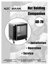
MINIMUM CLEARANCE REQUIREMENTS
18" (457mm) minimum clearance at back from heat
producing equipment.

PG. 4 #8311 INSTALLATION/OPERATION/SERVICE MANUAL
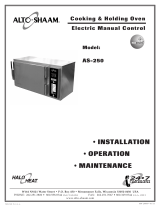
SITE INSTALLATION
INSTALLATION
with #4007 casters or #5205 legs
33-3/16" (843mm)
31-3/4" (806mm)
54-1/4" (1378mm)
55-3/4" (1417mm)
Detachable
Cord exits
5-13/16" (147mm)
from top
11-1/16" (281mm)
Optional Full
Perimeter Bumper
®
25-7/16" (645mm)
27-7/8" (708mm)
with optional bumper
29-3/8" (746mm)
28-3/16" (717mm)
35-1/8" (892mm)
35-3/4" (908mm)
22-9/32" (566mm)
25-1/4" (642mm)
with optional bumper
42" (1067mm)
with #4007 casters or #5205 legs
52-11/16" (1338mm)
51-3/16" (1300mm)
32-1/2" (826mm)
33-3/16" (843mm)
Electrical
Connection
5-13/16" (147mm)
from top
Optional Full
Perimeter Bumper
11-1/16" (281mm)
35-1/8" (892mm)
28-7/8" (734mm)
17-1/2" (445mm)
42-1/2" (1078mm)
27-5/8" (701mm)
26-5/8" (677mm)
19-1/4" (489mm)
HANDLE TIP
RACK
WITH 5"
CASTERS
Electrical Connection 3-5/8" (92mm) from top
9" (232mm)
32-5/8" (829mm)
53-3/16" (1350mm)
22-1/8" (562mm)
25-7/16" (646mm)
11-1/16"
(281mm)
33-9/16" (852mm)
Electrical
Connection
6-9/16" (167mm)
from top
REACH IN
67-1/16" (1703mm)
74" (1879mm)
C
L
WEIGHT
MODEL NET SHIP
500-TH/III 150 lb (68 kg) 165 lb (75 kg)
500-TH/III/D 160 lb (73 kg) 175 lb (79 kg)
750-TH/III 218 lb (99 kg) 244 lb (111 kg)
750-TH/III/D 224 lb (102 kg) 250 lb (113 kg)
1000-TH/III 230 lb (104 kg) 238 lb (108 kg)
1000-TH/III/D 237 lb (108 kg) 245 lb (111 kg)
1200-TH/III 420 lb (191 kg) 475 lb (215 kg)
1200-TH/III/D 425 lb (193 kg) 490 lb (222 kg)
1200-TH/III/PT 440 lb (200 kg) 500 lb (227 kg)
1200-TH/III/D/PT 455 lb (206 kg) 515 lb (234 kg)
13" (330mm)
73-3/8" (1863mm)
Electrical
Connection
2-7/32" (56mm)
from top
500-TH-III
40 lb (18 kg) max.
Capacity
750-TH-III
100 lb (45 kg) max.
Capacity
1000-TH-III
120 lb (54 kg) max.
Capacity
1200-TH-III
120 lb (54 kg) max.
Capacity per Compartment
1200-TH-III/PT
PASS THRU

#8311 INSTALLATION/OPERATION/SERVICE MANUAL PG. 5
SITE INSTALLATION
INSTALLATION
A number of adjustments are associated with
initial installation and start-up. It is important
that these adjustments be conducted by a qualified
service technician. Installation and start-up
adjustments are the responsibility of the dealer or
user. These adjustments include but are not
limited to thermostat calibration, door adjustment,
leveling, electrical hook-up and installation of
optional casters or legs.
LEVELING
Level the oven
from side-to-side and back-to-
back with the use of a spirit level. For ovens
installed with casters, it is important that the
installation surface be level due to the probability
of frequent oven repositioning.
We recommend checking the level of the oven
periodically to make certain the floor has not
shifted nor the oven moved.
NOTE: Failure to properly level this oven can
cause improper function and will result in
the uneven baking with products
consisting of semi-liquid batter.
RESTRAINT REQUIREMENTS
—MOBILE EQUIPMENT
Any appliance that is not furnished with a power
supply cord but that includes a set of casters must
be installed with a tether. Adequate means must
be provided to limit the movement of this
appliance without depending on or transmitting
stress to the electrical conduit. The following
requirements apply:
1. Casters must be a maximum height of 6" (152mm).
2. Two of the casters must of be the locking type.
3. Such mobile appliances or appliances on mobile
stands must be installed with the use of a flexible
connector secured to the building structure.
A mounting connector for a restraining device is
located on the lower back flange of the appliance
chassis or on an oven stand, approximately 18"
(457mm) from the floor. A flexible connector is not
supplied by nor is it available from the factory.
RISK OF ELECTRIC SHOCK.
Appliance must be secured
to building structure.

PG. 6 #8311 INSTALLATION/OPERATION/SERVICE MANUAL
WHEN MOUNTING
DRIP STRIP, SEAL
STRIP TO THE UNIT
WITH AN R.T.V.
SEALANT TO PREVENT
MOISTURE FROM
PENETRATING INTO
OVEN COMPARTMENT
DRIP
STRIP*
3: #8-32 X 1/2" SCREWS*
*SEE ALTO-SHAAM PARTS LIST FOR ALTO-SHAAM PART NUMBERS.
STANDARD DRIP PAN*
[BOTTOM OF OVEN INTERIOR •
BELOW SIDE-RACKS]
DRIP
TRAY*
DRIP TRAY INSTALLATION INSTRUCTIONS
LOW TEMPERATURE TH/III SERIES
COOKING & HOLDING OVENS
FAILURE TO PROPERLY INSTALL
THE DRIP TRAY CAN OR WILL
CAUSE MAJOR EQUIPMENT
DAMAGE AND WILL RESULT IN A
LEAKAGE HAZARD THAT CAN
CAUSE PERSONAL INJURY.
SITE INSTALLATION
INSTALLATION

#8311 INSTALLATION/OPERATION/SERVICE MANUAL PG. 7
The appliance must be installed by a qualified
service technician. The oven must be properly
grounded in accordance with the National
Electrical Code and applicable local codes.
Plug the unit into a properly grounded receptacle
ONLY, positioning the unit so that the plug is
easily accessible in case of an emergency. Arcing
will occur when connecting or disconnecting the
unit unless all controls are in the “OFF” position.
Proper receptacle or outlet configuration or
permanent wiring for this unit must be installed
by a licensed electrician in accordance with
applicable local electrical codes.
ELECTRICAL CONNECTION
INSTALLATION
To avoid electrical shock, this
appliance MUST be adequately
grounded in accordance with local
electrical codes or, in the absence of
local codes, with the current edition
of the National Electrical Code
ANSI/NFPA No. 70. In Canada, all
electrical connections are to be made
in accordance with CSA C22.1,
Canadian Electrical Code Part 1 or
local codes.
ELECTRICAL CONNECTIONS MUST
BE MADE BY A QUALIFIED SERVICE
TECHNICIAN IN ACCORDANCE WITH
APPLICABLE ELECTRICAL CODES.
ELECTRICAL
VOLTAGE PHASE CYCLE/HZ AMPS kW
at 120 1 50/60 15.0 1.80
at 208 1 50/60 10.5 2.1
at 240 1 50/60 11.5 2.7
at 230 1 50/60 11.0 2.5
at 208 1 50/60 14.0 2.9
at 240 1 50/60 16.0 3.8
at 230 1 50/60 15.5 3.6
at 208 1 50/60 26.0 5.4
at 240 1 50/60 30.0 7.2
at 230 1 50/60 28.7 6.6
500-TH-III
750-TH-III
1000-TH-III
1200-TH/III

PG. 8 #8311 INSTALLATION/OPERATION/SERVICE MANUAL
No. 16222 or 16237 Kit
Using Stacking Platform from
Kit #16222 or 16237
to provide carving shelf:
1. Remove the three screws in the top plate at the front of
the cabinet.
2. Remove the three screws in the back plate near the top
of the cabinet.
3. Position the stacking platform on top of the unit with
the flange in front, aligning the holes in the platform
over the holes in the cabinet.
4. Reinstall the cabinet screws removed in steps 1 and 2
through the platform holes to attach it to the cabinet,
front and back.
5. Place the carvery shelf on the stacking platform.
for stacking carving shelf
Step 1
Step 2
Stacking Configurations
Configuration Stacking Assembly
1000-TH/III OVER 1000-TH/III • 1000-TH/III OVER 1000-S
750-TH/III
OVER 750-TH/III • 750-TH/III OVER 767-SK/III 5000811
500-TH/III
OVER 500-TH/III • 500-TH/III OVER 500-S
1000-S
OVER 100-TH/III
750-TH/III
OVER OR UNDER 750-S 5001359
500-S
OVER 500-TH/III
TM
OVER 500-S or 500-TH/III 16237
BCS
OVER 750-S or 750-TH/III 16222
or 750-TH/III
500-TH/III
STACKING MOUNTING INSTRUCTIONS
INSTALLATION

#8311 INSTALLATION/OPERATION/SERVICE MANUAL PG. 9
Depth
Width
Stacking
Plate
Steps 3 and 4
above
STACKING PLATE INSTALLATION
Kit #5000811
1. Measure the length and width of the top surface of the
cabinet to be positioned at the bottom of the stacking
equipment combination. Add 1/8-inch to both the
length and the width dimension.
2. Turn the cabinet to be placed at the top of the stacking
combination upside down so that the top surface is on
the floor.
3. Place the four (4) stacking plates at each corner of the
cabinet. Position the plates with the upright flange
pointing up and to the outside of the cabinet. Align
the holes in the stacking plates with the predrilled
holes in the bottom of the cabinet using both the length
and width dimensions obtained in step 1.
4. When the correct alignment has been achieved, loosely
fasten each stacking plate with four (4) screws
provided in the stacking kit. DO NOT TIGHTEN
SECURELY since minor adjustments may be necessary.
5. Stack the cabinets and make any necessary minor
adjustments to the stacking plates. When properly
aligned, the door on the top cabinet should be flush
with the door on the bottom cabinet.
6. When proper alignment has been made, remove the
top cabinet from the stacking combination. Firmly
secure all four stacking plates by individually
removing each screw and reattaching it in combination
with one of the square washers provided in the
stacking kit.
STACKING MOUNTING INSTRUCTIONS
INSTALLATION

PG. 10 #8311 INSTALLATION/OPERATION/SERVICE MANUAL
STACKING PLATE INSTALLATION
Kit #5001359
1. Measure the length and width of the top surface of
the cabinet to be positioned at the bottom of the
stacking equipment combination. Add 1/8-inch to
both the length and the width dimension.
2. Turn the cabinet to be placed at the top of the
stacking combination upside down so that the top
surface is on the floor. Remove the eight (8) bolts
located at the front (door side) and at the rear of the
cabinet. Replace the bolts with the eight (8) nylon
plugs provided in the stacking kit (RI-26196).
3. Place the four (4) stacking plates at each corner of
the cabinet. Position the plates with the upright
flange pointing up and to the outside of the cabinet.
Align the holes in the stacking plates with the
predrilled holes in the bottom of the cabinet using
both the length and width dimensions obtained in
step 1.
4. When the correct alignment has been achieved,
loosely fasten each stacking plate with four (4)
screws provided in the stacking kit. DO NOT
TIGHTEN SECURELY since minor adjustments may
be necessary.
5. Stack the cabinets and make any necessary minor
adjustments to the stacking plates. When properly
aligned, the door on the top cabinet should be flush
with the door on the bottom cabinet.
6. When proper alignment has been made, remove the
top cabinet from the stacking combination. Firmly
secure all four stacking plates by individually
removing each screw and reattaching it in
combination with one of the square washers
provided in the stacking kit.
Depth
Width
Stacking
Plate
Steps 3 and 4
above
Step 2 above
STACKING MOUNTING INSTRUCTIONS
INSTALLATION

#8311 INSTALLATION/OPERATION/SERVICE MANUAL PG. 11
This wall-friendly full perimeter bumper
is now offered as standard on the
1200-TH/III cook/hold oven.
It is offered as an option for the Models
500, 750, and 1000-TH/III cook/hold
ovens.
Description Part Number
Bumper, rubber, full perimeter w/casters
— 1000-TH/III . . . . . . . . . . . . . . . . . . . . . . . . . . . . . . . . . . . . . . . . . . . . .44091
— 750-TH/III . . . . . . . . . . . . . . . . . . . . . . . . . . . . . . . . . . . . . . . . . . . . . .44090
— 500-TH/III . . . . . . . . . . . . . . . . . . . . . . . . . . . . . . . . . . . . . . . . . . . . . .44089
Carving Holders
— Prime Rib Holder . . . . . . . . . . . . . . . . . . . . . . . . . . . . . . . . . . . . . .HL-2635
— Ship Round Holder w/pan . . . . . . . . . . . . . . . . . . . . . . . . . . . . . . . . . .4459
Carving Shelf Mounting Adapter
— 750-TH/III . . . . . . . . . . . . . . . . . . . . . . . . . . . . . . . . . . . . . . . . . . . . . .16237
— 500-TH/III . . . . . . . . . . . . . . . . . . . . . . . . . . . . . . . . . . . . . . . . . . . . . .16222
Casters, 3" (76mm) . . . . . . . . . . . . . . . . . . . . . . . . . . . . . . . . . . . . . . . . . .14227
Casters, 5" (127mm) . . . . . . . . . . . . . . . . . . . . . . . . . . . . . . . . . . . . . . . . . .4007
Drip Pan, Extra Deep
— 750, 1000, 1200-TH/III . . . . . . . . . . . . . . . . . . . . . . . . . . . . . . . . . . . . .1115
Drip Pan, Standard, w/drain and screen
— 1000, 1200-TH/III . . . . . . . . . . . . . . . . . . . . . . . . . . . . . . . . . . . . . . . .14824
— 750-TH/III . . . . . . . . . . . . . . . . . . . . . . . . . . . . . . . . . . . . . . . . . . . . . .14831
— 500-TH/III . . . . . . . . . . . . . . . . . . . . . . . . . . . . . . . . . . . . . . . . . . . . . .14813
Door Lock w/key . . . . . . . . . . . . . . . . . . . . . . . . . . . . . . . . . . . . . . .LK-22567
Legs, 6" (152mm) — 500, 750, 1000-TH/III . . . . . . . . . . . . . . . . . . . . . . . .5205
Leg Kit Option — 1200-TH/III
ONLY . . . . . . . . . . . . . . . . . . . . . . . . . . . .44093
Shelves, S/S Rib Rack
— 1000, 1200-TH/III . . . . . . . . . . . . . . . . . . . . . . . . . . . . . . . . . . . . . .SH-2773
— 750-TH/III . . . . . . . . . . . . . . . . . . . . . . . . . . . . . . . . . . . . . . . . . . . .SH-2743
Shelves, S/S Flat Wire
— 1000, 1200-TH/III . . . . . . . . . . . . . . . . . . . . . . . . . . . . . . . . . . . . . .SH-2325
— 750-TH/III . . . . . . . . . . . . . . . . . . . . . . . . . . . . . . . . . . . . . . . . . . . .SH-2324
— 500-TH/III . . . . . . . . . . . . . . . . . . . . . . . . . . . . . . . . . . . . . . . . . . . .SH-2326
Wire pan grid
— 1200, 1000, 750-TH/III . . . . . . . . . . . . . . . . . . . . . . . . . . . . . . . . . .PN-2115
➥ 18" X 26" (457mm x 660mm) Insert
Stacking Adapter
1000-TH/III
OVER 1000-TH/III • 1000-TH/III OVER 1000-S . . . . . .5000811
750-TH/III
OVER 750-TH/III • 750-TH/III OVER 767-SK/III
500-TH/III
OVER 500-TH/III • 500-TH/III OVER 500-S
1000-S
OVER 100-TH/III, 750-TH/III OVER OR UNDER 750-S, . . . . . .5001359
500-S
OVER 500-TH/III
OPTIONS AND ACCESSORIES
INSTALLATION

PG. 12 #8311 INSTALLATION/OPERATION/SERVICE MANUAL
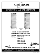
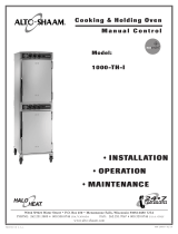
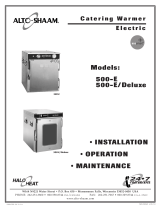
Rating & Certification
Identification Tag
Serial
Number
Tag
On/Off
Electrical
Power Switch
Hi-Limit
Button
Double Compartment Oven
1200-TH/III Control
This model has two ON/OFF Key
controls, one to control the top
cooking cavity, one to control the
bottom cooking cavity.
Each compartment is controlled
and programmed separately.
Double Oven Control
Model 1000-TH/III
Single Oven
Back of Unit
Hi-Limit Reset Button
1200-TH/III Double
Compartment Oven
SINGLE COMPARTMENT
INSTALLATION
DOUBLE COMPARTMENT CONTROL

#8311 INSTALLATION/OPERATION/SERVICE MANUAL PG. 13
OPERATING INSTRUCTIONS
USER SAFETY INFORMATION
The Alto-Shaam cook and hold oven is intended
for use in commercial establishments by qualified
operating personnel where all operators are
familiar with the purpose, limitations, and
associated hazards of this appliance. Operating
instructions and warnings must be read and
understood by all operators and users.
START-UP OPERATION
BEFORE INITIAL USE:
Interior oven surfaces must be heated to remove
surface oils and the accompanying odor produced
during the first use of the oven.
1. Wipe all wire shelves, side racks and the full
oven interior with a clean, damp cloth. Install
the oven side racks, oven shelves, and external
drip tray. Shelves are installed with the curved
edge toward the back of the oven. Insert the
drip pan on the interior bottom surface of
the oven.
2. Close the oven doors, press the power switch
to the on position, and set the thermostat to
300°F (149°C).
3. Allow the oven to cycle for approximately
2 hours or until no odor is detected.
PREHEATING:
Always preheat the oven for a minimum of 45
minutes before cooking product. Follow the
operating instructions indicated on the next page
of this manual.
AT NO TIME SHOULD THE INTERIOR OR
EXTERIOR BE STEAM CLEANED, HOSED
DOWN, OR FLOODED WITH WATER OR
LIQUID SOLUTION OF ANY KIND. DO NOT
USE WATER JET TO CLEAN.
SEVERE DAMAGE OR ELECTRICAL HAZARD
COULD RESULT.
WARRANTY BECOMES VOID IF APPLIANCE IS FLOODED.
METAL PARTS OF THIS EQUIPMENT
BECOME EXTREMELY HOT WHEN IN
OPERATION. TO AVOID BURNS,
ALWAYS USE HAND PROTECTION
WHEN OPERATING THIS APPLIANCE.

PG. 14 #8311 INSTALLATION/OPERATION/SERVICE MANUAL
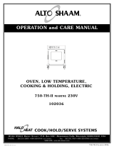
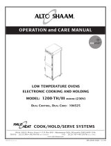
1. ON/OFF Key
The ON/OFF control system key operates the
functions of the control panel. If there is any
power loss during operation, the O
N/OFF indicator
light will flash. To clear, push key and release.
2. COOK Key — Temperature range 200° to 325°F
(93° to 162°C)
Used to select cooking mode and to review the cook
temperature setting.
3. TIME Key — Maximum time 24 hours
Used to select cook time and to review set time.
4. PROBE Key — Temperature range 50° to 195°F
(10° to 91°C)
Used to select internal product probe temperature
mode and to review probe temperature setting.
5. HOLD Key — Temperature range 60° to 205°F
(15° to 96°C)
Used to select food holding mode and to review set
holding temperature.
6. Lock Indicator
When illuminated, this symbol indicates settings
used in the cooking sequence are locked and
cannot be changed.
7. Halo Heat Indicator
When the oven is preheating, the Halo Heat
indicator will illuminate during preheating and
remain steady until the oven reaches the set
cooking temperature. When the temperature has
stabilized, the indicator will illuminate periodically
as the oven calls for heat.
8. Oven Preheat Light
Illuminates until the oven is preheated.
9. LED Display
Indicates interior oven air temperature, internal
product probe temperature, time, or when used in
conjunction with other keys, will review
original cooking, holding and probe temperature
settings. The display will also indicate various
programming and diagnostic information.
10. Ready Indicator Light
Illuminates when the oven has finished preheating.
11. UP and DOWN ARROWS
Used to increase or decrease set time, including
cooking, holding and probe temperature settings.
12. START Key
Used to initiate a selected mode sequence when
pressed and released. You may stop any mode of
operation by
pressing and holding the START Key
until you hear a beep.
13. Green Indicator Lights
Located within each function key, the green light
functions as an operator prompt indicating
additional operator action is required and also
identifies current mode of operation.
14. Amber Indicator Lights
Located below the COOK, TIME, PROBE and HOLD
Keys, these indicators will illuminate to identify
the current mode of operation and allows the
operator to identify the information currently
shown in the LED display.
15. PRESET Program Keys
Provides memory storage and operation of up to
eight operator set cooking programs for specific
products (A thru H). I enables locking abilities.
16. CANCEL Key
Used to erase a program from memory storage.
PRESETS
ABCDEFGHI CANCEL
CONTROL FEATURES
Do not use the oven if the controls are not properly functioning. Refer to the Trouble Shooting Guide located
in this manual or call an authorized service technician.
IMPORTANT
Single Oven Control
OPERATING INSTRUCTIONS

#8311 INSTALLATION/OPERATION/SERVICE MANUAL PG. 15
OVEN BEEPING is used to indicate a YES or NO response to operator input.
Beeps also indicate mode C
HANGES and ERROR conditions.
One brief beep indicates a YES (enabled) response to the information entered into the control.
Two brief beeps indicate a NO (disabled) response to the information entered into the control.
A beep that lasts for one second indicates an oven mode TRANSITION. Example: Preheat to Ready-Start.
Three brief beeps indicate the oven is in the READY mode for product loading and START-UP.
Four brief beeps indicate an existing FAULT condition. Refer to the Trouble Shooting section of this manual.
Beeper volume can be changed. With the control in the O
FF mode, press and hold the DOWN ARROW Key until the display
exhibits one of the 4 volume levels (0 being O
FF or the lowest, and 3 being the highest). After each change, the button must be
released and the display must clear before the procedure can be repeated to select a different volume level.
AUDIBLE SIGNALS
Turn the Oven Control Panel Off:
Press and hold the ON/OFF Key until the oven beeps. The ON/OFF
indicator light will go out.
Stop an Operation:
Press and hold the START Key for several seconds until the control
beeps, indicating the operation has been cancelled. The oven will
remain in a power-on state.
Arrow Keys:
Cook, Hold and Probe Temperature
set points can be adjusted by 1°
when pressing the A
RROW Keys. To change a set point more rapidly,
press and hold the ARROW Key along with the key for the temperature
function, and the temperature changes in steps of 10°F or 5°C.
The
Time setting is adjusted in increments of one minute by pressing
the A
RROW Keys. To make adjustment in steps of ten minutes, press
and hold
the TIME Key and ARROW Key at the same time.
Probe Usage:
When the oven probe remains inserted in the probe bracket, the LED
temperature display will indicate the ambient air temperature inside
the oven. To use the probe for cooking remove it from the bracket
and wipe the full length of the metal probe with a disposable alcohol
pad to clean and sanitize before using.
Only the tip of the probe senses the internal product temperature;
therefore, it is important the tip be placed correctly in the product for
internal temperature accuracy. Push the probe tip halfway into the
product, positioning the tip at the center of the food mass. When
inserting the probe into solid foods such as meat roast or poultry
breasts, push the probe in from a straight downward position or in
from the side to the center position. If placing into a semi-liquid or
liquid product, the probe cable must be secured to keep the probe
positioned properly. Do not let the probe tip touch the edges, bottom
or side of a container. Tape the probe cable to the lip or edge of
the container.
Display High/Low Probe Temperatures:
To observe the recorded maximum or minimum
probe temperature when cooking by probe, press
the following keys while the probe remains in the
product:
Highest Temperature: Press PROBE Key and UP
ARROW Key at same time.
Lowest Temperature: Press PROBE Key and DOWN
ARROW Key at same time.
Halo Heat Indicator:
When the oven is preheating the Halo Heat
indicator light will remain illuminated until it
reaches the set cook temperature. Once the
temperature has stabilized, this indicator will
illuminate periodically as the oven calls for heat.
Green and Amber Indicators:
Each program key includes a green light which
indicates a requirement for additional
programming by the operator or the current
operational state of the oven.
The C
OOK, TIME, PROBE, and
H
OLD keys include an amber
indicator light to identify the
information being displayed.
Power Fail Detect:
If the power were to fail for any reason while
heating, the control will retain, in memory, the
programmed operating conditions. When power
is restored, the control will resume operating
from the point where it was interrupted and the
O
N/OFF indicator light will flash, indicating that
such an event did occur. The operator can turn
off the flashing light by pressing the O
N/OFF key.
NOTE: If such an event has occurred, it is
strongly recommended that you ensure the food is
safe for consumption according to local health
regulations.
OPERATING FEATURES & FUNCTIONS
TIME
●
Amber
Green
NOTE
:
When cooking by probe, insert the probe into the raw
product after the oven has been preheated.
WAIT ONE FULL MINUTE
to allow the probe temperature to
decrease to the internal temperature of the product. Press the
start button to begin the cooking process after this probe
temperature adjustment period. A false probe reading of the
internal product temperature will cause the oven to default to a
holding temperature.
OPERATING INSTRUCTIONS

PG. 16 #8311 INSTALLATION/OPERATION/SERVICE MANUAL
Cook by Time: IS THE MAIN ELECTRICAL POWER SWITCH ON?
Press and release control O
N/OFF key.
• The green indicator light on the ON/OFF key will illuminate.
• The oven will beep for one second.
• The oven will begin operating in the hold mode.
• The amber hold indicator will illuminate.
• The previously set hold temperature will be displayed.
Press the HOLD Key.
➥To change the hold temperature, press the UP or DOWN ARROW Keys.
Note: If the oven is being used for hot food holding only, adjust the
set holding temperature. Do not press the COOK, TIME, or PROBE Keys.
Press COOK Key to preheat.
• The green indicator light on the COOK Key will
illuminate.
• Last set cooking temperature will be displayed.
➥To change the cook temperature, press the UP or
DOWN ARROW Keys.
• The green indicator light on the TIME Key and on
the PROBE Key alternately flash.
Press TIME Key.
• The green indicator light on the TIME Key will illuminate.
• Last set time is displayed.
➥To change the cook time, press the UP or DOWN ARROW Keys.
• The green indicator light on the TIME Key will illuminate.
• Halo Heat and Pre-Heat indicator will illuminate.
➥The oven is automatically programmed to preheat to the cook temperature.
• The oven will beep when preheated and the preheat indicator light will go out.
• Both the Ready and Start indicator lights will flash.
➥The set cook temperature will be maintained by the oven and appear in the display
while in the ready/start mode.
Load the food inside oven and close the oven door.
Note: The oven will beep 3 times every 25 seconds until the oven is loaded and the START
Key pressed.
Press and release START key.
COOK
• The oven will beep.
• The green indicators for power, cook, time, and start will illuminate.
• The display will alternate between showing the set cook temperature and the remaining time.
HOLD
• The oven will beep at the end of the timed cooking cycle.
• The green indicator for cook will remain illuminated.
• The display will alternate between showing the set hold temperature and the amount of
time the product has remained in the holding mode.
• The Ready indicator light will illuminate after 2 hours in the hold mode.
Note: The ready indicator does not necessarily indicate a product-ready state. For best
results, the product must remain in the oven at the set holding temperature for the
minimum number of hours indicated in the individual cooking instructions.
• The oven will remain operating in the hold mode until the control ON/OFF Key is pressed.
ON/OFF
START
HELPFUL HINT
To avoid prolonged
preheat times between
loads, leave the
oven in the
hold mode.
OPERATING INSTRUCTIONS
TO MAINTAIN SAFE TEMPERATURE LEVELS,
COLD FOOD FOR RETHERMALIZATION OR
REHEATING MUST NEVER BE ADDED TO THE
OVEN WHILE HOT FOODS ARE BEING HELD.

#8311 INSTALLATION/OPERATION/SERVICE MANUAL PG. 17
ON/OFF
START
Cook by Probe: IS THE MAIN ELECTRICAL POWER SWITCH ON?
Press and release control O
N/OFF Key.
• The green indicator light on the ON/OFF key will illuminate.
• The oven will beep for one second.
• The oven will begin operating in the hold mode.
• The amber hold indicator will illuminate.
• The previously set hold temperature will be displayed.
Press the HOLD Key.
➥To change the hold temperature, press the UP or DOWN ARROW Keys.
Note: If the oven is being used for hot food holding only, adjust the set holding
temperature. Do not press the COOK, TIME, or PROBE keys.
Press COOK Key to preheat.
• The green indicator light on the COOK Key will illuminate.
• Last set cooking temperature will be displayed.
➥To change the cook temperature, press the UP or DOWN ARROW Keys.
• The green indicator light on the TIME Key and on the PROBE Key alternately flash.
Press PROBE Key.
• The green indicator light on the PROBE Key will illuminate.
• Last set internal product temperature is displayed.
➥To change the internal product temperature, press the UP or DOWN ARROW Keys.
• The green indicator light on the PROBE Key will illuminate.
• Halo Heat and Pre-Heat indicator will illuminate.
➥The oven is automatically programmed to preheat to the cook temperature.
• The oven will beep when preheated and the preheat indicator extinguished.
• Both the Ready and Start indicator lights will flash.
➥The set cook temperature will be maintained by the oven and appear in the display
while in the ready/start mode.
Load the food inside oven. Remove probe from its bracket, wipe the probe tip with a disposable
alcohol pad and insert probe properly into the product. Close the oven door.
Note: Oven will beep 3 times every 25 seconds until oven is loaded and START Key pressed.
Press and release START key.
COOK
• The oven will beep.
• The green indicators for power, cook, probe, and start will illuminate.
• The display will alternate between showing the probe temperature and the elapsed time.
HOLD
• The oven will beep when the set probe temperature has been reached.
• The green indicator for cook will remain illuminated.
• The display will alternate between showing the set hold temperature and the amount of
time the product has remained in the holding mode.
• Ready indicator light will illuminate after 2 hours in the hold mode.
Note: The ready indicator does not necessarily indicate a product-ready state. For best
results, the product must remain in the oven at the set holding temperature for the
minimum number of hours indicated in the individual cooking instructions.
• The oven will remain operating in the hold mode until the control ON/OFF Key is pressed.
OPERATING INSTRUCTIONS
TO MAINTAIN SAFE TEMPERATURE LEVELS,
COLD FOOD FOR RETHERMALIZATION OR
REHEATING MUST NEVER BE ADDED TO THE
OVEN WHILE HOT FOODS ARE BEING HELD.

PG. 18 #8311 INSTALLATION/OPERATION/SERVICE MANUAL
Preset Menu Keys:
Alto-Shaam Cook and Hold ovens allow the operator to set up to eight cooking programs. Each cooking
program can be preset in any program mode to cook by time or internal product temperature. Cooking programs
are recalled and stored using the PRESET Keys labeled "A through H." These keys, along with the key labeled "I"
share additional functions described in the "User Options" section of this manual.
Programming a Cooking Program
Prior to this procedure, make sure the oven is “OFF”. Select the food product to be programmed.
Press and release control ON/OFF key. The oven will beep for one second and power to the unit
will be indicated by an illuminated green indicator light located in the upper left corner of the
ON/OFF key. The oven will begin operating in the hold mode. The amber hold indicator will be
illuminated and the last set hold temperature will be displayed.
Press HOLD Key. To change the hold temperature, press the UP or DOWN
ARROW Keys.
Press COOK Key. Oven preheat indicator will illuminate and the last set cooking temperature
is displayed. To change the cook temperature, press the UP or DOWN ARROW Keys.
To cook by time — press the TIME Key. Last set cooking time is displayed.
To change the set time, press the UP or DOWN ARROW Keys. The green Time
indicator will illuminate.
To cook by probe — press the PROBE Key. Last set internal product temperature is displayed.
To change the set temperature, press the UP or DOWN ARROW Keys. The green Probe indicator
will illuminate.
The oven preheat indicator will illuminate. Oven is now in the preheat mode and is
automatically programmed to preheat to the cook temperature.
Select a letter code for the product programmed by the previous steps. Press and hold the
selected PRESET key until you hear a brief, four second beep. The letter key program indicator
light will illuminate and the product programmed is now stored in memory for the specific letter
key pressed. Additional programs can be stored in the remaining PRESET Keys if not previously
programmed.
Note: The last PRESET Key used will be the oven cooking run sequence for the next product
to be programmed. Settings can be manually changed for the next product and an alternate
pre-programmed letter key selected.
Erasing a Cooking Program
To erase a program, the oven must be in either the power-up hold mode or in the preheat mode. The oven
cannot be running a Preset Menu program.
When the oven is in the power-up hold mode or in the preheat mode, press and hold both the CANCEL Key and
the appropriate letter PRESET Key to be erased. Hold both keys until the oven beeps and the program's indicator
light goes out to indicate the program has been erased.
ON/OFF
— or —
PRESETS
A
After programming a specific product into memory in a programmable preset key,
it is very important to make a written permanent record of the product and the program
letter assigned. Menu card (PE-23384) is provided for this purpose.
IMPORTANT
OPERATING INSTRUCTIONS
/