Page is loading ...

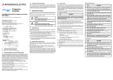
INVERTER
INSTRUCTION MANUAL
Filterpack
FR-BFP2-(H)0.4K to (H)15K
1. Product Checking............................................................ 1
2. Applicable Inverter........................................................... 1
3. Installation ....................................................................... 2
3.1 Inverter Installation (installation of the Filterpack)...............2
4. Wiring .............................................................................. 5
5. Main Circuit Terminal ...................................................... 6
6. Leakage Current.............................................................. 6
7. Rating Specifications....................................................... 6
8. Outline Dimension........................................................... 7

Thank you for choosing this Mitsubishi Electric Inverter option unit.
This Instruction Manual gives handling information and precautions for use of this equipment. Incorrect handling
might cause an unexpected fault. Before using the equipment, please read this manual carefully to use the equip-
ment to its optimum performance.
Please forward this Instruction Manual to the end user.
1. Electric Shock Prevention
2. Fire Prevention
3. Injury Prevention
4. Additional Instructions
Also note the following points to prevent an accidental failure,
injury, electric shock, etc.
1) Transportation and mounting
2) Usage
3) Disposal
4) General instruction
This section is specifically about safety matters
Do not attempt to install, operate, maintain or inspect this product until you have read through this instruction manual and
appended documents carefully and can use the equipment correctly. Do not use this product until you have a full knowledge of
the equipment, safety information and instructions.
In this instruction manual, the safety instruction levels are classified into "WARNING" and "CAUTION".
Assumes that incorrect handling may cause hazardous conditions, resulting in death or severe injury.
Assumes that incorrect handling may cause hazardous conditions, resulting in medium or slight
injury, or may cause physical damage only.
Note that even the level may lead to a serious consequence according to conditions. Please follow the
instructions of both levels because they are important to personal safety.
WARNING
CAUTION
CAUTION
SAFETY INSTRUCTION
WARNING
While power is ON or when the inverter is running, do not
open the terminal cover of the option unit. Doing so may
access the exposed high voltage terminals or the charging
part of the circuitry and cause an electric shock. Otherwise,
you may get an electric shock.
Before starting wiring or inspection, switch OFF power, wait
for at least 10 minutes after the power supply has been
switched OFF, and check that there are no residual voltage
using a tester or the like. The capacitor is charged with high
voltage for some time after power OFF and it is dangerous.
Any person who is involved in the wiring or inspection of
this equipment should be fully competent to do the work.
Always install the inverter and the option unit before wiring.
Otherwise, you may get an electric shock or be injured.
Do not touch the option unit or handle the cables with wet
hands. Otherwise you may get an electric shock.
Do not subject the cables to scratches, excessive stress,
heavy loads or pinching. Otherwise you may get an electric
shock.
CAUTION
Install this option unit on a nonflammable wall without
holes. Mounting it to or near flammable material can cause a
fire.
CAUTION
Apply only the voltage specified in the instruction manual
to each terminal. Otherwise, burst, damage, etc. may occur.
Ensure that the cables are connected to the correct termi-
nals. Otherwise, burst, damage, etc. may occur.
Always make sure that polarity is correct to prevent dam-
age, etc. Otherwise, burst, damage, etc. may occur.
While power is ON or for some time after power-OFF, do not
touch the option unit as they will be extremely hot. Doing so
can cause burns.
CAUTION
Transport the product using the correct method that corre-
sponds to the weight. Failure to observe this may lead to
injuries.
Do not install or operate the option unit if it is damaged or
has parts missing.
Do not stand or rest heavy objects on the product.
Check that the mounting orientation is correct.
Prevent other conductive bodies such as screws and metal
fragments or other flammable substance such as oil from
entering the inverter.
As this option unit is a precision instrument, do not drop or
subject it to impact.
If halogens (including fluorine, chlorine, bromine, and iodine)
contained in fumigants for wood packages enter this prod-
uct, the product may be damaged. Prevent the entry of fumi-
gant residuals or use an alternative method such as heat
disinfection. Note that sterilization or disinfection of wood
packages should be performed before packing the product.
Use this option unit under the following environmental con-
ditions: Otherwise, the option unit may be damaged
*1 Temperature applicable for a short time, e.g. in transit.
*2 When installing the Filterpack of 11K or 15K on the rear side of the
inverter, do not install on moving objects or places which vibrates
(exceeding 1.96m/s
2
).
WARNING
Do not modify the equipment.
Do not perform parts removal which is not instructed in this
manual. Doing so may lead to fault or damage of the prod-
uct.
CAUTION
Treat as industrial waste.
All of the diagrams and drawings in this Instruction Manual
show the option unit without a terminal cover, or partially
open. Never operate the products in this manner. Always
replace the cover and follow this Instruction Manual when
operating the products.
Environment
Surrounding air
temperature
-10
°C
to +50
°C
(non-freezing)
Ambient
humidity
90%RH maximum (non-condensing)
Storage
temperature
-20
°C
to +65
°C
*1
Atmosphere
Indoors (free from corrosive gas, flammable
gas, oil mist, dust and dirt)
Altitude/
vibration
Maximum 1,000m above sea level. 5.9m/s
2
or
less at 10 to 55Hz (directions of X, Y, Z axes) *2

1
This option is a dedicated Filterpack unit for FR-E800 series, FR-E700 series, FR-D700 series, and FR-
F700PJ series, which contains a DC reactor, common mode choke and capacitive filter.
1. Product Checking
Unpack the option unit and confirm that the product is as you ordered and intact.
Filterpack type
Accessories
* The screw size differs according to capacities. ((H)7.5K or lower: M4×14, (H)11K, (H)15K: M5×20)
2. Applicable Inverter
Use the Filterpack along with the inverter in the following table.
* Select the capacity to make the load current (inverter output) lower than the permissible inverter output current.
Parts name and plate
Name Description Quantity
Refer to
page
Screw for leakage current
countermeasure and spacer
When the earth leakage breaker or earth leakage relay operates
unnecessarily due to leakage current, use this screw as a
countermeasure.
1 for each 6
Rear panel installation L-
bracket
Included with the 5.5K or higher 1 2
Screw for inverter rear panel
installation
Use these screws for installation of the Filterpack onto the inverter
rear panel.
4* 2
Filterpack
Applicable inverter
Permissible inverter
output current (A)
*
D700 F700PJ E700 E800
FR-BFP2-0.4K FR-D720-0.4K FR-F720PJ-0.4K FR-E720-0.4K FR-E820-0.4K 2.5
FR-BFP2-0.75K FR-D720-0.75K FR-F720PJ-0.75K FR-E720-0.75K FR-E820-0.75K 4.2
FR-BFP2-1.5K FR-D720-1.5K FR-F720PJ-1.5K FR-E720-1.5K FR-E820-1.5K 7
FR-BFP2-2.2K FR-D720-2.2K FR-F720PJ-2.2K FR-E720-2.2K FR-E820-2.2K 10
FR-BFP2-3.7K FR-D720-3.7K FR-F720PJ-3.7K FR-E720-3.7K FR-E820-3.7K 16.5
FR-BFP2-5.5K FR-D720-5.5K FR-F720PJ-5.5K FR-E720-5.5K FR-E820-5.5K 23.8
FR-BFP2-7.5K FR-D720-7.5K FR-F720PJ-7.5K FR-E720-7.5K FR-E820-7.5K 31.8
FR-BFP2-11K FR-D720-11K FR-F720PJ-11K FR-E720-11K - 45
FR-BFP2-15K FR-D720-15K FR-F720PJ-15K FR-E720-15K - 58
FR-BFP2-H0.4K FR-D740-0.4K FR-F740PJ-0.4K FR-E740-0.4K FR-E840-0.4K 1.2
FR-BFP2-H0.75K FR-D740-0.75K FR-F740PJ-0.75K FR-E740-0.75K FR-E840-0.75K 2.2
FR-BFP2-H1.5K FR-D740-1.5K FR-F740PJ-1.5K FR-E740-1.5K FR-E840-1.5K 3.7
FR-BFP2-H2.2K FR-D740-2.2K FR-F740PJ-2.2K FR-E740-2.2K FR-E840-2.2K 5
FR-BFP2-H3.7K FR-D740-3.7K FR-F740PJ-3.7K FR-E740-3.7K FR-E840-3.7K 8.1
FR-BFP2-H5.5K FR-D740-5.5K FR-F740PJ-5.5K FR-E740-5.5K FR-E840-5.5K 12
FR-BFP2-H7.5K FR-D740-7.5K FR-F740PJ-7.5K FR-E740-7.5K FR-E840-7.5K 16.3
FR-BFP2-H11K FR-D740-11K FR-F740PJ-11K FR-E740-11K - 23
FR-BFP2-H15K FR-D740-15K FR-F740PJ-15K FR-E740-15K - 29.5
FR-BFP2- H K
0.4 to 15
Represents the applicable inverter capacity
Symbol
Applicable power voltage
None
200V class
400V class
H
Installation hole
Inverter rear panel
installation screw hole
Power supply connection terminal bloc
k
Black cable: connect to terminal R, S and T of the inverter
Red cable: connect to terminal P and P1 of the inverter
Green and yellow striped cable: connect to the earth (ground) terminal
Crimping terminals for the inverter connection
Rating plate
Terminal block cover
Filter
pack type
Rating
SERIAL
number
MODEL
FR-BFP2-H0.4K
BKO-
RATED
SERIAL
MITSUBISHI ELECTRIC CORPORATION
Earth (Ground) terminal

2
3. Installation
3.1 Inverter Installation (installation of the Filterpack)
3.1.1 Installation of the inverter and Filterpack (for rear panel installation)
0.4K to 3.7K (except for FR-E820-3.7K)
Remove the front cover and wiring cover to attach the inverter.
FR-E820-3.7K
Screw for inverter rear
panel installation
Screw for inverter rear
panel installation
Front cover
Screw for inverter rear
panel installation
Front cover
Screw for inverter rear
panel installation
Wiring cover
Wiring cover
Front cover
Screw for inverter rear
panel installation
Screw for inverter rear
panel installation
Wiring cover

3
5.5K to 15K
Remove the L-bracket installation screws from the Filterpack (two for the 7.5K or lower, three for the 11K or
higher), and attach the included L-bracket to the Filterpack with these screws.
Remove the front cover to attach the inverter.
CAUTION
When installing the Filterpack to the inverter, use the included installation screws for the inverter rear panel. Using a longer
screw may damage the Filterpack.
Rear panel installation is not available for FR-E720-5.5K and 7.5K, FR-E740-0.4K to 3.7K.
Rear panel installation L-bracket
L-bracket installation screw
Screw for inverter
rear panel installation
Screw for inverter rear panel installation

4
3.1.2 Installation of the Filterpack
The following installations are recommended for the Filterpack and inverter.
When encasing multiple inverters, install them in parallel as a cooling measure.
Install the inverter (Filterpack) vertically.
Side-by-side installation is not available for Filterpacks.
For wiring of the Filterpack and inverter, refer to page 5
Installation of the inverter and Filterpack
Install the Filterpack cable carefully without subjecting it to excessive stress when wiring. Also be careful not
to damage the cable with sharp items such as an edge of a metal sheet.
To prevent malfunctions and damages, never perform installations in the following manner. Only install
according to the recommended mounting methods.
Rear panel installation Side panel installation
Underneath installation
Invert installation of the Filterpack Sideway installation of the Filterpack
Filterpack
Filterpack
1cm
CAUTION
When installing the Filterpack of 11K or 15K on the rear
panel of the inverter, do not install on moving objects or
places which vibrate (exceeding 1.96m/s
2
).
CAUTION
To release heat of the inverter and Filterpack, leave
clearance of 1 cm or more when installing the inverter and
Filterpack.
Filterpack
10cm
CAUTION
Install the Filterpack with the wiring portion facing right.
Underneath installation is not available for 11K and 15K.
To release heat, leave clearance of 10cm or more between
the inverter and Filterpack.

5
4. Wiring
Wire the Filterpack and the inverter according to the following connection diagram. Connect the Filterpack to
an input side of the inverter. After wiring, attach the terminal cover of the Filterpack to the terminal block.
Connection diagram
*1 Connect the GND cable of the Filterpack to the earth (ground) terminal of the inverter.
Use the earth (ground) terminal of the Filterpack to
earth (ground). The inverter is earthed (grounded) through the Filterpack.
*2 For cable size for MCCB, MC and Filterpack, refer to the inverter Instruction Manuals.
MCCB and MC should be selected with reactor connection.
Wiring of the inverter and Filterpack
Perform wiring of the inverter and Filterpack in the following procedure.
(1) Connect the commercial power supply to the terminal R0, S0 and T0 of the Filterpack.
(2) Connect the earth (ground) cable (green and yellow striped cable) of the Filterpack to the inverter earth (ground)
terminal.
(3) Connect the power supply cable (black cable) of the Filterpack to the terminal R, S and T.
(4) Remove the jumper across terminals P and P1 of the inverter, and connect the P and P1 cables (red cable) of the
Filterpack.
(5) Connect the motor cable to the inverter output terminals (U, V, W). (Match the phase sequence.)
REMARKS
Phase sequence need not be matched.
CAUTION
Make sure that the power cables are connected to the R0, S0 and T0 of the Filterpack. (Phase sequence need not be
matched.)
Never connect the power cable to the U, V, W of the inverter. Doing so will damage the inverter.
When connecting the Filterpack, make sure that the jumper across the terminals P and P1 of the inverter is removed.
Connect the Filterpack terminals P and P1 to the inverter terminals P/+ and P1, respectively. Improper connection may dam-
age the inverter.
MCCB MC
Three-phase
A
C power
supply
R/L
1
S/L
2
T/L
3
P/+
P1
N/-
Jumper: Remove this
jumper to connect the
Filterpack.
POINT
R0
S0
T0
P1
P
Filterpack
FR-BFP2
*1
*2 *2
GND
R
S
T
Inverter
Motor
M
Earth
(Ground)
V
W
U
N/- P/ +
P1
VW
U
R/L1 S/L2 T/L3
S0 T0
R0
R
S
T
Remove the jumper.
M
U
V
W
T
P
S
R
P1
Power supply
motor
GND
Filterpack

6
5. Main Circuit Terminal
* The terminal screw size is the same as that of the inverter terminal R, S and T.
6. Leakage Current
When using the Filterpack, the leakage current is about 4mA (8mA for the 400V class)(for one phase of the
three-phase three wire connection current).
When using the Filterpack, leakage current will be reduced by removing the earth (ground) cable of the
capacitive filter, and fixing it with the included screw for leakage current countermeasure (plastic) and spacer
(plastic). However, the noise reduction effect of the capacitive filter will be lost.
(Pull out the earth (ground) cable slightly to wire the capacitive filter.)
Installation
7. Rating Specifications
200V class
400V class
*1 The values in parentheses are calculated by applying 1 power factor to the reference waveform in accordance with the Architectural
Standard Specifications (Electrical Installation) (2010 revisions) in Japan.
*2 * The indicated leakage current is equivalent to one-phase of the three-phase three wire connection cable.
Terminal symbol Terminal name Description
R0, S0, T0* Commercial power supply input Connect to the commercial power supply.
Earth (Ground) The Filterpack must be earthed (grounded).
Crimping terminal
symbol
Terminal name Cable color Description
R, S, T Inverter power supply Black Connect to the R, S, T of the inverter.
P, P1 DC reactor terminal Red
Remove the jumper across terminals P and P1, and
connect to the terminals P and P1 of the inverter.
GND
Inverter earth (ground)
connection
Green and yellow
stripes
Connect to the earth (ground) terminal of the inverter.
(Refer to page 5)
CAUTION
When the earth (ground) cable for the capacitive filter is removed, the cable is charged while power is ON or shortly after power
OFF. Do not touch the earth (ground) cable as you may get an electric shock.
Type FR-BFP2-K 0.4 0.75 1.5 2.2 3.7 5.5 7.5 11 15
Approximate mass (kg) 1.3 1.4 2.0 2.2 2.8 3.8 4.5 6.7 7.0
Power factor improving reactor
Install the DC reactor in the DC side.
93% to 95% (94.4% *1) of power supply power factor under 100% load
Noise filter
Common mode choke Install a ferrite core on the input side
Capacitive filter About 4mA of capacitor leakage current *
Protective structure (JEM1030) Open type (IP00)
Type FR-BFP2-HK 0.4 0.75 1.5 2.2 3.7 5.5 7.5 11 15
Approximate mass (kg) 1.6 1.7 1.9 2.3 2.6 4.5 5.0 7.0 8.2
Power factor improving reactor
Install the DC reactor in the DC side.
93% to 95% (94.4% *1) of power supply power factor under 100% load
Noise filter
Common mode choke Install a ferrite core on the input side
Capacitive filter About 8mA of capacitor leakage current *2
Protective structure (JEM1030) Open type (IP00)
Spacer
(plastic)
Screw for leakage current countermeasure (plastic)
(tightening torque: 0.35 0.05Nm)
Earth (ground) cable
for capacitive filter
Filterpack

7
8. Outline Dimension
FR-BFP2-0.4K, 0.75K
5
30
60
4.5
15
1.6
15
2085 5
1.6
30
68
19
4.5
19
218
208 5
2-φ4.5 hole
2-φ4.5 hole
240
220
(GND) (R) (S) (P1) (P)(T)
Rating
plate
Crimp ring terminalφ4.3
Unitmm

8
FR-BFP2-1.5K, 2.2K, 3.7K
FR-BFP2-H0.4K, H0.75K, H1.5K, H2.2K, H3.7K
1.6
12.5
4.5
12.5
178
5
5
178
188
55
1.6
W2
W
W1
W2
4.5
L1
L
2-
I 4.5 hole
(GND)
(R)
(S)
(P1)(P)
2-I 4.5 hole
(T)
D1
D
(*1)
Rating
plate
Crimp ring terminalI4.3
(*2)
200V power supply
(Unit: mm)
400V power supply
(Unit: mm)
*1 The 400V class H0.4K and H0.75K have no slit.
*2 These installation holes are provided for the FR-BFP2-3.7K only.
Capacity W W1 W2 D D1 L L1
1.5K, 2.2K 108 55 26.5 80 55 200 220
3.7K 170 120 25 65 40 220 240
Capacity W W1 W2 D D1 L L1
H0.4K, H0.75K* 108 55 26.5 55 30 200 220
H1.5K, H2.2K, H3.7K 108 55 26.5 80 55 200 220

9
FR-BFP2-5.5K, 7.5K, 11K, 15K
FR-BFP2-H5.5K, H7.5K, H11K, H15K
D
12.5
C1
C1
12.5
2.3
D1
H1
H
145
195
220
H2
25
(25)
25
2.3
H2
L
L-bracket for rear
panel installation of
the inverter
(enclosed)
2-
φC hole
2-
φC hole
Crimp ring terminal
φC2
(GND)
(R)
(S)
(P1)
(P)
(T)
Rating
plate
H1
H2
H2
L1
310
200V power supply
(Unit: mm)
400V power supply
(Unit: mm)
Capacity H H1 H2 D D1 C C1 C2 L L1
5.5K, 7.5K 210 198 6 75 50 4.5 4.5 5.3 270 400
11K 320 305 7.5 85 60 6 6 5.3 280 280
15K 320 305 7.5 85 60 6 6 6.4 260 260
Capacity H H1 H2 D D1 C C1 C2 L L1
H5.5K, H7.5K 210 198 6 75 50 4.5 4.5 4.3 270 400
H11K 320 305 7.5 85 60 6 6 4.3 280 280
H15K 320 305 7.5 85 60 6 6 6.4 260 260

10
Appendix Restricted Use of Hazardous Substances in Electronic
and Electrical Products
The mark of restricted use of hazardous substances in electronic and electrical products is applied to the
product as follows based on the “Management Methods for the Restriction of the Use of Hazardous Sub-
stances in Electrical and Electronic Products” of the People's Republic of China.
电器电子产品有害物质限制使用标识要求
本产品中所含有的有害物质的名称、含量、含有部件如下表所示。
·产品中所含有害物质的名称及含量
上表依据SJ/T11364的规定编制。
○:表示该有害物质在该部件所有均质材料中的含量均在GB/T26572规定的限量要求以下。
×:表示该有害物质在该部件的至少一种均质材料中的含量超出GB/T26572规定的限量要求。
*1 即使表中记载为 ×,根据产品型号,也可能会有有害物质的含量为限制值以下的情况。
*2 根据产品型号,一部分部件可能不包含在产品中。
环境保护使用
期限标识
部件名称
有害物质
铅
(Pb)
汞
(Hg)
镉
(Cd)
六价铬
(Cr(VI))
多溴联苯
(PBB)
多溴二苯醚
(PBDE)
电路板组件 (
包括印刷电路板及其构成的零部件,
如电阻、电容、集成电路、
连接器等)、电子部件
金属壳体、金属部件
树脂壳体、树脂部件
螺丝、电线

11

12

13
REVISIONS
*The manual number is given on the bottom left of the back cover.
Print Date
*
Manual Number
Revision
Jan. 2009 IB(NA)-0600378ENG-A First edition
Jun. 2011 IB(NA)-0600378ENG-B
Earth (ground) cable (GND) length for FR-BFP2-(H)5.5K and 7.5K.
Jun. 2020 IB(NA)-0600378ENG-C
Combination table for FR-E800
Installation holes of FR-BFP2-3.7K
Modification
Addition
IB(NA)-0600378ENG-C

/