Page is loading ...

UC15 MUX User Guide
UMTS/HSPA Module Series
Rev. UC15_MUX_User_Guide_V1.0
Date: 2014-07-11
www.quectel.com

UMTS/HSPA Module Series
UC15 MUX User Guide
UC15_MUX_User_Guide Confidential / Released 1 / 35
Our aim is to provide customers with timely and comprehensive service. For any
assistance, please contact our company headquarters:
Quectel Wireless Solutions Co., Ltd.
Office 501, Building 13, No.99, Tianzhou Road, Shanghai, China, 200233
Tel: +86 21 5108 6236
Mail: info@quectel.com
Or our local office, for more information, please visit:
http://www.quectel.com/support/salesupport.aspx
For technical support, to report documentation errors, please visit:
http://www.quectel.com/support/techsupport.aspx
GENERAL NOTES
QUECTEL OFFERS THIS INFORMATION AS A SERVICE TO ITS CUSTOMERS. THE INFORMATION
PROVIDED IS BASED UPON CUSTOMERS’ REQUIREMENTS. QUECTEL MAKES EVERY EFFORT
TO ENSURE THE QUALITY OF THE INFORMATION IT MAKES AVAILABLE. QUECTEL DOES NOT
MAKE ANY WARRANTY AS TO THE INFORMATION CONTAINED HEREIN, AND DOES NOT ACCEPT
ANY LIABILITY FOR ANY INJURY, LOSS OR DAMAGE OF ANY KIND INCURRED BY USE OF OR
RELIANCE UPON THE INFORMATION. ALL INFORMATION SUPPLIED HEREIN IS SUBJECT TO
CHANGE WITHOUT PRIOR NOTICE.
COPYRIGHT
THIS INFORMATION CONTAINED HERE IS PROPRIETARY TECHNICAL INFORMATION OF
QUECTEL CO., LTD. TRANSMITTABLE, REPRODUCTION, DISSEMINATION AND EDITING OF THIS
DOCUMENT AS WELL AS UTILIZATION OF THIS CONTENTS ARE FORBIDDEN WITHOUT
PERMISSION. OFFENDERS WILL BE HELD LIABLE FOR PAYMENT OF DAMAGES. ALL RIGHTS
ARE RESERVED IN THE EVENT OF A PATENT GRANT OR REGISTRATION OF A UTILITY MODEL
OR DESIGN.
Copyright © Quectel Wireless Solutions Co., Ltd. 2014. All rights reserved.
Quectel
Confidential

UMTS/HSPA Module Series
UC15 MUX User Guide
UC15_MUX_User_Guide Confidential / Released 2 / 35
About the Document
History
Revision
Date
Author
Description
1.0
2014-07-11
Max TANG
Initial
Quectel
Confidential

UMTS/HSPA Module Series
UC15 MUX User Guide
UC15_MUX_User_Guide Confidential / Released 3 / 35
Contents
About the Document ................................................................................................................................... 2
Contents ....................................................................................................................................................... 3
Table Index ................................................................................................................................................... 5
Figure Index ................................................................................................................................................. 6
1 Introduction .......................................................................................................................................... 7
2 The Design Purpose of MUX ............................................................................................................... 8
3 MUX AT Command ............................................................................................................................... 9
3.1. AT+CMUX Enable/disable MUX Control Channel .................................................................. 9
4 The Multiplexer Protocol ................................................................................................................... 11
4.1. Frame Structure ..................................................................................................................... 11
4.1.1. Flag Field ........................................................................................................................ 11
4.1.2. Address Field ................................................................................................................. 11
4.1.2.1. EA .......................................................................................................................... 11
4.1.2.2. C/R ......................................................................................................................... 11
4.1.3. Control Field ................................................................................................................... 12
4.1.4. Length Field.................................................................................................................... 13
4.1.5. Information Field ............................................................................................................ 13
4.1.6. FCS Field ....................................................................................................................... 13
4.2. Frame Type............................................................................................................................ 14
4.2.1. SAMB ............................................................................................................................. 14
4.2.2. UA................................................................................................................................... 14
4.2.3. DISC ............................................................................................................................... 14
4.2.4. DM .................................................................................................................................. 15
4.2.5. UIH ................................................................................................................................. 15
4.3. Control Channel ..................................................................................................................... 15
4.3.1. Message Format ............................................................................................................ 15
4.3.2. Message Type and Actions ............................................................................................ 16
4.3.2.1. Power Saving Control (PSC) ................................................................................. 16
4.3.2.2. Multiplexer Close Down ......................................................................................... 16
4.3.2.3. Flow Control on Command (FCon) ....................................................................... 17
4.3.2.4. Flow Control off Command (FCoff) ....................................................................... 17
4.3.2.5. Modem Status Command (MSC) .......................................................................... 17
4.4. Procedure .............................................................................................................................. 20
4.4.1. MUX Establishment ........................................................................................................ 20
4.4.2. MUX Release ................................................................................................................. 20
4.4.3. Data Transfer .................................................................................................................. 21
4.4.3.1. Information Data .................................................................................................... 21
4.4.3.2. Time-out Considerations ....................................................................................... 21
4.4.3.3. Flow Control ........................................................................................................... 22
Quectel
Confidential

UMTS/HSPA Module Series
UC15 MUX User Guide
UC15_MUX_User_Guide Confidential / Released 4 / 35
5 Power Saving Mode Under MUX ...................................................................................................... 23
5.1. Power Saving Mode Based on DTR Pin Only ....................................................................... 23
5.1.1. Host Enables Module to Enter into Power Saving Mode ............................................... 24
5.1.2. Host Enables Module to Exit from Power Saving Mode ................................................ 25
5.1.3. Module Enables Host to Exit from Power Saving Mode ................................................ 25
5.2. Power Saving Mode Based on PSC Frame and DTR Pin .................................................... 26
5.2.1. Host Enables Module to Enter into Power Saving Mode ............................................... 27
5.2.2. Host Enables Module to Exit from Power Saving Mode ................................................ 28
5.2.3. Module Enables Host to Exit from Power Saving Mode ................................................ 28
6 Example .............................................................................................................................................. 29
6.1. Samples for Frame Structure ................................................................................................ 29
6.2. Establish Channels ................................................................................................................ 30
6.3. Frame Transmission .............................................................................................................. 31
6.4. Power Saving Mode and Wake Up ....................................................................................... 32
6.5. Flow Control .......................................................................................................................... 32
6.6. Synchronization ..................................................................................................................... 33
6.7. Closing Down Multiplexers .................................................................................................... 34
7 Appendix A Reference ....................................................................................................................... 35
Quectel
Confidential

UMTS/HSPA Module Series
UC15 MUX User Guide
UC15_MUX_User_Guide Confidential / Released 5 / 35
Table Index
TABLE 1: MUX FRAME STRUCTURE ............................................................................................................... 11
TABLE 2: ADDRESS FIELD ............................................................................................................................... 11
TABLE 3: C/R .................................................................................................................................................... 12
TABLE 4: THE CODING OF CONTROL FIELD ................................................................................................ 12
TABLE 5: THE STRUCTURE OF LENGTH FIELD ........................................................................................... 13
TABLE 6: MAPPING FROM THE CONTROL SIGNAL OCTET BY A RECEIVING ENTITY ............................. 19
TABLE 7: MAPPING TO THE CONTROL SIGNAL OCTET BY A SENDING ENTITY ...................................... 19
TABLE 8: AT COMMAND CONFIGURATION BASED ON DTR PIN ................................................................ 23
TABLE 9: AT COMMAND CONFIGURATION BASED ON PSC FRAME AND DTR PIN.................................. 26
TABLE 10: RELATED DOCUMENTS ................................................................................................................ 35
TABLE 11: TERMS AND ABBREVIATIONS ...................................................................................................... 35
Quectel
Confidential

UMTS/HSPA Module Series
UC15 MUX User Guide
UC15_MUX_User_Guide Confidential / Released 6 / 35
Figure Index
FIGURE 1: MUX ARCHITECTURE ..................................................................................................................... 8
FIGURE 2: UA FRAME (RESPONSE) .............................................................................................................. 14
FIGURE 3: POWER SAVING FLOW CHART (1) .............................................................................................. 24
FIGURE 4: POWER SAVING FLOW CHART (2) .............................................................................................. 27
Quectel
Confidential

UMTS/HSPA Module Series
UC15 MUX User Guide
UC15_MUX_User_Guide Confidential / Released 7 / 35
1 Introduction
This document mainly introduces the technical details of Quectel MUX (Multiplexer Protocol) and provides
examples on how to develop MUX on devices.
Quectel
Confidential

UMTS/HSPA Module Series
UC15 MUX User Guide
UC15_MUX_User_Guide Confidential / Released 8 / 35
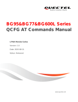
2 The Design Purpose of MUX
As to a non-multiplexer device, it is so inefficient to deal with only one kind or one channel of data steam
during a period of time. Therefore, Quectel multiplexer is designed to create 4 virtual channels on a
physical port in order to transmit data simultaneously. It looks like four real physical channels for the
application. They could operate the logical action on every virtual channel, such as using the SMS service
or PPP dialing.
All the data from APP is packed as the frames, and the frames consist of the data and protocol field which
clearly indicate the channel No., the length of the information and the FCS and so on. The frames are
transmitted as one stream via the serial port. After arriving at the other peer, they are unpacked as four
streams by the MUX protocol stack and transmitted to the application. Besides the information data, the
control signals are also simulated.
TE
UE
Application
DLC4
DLC3
DLC2
DLC1
MUX Driver
Physical Layer
DATA
MUX Driver
APP TASK
DLC4
DLC3
DLC2
DLC1
MUX Driver
Physical Layer
DATA
DS MUX TASK
Multi DATA
Figure 1: MUX Architecture
Quectel
Confidential

UMTS/HSPA Module Series
UC15 MUX User Guide
UC15_MUX_User_Guide Confidential / Released 9 / 35
3 MUX AT Command
3.1. AT+CMUX Enable/disable MUX Control Channel
This command is used to enable/disable the MUX control channel. The AT command sets parameters for
the control channel. If the parameters are left out, the default value will be used.
Parameter
AT+CMUX Enable/disable MUX Control Channel
Test Command
AT+CMUX=?
Response
+CMUX: (list of supported <mode>)[,(list of supported
<subset>)[,(list of supported <portspeed>)[,(list of
supported <N1>)[,(list of supported <T1>)[,(list of
supported <N2>)[,(list of supported <T2>)[,(list of
supported <T3>)[,(list of supported <k>)]]]]]]]]
OK
Read Command
AT+CMUX?
Response
+CMUX:
<mode>[,<subset>[,<portspeed>[,<N1>[,<T1>[,<N2>[,<T2
>[,<T3>[,<k>]]]]]]]]
OK
Write Command
AT+CMUX=<mode>[,<subset>[,<port
speed>[,<N1>[,<T1>[,<N2>[,<T2>[,<T3
>[,<k>]]]]]]]]
Response
OK
<mode> 0 Basic option.
<subset> This parameter defines the way in which the MUX control channel is set up.
Virtual channel may subsequently be set up differently, but in the absence of any
negotiation for the settings of a virtual channel, it shall be set up according to the
control channel <subset> setting.
0 UIH frames used only.
1 UI frames used only.
Quectel
Confidential

UMTS/HSPA Module Series
UC15 MUX User Guide
UC15_MUX_User_Guide Confidential / Released 10 / 35
Example
AT+CMUX=0
OK
AT+CMUX?
+CMUX: 0,0,5,127,10,3,30,10,2
OK
AT+CMUX can only be executed on UART1 since UC15 only supports MUX function via UART1.
2 I frames used only.
<portspeed> 1 9600bit/s
2 19200bit/s
3 38400bit/s
4 57600bit/s
5 115200bit/s
6 230400bit/s
7 460800bit/s
<N1> Maximum frame size, the range is 1-32768, 127 is the default value for basic
option (see <mode>).
<T1> The time UE waits for an acknowledgement before resorting to other action (e.g.
transmitting a frame).The step size is ten milliseconds, the range is 1-255. The
default value is 100ms.
<N2> Maximum number of re-transmissions, the range is 0-255, the default value is 3.
<T2> Response timer for MUX control channel, the step size is ten milliseconds, the
range is 2-255, 30 is the default value.
<T3> Wake up response timer in seconds. The range is 1-255, 10 is the default value.
<k> Window size (It is not supported for UC15).
NOTE
Quectel
Confidential

UMTS/HSPA Module Series
UC15 MUX User Guide
UC15_MUX_User_Guide Confidential / Released 11 / 35
4 The Multiplexer Protocol
This chapter explains the technical details of the multiplexer protocol.
4.1. Frame Structure
Table 1: MUX Frame Structure
4.1.1. Flag Field
Each frame begins and ends with a flag octet (0xF9).
4.1.2. Address Field
Table 2: Address Field
4.1.2.1. EA
EA is always set to 1.
4.1.2.2. C/R
C means the command and R means the response. TE sends a command to the module with C/R=1, and
the module responses with C/R=1. The module sends a command with C/R=0, and the TE responses
with C/R=0.
FLAG
Address
Control
Length
Information
FCS
FLAG
1 octet
1 octet
1 octet
1~2 octet
Multiple octets
1 octet
1 octet
Bit 1
Bit 2
Bit 3
Bit 4
Bit 5
Bit 6
Bit 7
Bit 8
EA
C/R
DLCI
Quectel
Confidential

UMTS/HSPA Module Series
UC15 MUX User Guide
UC15_MUX_User_Guide Confidential / Released 12 / 35
Table 3: C/R
The DLCI identifies the virtual channel between TE and UE. Multiple DLCIs shall be supported but the
number is implementation-specific. The DLCIs are dynamically assigned.
4.1.3. Control Field
Table 4: The Coding of Control Field
P/F is the Poll/Final bit. The poll (P) bit set to 1 shall be used by a station to solicit (poll) a response or
sequence of responses from the other station.
The final (F) bit set to 1 shall be used by a station to indicate the response frame transmitted as the result
of a soliciting (poll) command.
The poll/final (P/F) bit shall serve a function in both command frames and response frames (In command
frames, the P/F bit refers to the P bit. In response frames, it refers to the F bit). Following is detailed rules:
When DCE sends message frame, P/F is set to 0.
When DCE receives message frame from DLC0, whose P/F is set to 1, DCE will give priority to
response it and set response frame’s P/F to 1.
When DCE sends control frame, P/F is set to 1.
Command/Response
Direction
C/R Value
Command
TE→UE
1
UE→TE
1
Response
UE→TE
0
TE→UE
0
Frame Type
HEX (P/F=0)
1
2
3
4
5
6
7
8
SABM (Set Asynchronous Balanced Mode)
0x2F
1
1
1
1
P/F
1
0
0
UA (Unnumbered Acknowledgement)
0x63
1
1
0
0
P/F
1
1
0
DM (Disconnected Mode)
0x0F
1
1
1
1
P/F
0
0
0
DISC (Disconnect)
0x43
1
1
0
0
P/F
0
1
0
UIH (Unnumbered Information with Header
Check )
0xEF
1
1
1
1
P/F
1
1
1
UI (Unnumbered)
0x03
1
1
0
0
P/F
0
0
0
Quectel
Confidential

UMTS/HSPA Module Series
UC15 MUX User Guide
UC15_MUX_User_Guide Confidential / Released 13 / 35
When DCE sends UIH frame NOT by DLC0, P/F is set to 0.
DCE only process SABM, DISC frame, whose P/F is set to 1.
4.1.4. Length Field
Table 5: The Structure of Length Field
The L1 to L7 bits indicates the length of the following data field for the information field less than 128.
The range of the length field may be extended using the EA bit. When the EA bit is set to 1 in an octet, it is
signifies that this octet is the last octet of the length field. When the EA bit is set to 0, it signifies that a
second octet of the length field follows. The total length of the length field is 15 bits in that case.
4.1.5. Information Field
The information field is the payload of the frame and carries the user data and any convergence layer
information. The field is octet structured. The information field only presents in I frames, UI frames and
UIH frames.
4.1.6. FCS Field
In the case of the UIH frame, the contents of the I-field shall not be included in the FCS calculation. FCS is
calculated on the contents of the address, control and length fields only. This means that only the delivery
to the correct DLCI is protected, but not the information.
Bit 1
Bit 2
Bit 3
Bit 4
Bit 5
Bit 6
Bit 7
Bit 8
E/A
L1
L2
L3
L4
L5
L6
L7
Bit 1
Bit 2
Bit 3
Bit 4
Bit 5
Bit 6
Bit 7
Bit 8
0
L1
L2
L3
L4
L5
L6
L7
Bit 1
Bit 2
Bit 3
Bit 4
Bit 5
Bit 6
Bit 7
Bit 8
L8
L9
L10
L11
L12
L13
L14
L15
Quectel
Confidential

UMTS/HSPA Module Series
UC15 MUX User Guide
UC15_MUX_User_Guide Confidential / Released 14 / 35
4.2. Frame Type
4.2.1. SAMB
SABM is command frame and shall be used to establish DLC between TE and MS.
4.2.2. UA
UA frame is the response to SABM or DISC frame. Please refer to following diagram.
Figure 2: UA Frame (Response)
4.2.3. DISC
DISC is command frame and shall be used to close down DLC. Prior to acting the command, the
receiving station shall confirm the acceptance of the DISC command by the transmission of a UA
response. Please see the diagram above.
MS
Quectel
Multiplexer
TE
Client
Receiver
SABM (Set up DLC 1)
UA (Response)
DISC (Close DLC 1)
UA (Response)
Quectel
Confidential

UMTS/HSPA Module Series
UC15 MUX User Guide
UC15_MUX_User_Guide Confidential / Released 15 / 35
4.2.4. DM
The DM response frame shall be used to report a status whether the station is logically disconnected from
the data link. When in disconnected mode, no commands are accepted until the disconnected mode is
terminated by the receipt of a SABM command. If a DISC command is received while in disconnected
mode, a DM response should be sent.
4.2.5. UIH
The UIH command/response shall be used to send user data at either station.
4.3. Control Channel
At the initiation of communication between the TE and UE, a control channel is set up with DLCI 0. This
channel is used to convey information between the two multiplexers.
4.3.1. Message Format
Multiplexer control channel is the basic channel which is used to establish DLC, launch power saving,
wake up from power saving and implement flow control mechanism.
Control channel is the first channel established at the initiation of the multiplexer between the TE and MS
and it has the DLCI value 0.
UIH message frame is transmitted through control channel. All UIH message frames conform to the
following format.
Type
Length
Value 1
Value 2
……
Value n
Each box in the table represents a field of minimum size in one octet.
The first type field octet has the following format:
1
2
3
4
5
6
7
8
EA
C/R
T1
T2
T3
T4
T5
T6
The EA bit is an extension bit. It is set to 1 in the last octet of the sequence. In other octets, EA is set to 0.
Quectel multiplexer only supports to transmit one octet. So EA is always set to 1.
Quectel
Confidential

UMTS/HSPA Module Series
UC15 MUX User Guide
UC15_MUX_User_Guide Confidential / Released 16 / 35
The C/R bit indicates whether the message is a command or a response.
The T bits indicate the type coding. Each command has a unique pattern of bit sequence. This means that
a single-octet type field can encode 63 different message types. Only single octet message types are
defined in this document.
The length field octet has the following structure:
1
2
3
4
5
6
7
8
EA
L1
L2
L3
L4
L6
L6
L7
The EA bit is an extension bit. It is set to 1 in the last octet of the sequence. In other octets EA is set to 0.
Quectel multiplexer only supports to transmit one octet. So EA is always set to 1.
The L bits define the number of value octets that follows. L1 is the LSB and L7 is the MSB; this permits to
construct messages with up to 127 value octets.
4.3.2. Message Type and Actions
4.3.2.1. Power Saving Control (PSC)
The power saving control messages use the following type field octet:
1
2
3
4
5
6
7
8
EA
C/R
0
0
0
0
1
0
The length byte contains the value 0 and there are no value octets.
If a station wants to enter a low-power state, it transmits a power saving control command; the other
station replies with a power saving control response.
Please refer to document "Quectel_UC15_Power_Management_Application_Note" to get details about
power saving mode.
4.3.2.2. Multiplexer Close Down
The multiplexer close down command is used to reset the link into normal AT command mode without
multiplexing. The multiplexer closes down messages by the following type field octet:
Quectel
Confidential

UMTS/HSPA Module Series
UC15 MUX User Guide
UC15_MUX_User_Guide Confidential / Released 17 / 35
1
2
3
4
5
6
7
8
EA
C/R
0
0
0
0
1
1
The length byte contains the value 0 and there are no value octets.
4.3.2.3. Flow Control on Command (FCon)
The flow control command is used to handle the aggregate flow. When either entity is able to receive new
information, it will transmit this command.
The length byte contains the value 0 and there are no value octets.
The type field octet has the following format:
1
2
3
4
5
6
7
8
EA
C/R
0
0
0
1
0
1
4.3.2.4. Flow Control off Command (FCoff)
The flow control command is used to handle the aggregate flow. When either entity is not able to receive
information, it transmits the FCoff command. The opposite entity is not allowed to transmit frames except
on the control channel (DLC=0).
The length byte contains the value 0 and there are no value octets.
The type field octet has the following format:
1
2
3
4
5
6
7
8
EA
C/R
0
0
0
1
1
0
4.3.2.5. Modem Status Command (MSC)
It is desired to convey virtual V.24 control signals to a data stream, this is done by sending the MSC
command. The MSC command has one mandatory control signal byte and an optional break signal byte.
This command is only relevant when the basic option is chosen.
Quectel
Confidential

UMTS/HSPA Module Series
UC15 MUX User Guide
UC15_MUX_User_Guide Confidential / Released 18 / 35
This command shall be sent prior to any user data after a creation of a DLC.
Command
Length
DLCI
V.24 Signals
Break Signals(optional)
The length byte contains the value 2 or 3 and there are 2 or 3 value octets.
Both the DTE and DCE use this command to notify each other of the status of their own V.24 control
signals. The length of the modem status command is either 4 or 5 bytes depending on the break signal.
UC15 does not support break signals.
The command field octet has the following format:
1
2
3
4
5
6
7
8
EA
C/R
0
0
0
1
1
1
The C/R bit is used to indicate if it is a modem status command or modem status response.
Every time the signals change, the DTE or DCE sends this command to indicate the current status of
each signal. When a DTE or DCE receives a modem command, it always sends a response back. The
mappings of the V.24 signals to the bits in the control signal octet for the receiver and sender are given in
Tables 6 and 7, respectively.
In a modem status command, it is the status of the sender’s own V.24 signals that shall be sent, but in a
response, it is copy of the V.24 signals that are received from the command frame that shall be returned.
The DLCI field identifies the specific DLC to which the command applies. Bit 2 is always set to 1.
1
2
3
4
5
6
7
8
EA
1
DLCI
The DLC I field is followed by the control signals field which contains a representation of the state of the
signals. The use of the extension bit allows other octets to be added to cater for other circumstances. At
present, an optional second octet is defined for handling the transmission of break signals.
Bit No.
1
2
3
4
5
6
7
8
Signal
EA
EC
RTC
RTR
Reserved (0)
Reserved (0)
IC
DV
Quectel
Confidential

UMTS/HSPA Module Series
UC15 MUX User Guide
UC15_MUX_User_Guide Confidential / Released 19 / 35
Description of the control signal byte:
Bit 1: The EA bit is set to 1 in the last octet of the sequence; in other octets EA is set to 0. If only one
octet is transmitted, EA is set to 1.
Bit 2: Flow Control (FC). The bit is set to 1(one) when the device is unable to accept frames.
Bit 3: Ready to Communicate (RTC). The bit is set to 1 when the device is ready to communicate.
Bit 4: Ready to Receive (RTR). The bit is set to 1 when the device is ready to receive data.
Bit 5: Reserved for future use. Set to zero by the sender, ignored by the receiver.
Bit 6: Reserved for future use. Set to zero by the sender, ignored by the receiver.
Bit 7: Incoming call indicator (IC). The bit is set to 1 to indicate an incoming call.
Bit 8: Data Valid (DV). The bit is set to 1 to indicate that valid data is being sent.
The control byte is mapped to V.24 signals according to the tables below:
Table 6: Mapping from the Control Signal Octet by a Receiving Entity
Circuit 133, RFR (Ready for Receiving) is commonly assigned to the connector pin which is alternatively
used for circuit 105, RTS.
Table 7: Mapping to the Control Signal Octet by a Sending Entity
Control Signal Byte
DTE Receiving
DCE Receiving
Bit number, name
Signal, V.24 circuit
Signal, V.24 circuit
3, RTC
DSR, 107
DTR, 108/2
4, RTR
CTS, 106
RFR (note), 133
7, IC
RI,125
-ignored, -
8, DV
DCD, 109
-ignored, -
Control Signal Byte
DTE Receiving
DCE Receiving
Bit number, name
Signal, V.24 circuit
Signal, V.24 circuit
3, RTC
DTR , 108/2
DSR, 107
NOTE
Quectel
Confidential
/