Page is loading ...

www.danfoss.com/erc
This reference manual is intended to be used primarily by OEMs for the purposes of programming ERC 102.
It may also be useful for technicians. It is not intended as a user guide for end users.
ERC 102 refrigeration controller
Reference manual
MAKING MODERN LIVING POSSIBLE

2
Table of Content
1. INTRODUCTION . . . . . . . . . . . . . . . . . . . . . . . . . . . . . . . . . . . . . . . . . . . . . . . . . . . . . . . . . . 4
2. CONTENT OF THE BOX
2.1 Main product . . . . . . . . . . . . . . . . . . . . . . . . . . . . . . . . . . . . . . . . . . . . . . . . . . . . . . . . 5
2.2 Accessories . . . . . . . . . . . . . . . . . . . . . . . . . . . . . . . . . . . . . . . . . . . . . . . . . . . . . . . . . 5
2.3 Connections . . . . . . . . . . . . . . . . . . . . . . . . . . . . . . . . . . . . . . . . . . . . . . . . . . . . . . . . 7
3. OVERVIEW OF THE PRODUCT
3.1 Control buttons . . . . . . . . . . . . . . . . . . . . . . . . . . . . . . . . . . . . . . . . . . . . . . . . . . . . . . 8
3.2 Connector inputs . . . . . . . . . . . . . . . . . . . . . . . . . . . . . . . . . . . . . . . . . . . . . . . . . . . . . 8
3.3 Connector outputs . . . . . . . . . . . . . . . . . . . . . . . . . . . . . . . . . . . . . . . . . . . . . . . . . . . . 9
3.4 Top label . . . . . . . . . . . . . . . . . . . . . . . . . . . . . . . . . . . . . . . . . . . . . . . . . . . . . . . . . . . 9
4. MOUNTING
4.1 Rear mounting – Option 1 . . . . . . . . . . . . . . . . . . . . . . . . . . . . . . . . . . . . . . . . . . . . . . . 10
4.1.1 Unmounting . . . . . . . . . . . . . . . . . . . . . . . . . . . . . . . . . . . . . . . . . . . . . . . . . . . . . . . 11
4.2 Front mounting – Option 2 . . . . . . . . . . . . . . . . . . . . . . . . . . . . . . . . . . . . . . . . . . . . . . 12
4.2.1 Unmounting . . . . . . . . . . . . . . . . . . . . . . . . . . . . . . . . . . . . . . . . . . . . . . . . . . . . . . . 13
4.3 Fully-integrated design. . . . . . . . . . . . . . . . . . . . . . . . . . . . . . . . . . . . . . . . . . . . . . . . . 13
5. CONTROLLING/NAVIGATION
5.1 KoolProg and Gateway . . . . . . . . . . . . . . . . . . . . . . . . . . . . . . . . . . . . . . . . . . . . . . . . . 14
5.2 Docking station . . . . . . . . . . . . . . . . . . . . . . . . . . . . . . . . . . . . . . . . . . . . . . . . . . . . . 14
5.3 Manual operation with buttons (Direct Access) . . . . . . . . . . . . . . . . . . . . . . . . . . . . . . . . . 14
5.3.1 ERC Front and Button Functionallity . . . . . . . . . . . . . . . . . . . . . . . . . . . . . . . . . . . . . . . . 14
5.3.2 Direct functions for access. . . . . . . . . . . . . . . . . . . . . . . . . . . . . . . . . . . . . . . . . . . . . . . 15
5.3.3 Operating the menu . . . . . . . . . . . . . . . . . . . . . . . . . . . . . . . . . . . . . . . . . . . . . . . . . . 16
5.3.4 Menu structure . . . . . . . . . . . . . . . . . . . . . . . . . . . . . . . . . . . . . . . . . . . . . . . . . . . . . . 18
5.3.5 Password protection . . . . . . . . . . . . . . . . . . . . . . . . . . . . . . . . . . . . . . . . . . . . . . . . . . 18
6. CONFIGURATION OF INPUTS AND OUTPUTS
6.1 Changing input and output configuration settings . . . . . . . . . . . . . . . . . . . . . . . . . . . . . . . 19
6.2 Program the buttons . . . . . . . . . . . . . . . . . . . . . . . . . . . . . . . . . . . . . . . . . . . . . . . . . . 22
6.3 Set passwords . . . . . . . . . . . . . . . . . . . . . . . . . . . . . . . . . . . . . . . . . . . . . . . . . . . . . . 23
6.4 Set lighting function . . . . . . . . . . . . . . . . . . . . . . . . . . . . . . . . . . . . . . . . . . . . . . . . . . 23
ERC 102 Reference manual

3
7. PARAMETERS
7.1 Thermostat . . . . . . . . . . . . . . . . . . . . . . . . . . . . . . . . . . . . . . . . . . . . . . . . . . . . . . . . 24
7.2 Alarms . . . . . . . . . . . . . . . . . . . . . . . . . . . . . . . . . . . . . . . . . . . . . . . . . . . . . . . . . . . 26
7.3 Compressor . . . . . . . . . . . . . . . . . . . . . . . . . . . . . . . . . . . . . . . . . . . . . . . . . . . . . . . . 28
7.4 Defrost . . . . . . . . . . . . . . . . . . . . . . . . . . . . . . . . . . . . . . . . . . . . . . . . . . . . . . . . . . . 31
7.5 Fan. . . . . . . . . . . . . . . . . . . . . . . . . . . . . . . . . . . . . . . . . . . . . . . . . . . . . . . . . . . . . . 35
7.6 Energy management . . . . . . . . . . . . . . . . . . . . . . . . . . . . . . . . . . . . . . . . . . . . . . . . . . 35
7.7 Pull down . . . . . . . . . . . . . . . . . . . . . . . . . . . . . . . . . . . . . . . . . . . . . . . . . . . . . . . . . 37
7.8 Automatic heater control . . . . . . . . . . . . . . . . . . . . . . . . . . . . . . . . . . . . . . . . . . . . . . . 38
7.9 Condenser protection . . . . . . . . . . . . . . . . . . . . . . . . . . . . . . . . . . . . . . . . . . . . . . . . . 39
7.10 Display . . . . . . . . . . . . . . . . . . . . . . . . . . . . . . . . . . . . . . . . . . . . . . . . . . . . . . . . . . . 40
7.11 Assignments . . . . . . . . . . . . . . . . . . . . . . . . . . . . . . . . . . . . . . . . . . . . . . . . . . . . . . . 42
7.12 Service . . . . . . . . . . . . . . . . . . . . . . . . . . . . . . . . . . . . . . . . . . . . . . . . . . . . . . . . . . . 43
8. TECHNICAL SPECS . . . . . . . . . . . . . . . . . . . . . . . . . . . . . . . . . . . . . . . . . . . . . . . . . . . . . . . 44
APPENDIX
I Parameter quick list . . . . . . . . . . . . . . . . . . . . . . . . . . . . . . . . . . . . . . . . . . . . . . . . . . . 45
II Code numbers and lenghts . . . . . . . . . . . . . . . . . . . . . . . . . . . . . . . . . . . . . . . . . . . . . . 51
III Troubleshooting . . . . . . . . . . . . . . . . . . . . . . . . . . . . . . . . . . . . . . . . . . . . . . . . . . . . . 52
IV Typical applications – wiring diagrams . . . . . . . . . . . . . . . . . . . . . . . . . . . . . . . . . . . . . . . 53
IV.1 Typical Wiring Diagram, ERC 102D, Glass Door Merchandiser,
No-frost freezer / sub-zero cooler . . . . . . . . . . . . . . . . . . . . . . . . . . . . . . . . . . . . . . 53
IV.2 Typical Wiring Diagram, ERC 102C, Glass Door Merchandiser . . . . . . . . . . . . . . . . . . . . . 54
IV.3 Typical Wiring Diagram, ERC 102D, Gastro No-frost freezer . . . . . . . . . . . . . . . . . . . . . . 55
IV.4 Typical Wiring Diagram, ERC 102C, Gastro Cooler. . . . . . . . . . . . . . . . . . . . . . . . . . . . . 56
V Application specificatons . . . . . . . . . . . . . . . . . . . . . . . . . . . . . . . . . . . . . . . . . . . . . . . 57
V.1 Control sensor. . . . . . . . . . . . . . . . . . . . . . . . . . . . . . . . . . . . . . . . . . . . . . . . . . . 57
V.2 Evaporator sensor . . . . . . . . . . . . . . . . . . . . . . . . . . . . . . . . . . . . . . . . . . . . . . . . 58
V.3 Condenser sensor . . . . . . . . . . . . . . . . . . . . . . . . . . . . . . . . . . . . . . . . . . . . . . . . 58
V.4 Ambient light sensor. . . . . . . . . . . . . . . . . . . . . . . . . . . . . . . . . . . . . . . . . . . . . . . 59
V.5 Door sensor . . . . . . . . . . . . . . . . . . . . . . . . . . . . . . . . . . . . . . . . . . . . . . . . . . . . 59
ERC102 Application Matrix . . . . . . . . . . . . . . . . . . . . . . . . . . . . . . . . . . . . . . . . . . . . . . 60
ERC 102 Reference manual

4
1. INTRODUCTION
The ERC 102 is an electronic refrigeration controller with an LED display especially developed for bottle
coolers and commercial fridges and freezers. It is particularly suited for OEM customers where time, easy and
reliable installation and high quality need to go hand in hand with flexibility.
The latest generation CPU, plenty of memory and high-end electronic components allow for a uniquely
versatile software. Three separate password-protected user levels can be used to control more than 200
different parameters to fit all individual requirements.
ERC 102’s IP rated body, advanced materials and internationally approved hardware design open it up for use
in almost any climate globally, indoors as well as outdoors.
Laboratory work with ERC 102 is rendered easy and flexible. Danfoss KoolProg software with a USB-powered
gateway accelerate programming; on the OEM assembly line, just one Danfoss unique Docking station can
easily program up to 3,000 controllers a day – at zero inventory cost.
It uses a globally-compatible, lightweight, switch mode power supply.
All components have been carefully selected to help reduce the CO
2
footprint. The globally-compatible
internal power supply uses an average of just 0.7W – 4 times less than an average controller today.
Sensors include ambient light for display brightness, which also detect shop opening hours for
energy-saving routines. Door and temperature sensors provide input for controlling the compressor,
the light, the fan and automatic defrosting.
ERC 102 Reference manual

5
2. CONTENT OF THE BOX
2. 1 Main product
2.2 Accessories
ERC 102 control unit without front frame.
NOTE: The front frame is included in the sample box.
If delivered in a sample box the following content
is shipped. The sample box is not available for other
than sample purposes.
See Appendix II for code numbers and lengths.
For box lots (pcs per box), please contact your local
Danfoss representative.
Control temperature sensor: see Appendix II for
different lengths and connector types.
Condenser temperature sensor: should be
mounted on the condenser. For detailed
mounting instructions, please contact your
local Danfoss representative.
NOTE: This sensor is not included in the sample box .
Defrost sensors can also be used as condenser
sensors.
Defrost temperature sensor: should be mounted on
the evaporator. For detailed mounting instructions,
please contact your local Danfoss representative.
NOTE: Defrost sensors can also be used as condenser
sensors.
ERC 102 Reference manual –
2 CONTENT OF THE BOX

6
Door sensor connector cable: please see Appendix II
for lengths and code numbers.
NOTE: Door sensor: is optional and is a connector
and cable with spade terminals compatible with door
contacts used in refrigeration applications.
Clips: are used to secure the ERC 102 in place in
the case of rear mounting. They are not used with
front mounting. There are two identical clips, one
placed on either side of the ERC 102. See Chapter 4
– Mounting – for further details.
Light sensor: is optional and is used to measure the
level of ambient light around the cabinet so
that night and day (Economy / Normal) modes
of operation can automatically be set, as well
as the brightness of the display.
Power plug: for laboratory use, low quantity
OEM production or whenever spade connectors are
not available.
ERC 102 Reference manual –
2 CONTENT OF THE BOX

7
2.3 Connections
Programming an individual unit in a laboratory:
the USB gateway requires KoolProg Software
running on a PC. It enables parameters to be set in
real time and an array of status information to be
read (bidirectional connection). This method is used
to determine the correct parameters during R&D.
Once the desired settings have been determined,
a KoolProg ERC specific parameter file is saved to the
EKA183 USB copy key for later mass programming.
The USB Gateway is a laboratory tool, offering fast
and easy programming of any ERC102 controller.
KoolProg software installation is provided;
the gateway is standard inventory for OEM labs.
Mass programming on an assembly line:
the docking station is used for high volume
programming of ERC controllers, for example
on an assembly line. The docking station is a
write-only device.
See above (Programming an individual unit) for
preparing the EKA183 USB copy key, which is to
be inserted into the docking station. The settings
are then loaded into each successive controller
in a matter of seconds.
KoolProg software is not required for mass
programming.
Note: please refer to the koolprog manual for more
details about programming.
KoolProg: is the software from Danfoss for
programming the ERC 102 via a USB cable and
a PC rather than with the front panel buttons.
Please refer to the KoolProg manual for details.
ERC 102 Reference manual –
2 CONTENT OF THE BOX

8
The ERC 102 is a state-of-the art, IP65 (front)-rated
refrigeration controller for use in both Glass Door
Merchandising and Commercial Fridges and Freezer
applications.
With four inputs and four outputs, powerful
algorithms and input from multiple sensors, the ERC
102 delivers both energy-saving routines and
compressor, light, fan and defrost control.
Together with the Danfoss docking station,
programming of pre-prepared parameter sets can
be achieved in just five seconds. There are over 200
parameters (see Chapter 7) including innovative
features such as night mode detection,
store opening detection, door open alarm control
and display dimming for restaurants.
The ERC 102 can also be programmed via USB using
the Danfoss KoolProg software, allowing the most
suitable parameter findings to be found quickly
during the application development process.
It is also possible to operate and program the
controller using the control buttons (only when
actually installed in a refrigerator / freezer).
Overview of ERC 102 models:
Model: Digital outputs:
ERC 102A 1 relay
ERC 102C 3 relays
ERC 102D 4 relays
3. OVERVIEW OF THE PRODUCT
3.2 Connector inputs
Connect up to four Danfoss original sensors according
to your application needs.
There are three analogue inputs: S1, S2 and
S3 (
a
).
Supported input options:
· Ambient light - analogue data [luminens]
· Cabinet (air) temperature - analogue data [°C]
· Evaporator temperature - analogue data [°C]
· Condenser temperature - analogue data [°C]
· Digital input - binary data [on/off]
There is one digital input: diC (
b
) for PC
communication being used either with a door
sensor or with the USB Gateway.
NOTE: for detailed information refer to section 6.1.
The ambient light sensor can be used for determin-
ing shop open / closed times for economy mode
switching, for determining the brightness of the LED
display or both.
3.1 Control buttons
The ERC 102 has four buttons (circled in image)
on the front which can be programmed to perform
different functions. See Chapter 6 – Configuration of
inputs and outputs for detailed information.
ERC 102 Reference manual – 3 OVERVIEW OF THE PRODUCT
b
a
S1 S2 S3

9
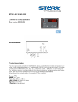
3.4 Top label
The illustration shows an example of a top label
affixed to an ERC 102D. The examples show what
is connected:
• Output 1 is used to switch the compressor
on and off.
• Outputs 2 and 3 are power – Live and Neutral.
• Output 4 is used to switch the heater on and off.
• Output 5 is used to switch the fan on and off.
• Output 6 is used to switch the light on and off.
• Input D (S1) is connected to a Cabinet Sensor to
measure temperature inside the cabinet.
• Input C(di) is used for Communications – a docking
station or KoolProg software running on a PC.
• Input B(S2) is connected to an Evaporator
Temperature Sensor.
• Input A(S3) is connected to an Ambient Light Sensor.
NOTE: Parameters depend on the code number sup-
plied. Please refer to the code number
specific technical drawing or use the KoolProg infor-
mation menu. For other applications,
a condenser sensor and a door sensor may
be used.
3.3 Connector outputs
All four outputs (
c
) are digitally controlled
on/off relays.
Functions controlled are:
• Compressor
• Pilot Relay
• Heater
• Defrost heater / valve for hot gas
• Alarm
• Fan
• Light
ERC 102 Reference manual – 3 OVERVIEW OF THE PRODUCT
C

10
There are three options for mounting the ERC 102
in a freezer or refrigerator.
SAFETY INFO
Risk of electrocution!
For mounting: Do not connect mains power until
the controller is correctly mounted.
For unmounting: Disconnect the power supply
before unmounting.
4. MOUNTING
1. Insert the ERC 102 into the cabinet.
2. Attach the clips to each side of the ERC 102.
3. Place the front frame on to the ERC 102 and click
it into place.
4. Connect the sensors and outputs as required and
then the power cable (see Chapter 6 – parameters
for information about programming which inputs
and outputs are applicable to your configuration).
4.1 Rear mounting – Option 1
ERC 102 Reference manual – 4 MOUNTING

11
4.1.1 Unmounting
1. Disconnect the power cable and then the sensors.
2. Use a flat head screwdriver (ideally the one
supplied with the ERC 102 sample package)
and insert it carefully between the front frame
and the controller.
3. Gently twist the screwdriver to remove the
front frame.
Do this in four places next to each
clip area.
5. Reach around the side to the clips.
ERC 102 Reference manual – 4 MOUNTING

12
6. Press the centre section of each clip to release
them in turn. Push the controller carefully out
of the cabinet.
1. Connect all the cables as required (see Chapter 6
– parameters for information about programming
which inputs and outputs are applicable to your
configuration).
2. Insert the ERC 102 into place in the cabinet.
3. Press the front frame into place – this locks the
ERC 102 into position.
NOTE: there is no need to use the clips for
front mounting.
4.2 Front mounting – Option 2
ERC 102 Reference manual – 4 MOUNTING

13
1. Use a flat head screwdriver (ideally the
one supplied with the ERC 102 sample package)
and insert it carefully between the front frame
and the controller.
3. Cabinet. Do not use a different type of
screwdriver or a sharp item such as a knife
which risks causing damage.
4.2.1 Unmounting
4.3 Fully integrated design – Option 3
An option is available for OEMs wanting to use the ERC
102 in a fully-integrated design. Please contact your
local Danfoss representative for more information.
2. Gently twist the screwdriver to remove the
front frame. Do this in four places next to each
clip area.
ERC 102 Reference manual – 4 MOUNTING

14
The ERC 102 can be controlled in three ways:
using KoolProg software, the Danfoss Docking
Station or manually by means of the buttons
on the front panel.
5.1 KoolProg/Gateway
KoolProg is licenced Danfoss software offering easy
parameter setup via a USB gateway. This software
is supplied separately; for technical literature and
further information, please contact your local
Danfoss representative.
5.2 Docking station
The ERC 102 controller docking station is supplied
separately. For further information, please contact
your local Danfoss representative.
5.3 Manual operation with buttons
(Direct Access)
Explained as follows:
5.3.1 ERC Front and Button Functionallity
5. CONTROLLING / NAVIGATION AND ACCESS LEVELS
1 Press: Variable direct function, e.g.ECO/Night mode
Sub function: Back
1 Press: Variable direct function, e.g. light
Sub function: OK
1 Press: Temperature setpoint
Sub function: Up
1 Press: Temperature setpoint
Sub function: Down
Danfoss ERC 102
Hold 3 sec: Menu
1 Click: Variable direct function, e.g.ECO/Night mode
1 Click: Variable direct function, e.g. light
Sub function: Up
1 Click: Temperature setpoint
Sub function: Down
Sub function: Back
Sub function: OK
ERC Front and Button Functionallity:
1 Click: Temperature setpoint
ERC 102 Reference manual – 5 CONTROLLING / NAVIGATION AND ACCESS LEVELS

15
5.3.2 Direct functions for access
Changing the Desired Temperature Setpoint (applies similarly when using Fahrenheit scale):
After 30 seconds, the display automatically
reverts to showing the current temperature
The display shows the current
temperature.
(Current temperature)
(Flashing: temperature setpoint)
(Flashing: temperature setpoint)
Press: up/down to adjust setpoint
1.)
2.)
3.)
4.)
Turning On/Off the ECO Function:
1.)
2.)
Press briefly
to enter
ECO mode
The green ECO symbol
is lit when in ECO mode
Danfoss ERC 102
Hold 3 sec: Menu
1 Click: Variable direct function, e.g.ECO/Night mode
1 Click: Variable direct function, e.g. light
Sub function: Up
1 Click: Temperature setpoint
Sub function: Down
Sub function: Back
Sub function: OK
ERC Front and Button Functionallity:
1 Click: Temperature setpoint
ECO
˚C
ERC 102 Reference manual – 5 CONTROLLING / NAVIGATION AND ACCESS LEVELS
Danfoss ERC 102
Hold 3 sec: Menu
1 Click: Variable direct function, e.g.ECO/Night mode
1 Click: Variable direct function, e.g. light
Sub function: Up
1 Click: Temperature setpoint
Sub function: Down
Sub function: Back
Sub function: OK
ERC Front and Button Functionallity:
1 Click: Temperature setpoint

16
Turn ON/Off the Light
Acknowledging Alarms:
5.3.3 Operating the menu
Button assignments in this manual refer
to the Glass Door Merchandiser default ERC 102.
For customised controls you may assign different
shortcuts (ASI menu --> button configuration).
Use this feature only when the ERC 102 is supplied
without button prints.
INFO: Some parameters may be hidden to you.
When scrolling through menus, the parameters
available will have been pre-determined using
KoolProg software. Your access level will determine
which parameters you can view and edit.
To turn off the Light
Press the light button again
Press any button to acknowlege
Flashing
Press the
Light button
briefly
1.)
1.)
2.)
Danfoss ERC 102
Hold 3 sec: Menu
1 Click: Variable direct function, e.g.ECO/Night mode
1 Click: Variable direct function, e.g. light
Sub function: Up
1 Click: Temperature setpoint
Sub function: Down
Sub function: Back
Sub function: OK
ERC Front and Button Functionallity:
1 Click: Temperature setpoint
ERC 102 Reference manual – 5 CONTROLLING / NAVIGATION AND ACCESS LEVELS

17
Danfoss ERC 102
Hold 3 sec: Menu
1 Click: Variable direct function, e.g.ECO/Night mode
1 Click: Variable direct function, e.g. light
Sub function: Up
1 Click: Temperature setpoint
Sub function: Down
Sub function: Back
Sub function: OK
ERC Front and Button Functionallity:
1 Click: Temperature setpoint
1.)
2.)
4.)
3.)
5.)
6.)
7.)
8.)
9.)
To select: press the lower left button (OK)
To confirm: press the lower left button (OK)
Press: OK to accept
and return to parameter name
Press: upper left button (back)
to return to parameter group
Press: upper left button (back)
to return to the menu
Example of Changing a Parameter:
Press and hold for 5 seconds to enter the menu
Press: up/down to scroll
through the menu
Press: up/down to find
the desired parameter
Press: up/down to enter
the desired value
(scroll through parameter groups)
(scroll through group “dEf” parameters)
ERC 102 Reference manual – 5 CONTROLLING / NAVIGATION AND ACCESS LEVELS

18
Danfoss ERC 102
Hold 3 sec: Menu
1 Click: Variable direct function, e.g.ECO/Night mode
1 Click: Variable direct function, e.g. light
Sub function: Up
1 Click: Temperature setpoint
Sub function: Down
Sub function: Back
Sub function: OK
ERC Front and Button Functionallity:
1 Click: Temperature setpoint
Press and hold 5
sec to access the
menu
1. ) Parameter groups
Lower left button
Lower left button
2.) Parameter names
(scroll through parameters)
(scroll through menu group)
3.) Parameter value
Danfoss ERC 102
Hold 3 sec: Menu
1 Click: Variable direct function, e.g.ECO/Night mode
1 Click: Variable direct function, e.g. light
Sub function: Up
1 Click: Temperature setpoint
Sub function: Down
Sub function: Back
Sub function: OK
ERC Front and Button Functionallity:
1 Click: Temperature setpoint
5.3.4 Menu structure
5.3.5 Password protection
Press and hold 5
sec to access the
menu
Password protection on three levels
Level 1: Shop (daily use by shop personnel)
Level 2: Ser (service technician)
Level 3: OEM (OEM programming)
ERC 102 Reference manual – 5 CONTROLLING / NAVIGATION AND ACCESS LEVELS

19
The ERC 102 inputs and outputs are configurable by
the customer. Before getting started it is a good idea
to check if all inputs are configured correctly and
match the sensors attached.
Input and output configuration settings are part of
the assignment menu (ASi).
NOTE: Coded sensors will impact on the number of
possible configurations.
For instance: Danfoss supplies only 2-pole defrost
sensors, so input S3 will most likely be used as a
defrost / evaporator temperature sensor input.
Please contact your local Danfoss representative for
information about default settings.
6. CONFIGURATION OF INPUTS AND OUTPUTS
6.1 Changing input and output configuration settings
Example: Input S1 is attached to a temperature sensor. The sensor measures cabinet temperature.
Example: Input S2 is attached a digital on/off sensor which is a door open / closed switch.
There are two steps to inputting the configuration:
1.
Define the type of sensor attached to the input:
- Temperature / light / digital
2. Define the application for the sensor:
- Temperature: control / condenser / evaporator
- Light: ECO / display / both
- Digital: door sensor
Danfoss ERC 102
Hold 3 sec: Menu
1 Click: Variable direct function, e.g.ECO/Night mode
1 Click: Variable direct function, e.g. light
Sub function: Up
1 Click: Temperature setpoint
Sub function: Down
Sub function: Back
Sub function: OK
ERC Front and Button Functionallity:
1 Click: Temperature setpoint
Assignments / ASi
Connector inputs: analogue (
a
), digital (
b
) Connector outputs (
c
)
ERC 102 Reference manual – 6 CONFIGURATION OF INPUTS AND OUTPUTS
C
b
a
S1 S2 S3

20
ERC menu
code
Default Min Max Unit Conv Unit Scale Default Access
Shop Ser OEM
Assignments ASi
S1 Config S1C Stn Stn dig no -- -- RW
S2 Config S2C Stn Stn dig no -- -- RW
S3 Config S3C Stn Stn dig no -- -- RW
S1 Application S1A SCo nC doo no -- -- RW
S2 Application S2A nC nC doo no -- -- RW
S3 Application S3A nC nC doo no -- -- RW
DI Config diC dio doC dio no -- -- RW
DO1 Config 01C CoP CoP HEt no -- -- RW
DO2 Config o2C dEF 0 Lig no -- -- RW
DO3 Config o3C FAn 0 Lig no -- -- RW
DO4 Config o4C dEF 0 Lig no -- -- RW
Button 1 Short Config b1C noP tP noP no -- -- RW
Button 1 Long Config b1L PoF tP PoF no -- -- RW
Button 2 Short Config b2C dEF tP noP no -- -- RW
Button 3 Short Config b3C tP tP noP no -- -- RW
Button 3 Long Config b3L ECo tP PoF no -- -- RW
Button 4 Short Config b4C
tn tP noP no -- -- RW
Button 4 Long Config b4L Lig tP PoF no -- -- RW
Password level1 PS1 0 0 999 no RW RW RW
Password level2 PS2 0 0 999 no -- -- RW
Password level3 PS3 0 0 999 no -- -- RW
Cabinet Light Control
Source
CLC Lig Lig LEC no -- -- RW
Light off delay Lod 0 0 300 no Sec 1 -- -- RW
ERC 102 Reference manual – 6 CONFIGURATION OF INPUTS AND OUTPUTS
/