Page is loading ...

Thank you for purchasing a Grandview projection screen.
Before use, please read instructions carefully. After installation, store instructions for future reference.
Model: SK-MIxx
Grandview Crystal Screen Canada Ltd.
#11- 3751 North Fraser Way,
Marine Way Business Centre,
Burnaby, BC, Canada V5J 5G4
Tel: 1-604-412-9777 Fax: 1-604-412-9796
Website: www.grandviewscreen.ca
Guangzhou Grandview Crystal Screen Co., Ltd.
No.43,Guomao Road South, Hualong Town,
Panyu District, Guangzhou City, China
Tel: +8620-8489-9499 Fax: +8620-8480-3343
Website: www.grandviewscreen.com
www.grandviewscreen.com.cn

1
by inappropriate installation or operation.
2. Please keep the screen away from hot sources, such as radiator, heating machine, fireplace,
loudspeaker or other relative device.
3. Only Plug with ground wire is acceptable.
4. Only accessories from authorized supplier is acceptable.
5. Please unplug the power wire when lighting and raining or not use with a long time.
6. Please handle the repair work to the professional agent.
7. Please prevent screen from water as well as putting stuff with water (such as vase) on the screen.
8. As soon as the plug of the screen is connected to the power source, the screen is connecting
with electricity.
9. Please use the approved power line (three-core power line)/ device interface/power plug.
10. Please use the rating (voltage, amps) power line (three-core power line) / device interface/power
plug. If have any questions about power line/ device interface/power plug, please contact the
professional people.
11. After installation, please locate a power device in order to disconnect power or connect the power
plug to electrical socket. This electrical socket should be installed to a convenient position. If the
accident occurs during operation, please disconnect power or take out the power plug.
12. The ceiling or wall used for fixture installation must be secure enough; load-bearing requirement
must be 4 times of the screen to prevent the screens from falling.
1. Please read carefully with this instructions before installation to avoid damage to product causing
Caution
Please notice the non-insulated voltage of the
spare parts to prevent from electric dangerous.
Please operate according to the user manual
with the screen.
Warnings
Warnings: Please prevent screen from wet place to avoid electric or fire dangerous.
To prevent from electric
dangerous, please don't
remove the end cap. There
is no need for users to
check the parts inside,
please handle the problems
to professional repairman.

Fabrics of Grandview motorized screen can be used for years, most problems are cost by simple incidents.
If problem occurs, please find the list below for some common solutions. If problems keep on, please contact
authorized agent of Grandview or call service number: (8620)34806166
1. Can not be used after installation completely.
Reasons
Solutions
2. The casing can drop, but can not rise.
Please check about the batteries as instruction manual.
Please connect the power line as instruction manual.
Return the sling wheel by hands.
Secure Positioning Executive Piece is blocked
Return the Secure Positioning Executive Piece by hands
Questions & Answers
Sling Wire
Brake Mechanism
Brake MechanismCable
Casing
No power or wrong installation of batteries in controller.
Power line disconnection
Sling Wheel is blocked
Reasons
Solutions
2
1. Safety
a. Please ensure whether the operating voltage is the same as local voltage. If the voltage adapter is required,
please contact the professional agent.
b. If any liquid or solid fall into the casing, please disconnect power and contact the professional agent.
c. If the screen is not being used for an extended period of time, please disconnect electricity.
d. Take out the power plug by hand.
e. Wall power socket needs to be installed at a convenient position.
f. As soon as the plug of the screen is connected to the power source, the screen is connecting with electricity.
g. Do not put the hands into casing.
2. Lighting
a. Do not stay the screen under lighting or sunlight to achieve the best viewing image.
b. Recommend using spotlight in viewing process, and magnesium light is not recommended.
c. The windows facing to screen need to be blocked by opaque curtain.
d. Using the screen in the room without reflective materials.
3. Cleaning and Maintenance
After cleaning, please disconnect power.
(1). Casing Clean
a.Please use the soft dry-cloth to clean the casing. Please remove the stubborn stains with Neutral detergent,
and then use the soft-cloth to clean.
b.The excess using of rubber or vinyl resin products will damage the appearance of casing.
(2). Fabric Clean
a.The damages of appearance of screen will influence the viewing image, please note the following:
1 Do not touch the screen by hands.
2 Please do not mark the screen surface
3 Do not shave the screen by finger or edge tool to avoid the crack or scratch.
4 Do not clean the screen with alcohol, benzene or thinner.
b. Retract the screen after using.
c. Please retract the screen without any insects, dust and foreign bodies.
Caution

16
Caution Illustration
The surface of screen is processed to achieve good performance of the reflector. Any damage of
surface will influence projection effects so please use this product in right way.
Caution
Please do not shake the screen by hand.
Please do not make any marks on screen
surface.
Prohibited
Prohibited
Please do not use any cloth with water, volatile oil and
corrosive cleaning agents to clean the screen, because
they will make the surface metamorphism and paint off.
Please do not pull the screen strongly that it will cause
the risk of damage.
Any stains on the casing, please use dry-cloth to
clean softly. If too serious, please use soft-cloth
with water-diluted neutral detergent to clean.
Neutral
Detergent
Please use a brush to clean the dust of screen surface
softly.
Please keep the screen far away from sunshine,dust and wet. Avoid using the screen in strong wind.
Tips
The surface of screen is dried
before shipment; if have any
strong smell, please open the
windows.
Maintenance
Location Caution
Please contact your local dealer for repairing and
replacing. Please contact us if you have any questions.
Avoid taking apart the fixture yourself.
Prohibited
Taking Apart
Caution
Prohibited
Prohibited
3
Description
Front View
Side View
Top View
Cable Box
1
2
3
4
5
6
8
9
10
11
12
Hook
Sling Wire
Casing
Secure Positioning Piece
Screen Fabric
Black Border
Retracting Limitation
SkyShow series is a perfect solution for installation in venues with high ceiling or
pillarsthat range from 5m to 8m。
15
16
Brake Mechanism
Skyshow Series Model B Skyshow Series Model A
17
18
Extending Limitation
Low Bar
Cable Box Plug
Socket
Positioning Screw
Carriage Wheel
Hanging Piece for Brake Mechanism (seriesB)
Hanging Hook for Brake Mechanism (series A)
Secure Positioning Executive Piece
Cable Box Socket
Buckle
Central Control Interface
LED
Front View
Side View
Accessaries
Screen parts
Front View
Side View
7
13
14
19
20
Flat Network Control
Cable Lock (1pc)
M5x10mm Screw(2pcs)

15
W
H
B1
B1
80
B3
253
167
4:3
150 "
180"
200"
240"
1 05 "
3048
3620
4020
4878
3320
2286
2715
3015
3660
1867
3405
3977
4377
5235
3677
1 0 8 "
3984
2240
4341
80
80
80
80
80
80
SK-M150
SK-M180
SK-M200
SK-M240
SK-M150
SK-M180
2819
3248
3548
4193
2400
2773
167
200
200
200
200
200
200
16:9
W (mm) H (mm)
B1(mm) B3(mm)
Format Model
Size(in)
Viewing area
L (mm) A (mm)
Net weight
(Kg)
Model A Series Data
Remarks: length will change upon different screen sizes, above specifications are subject to change without
informing. (The tolerance for L is 3mm.)
Casing
L length
Side view
A Fabric total length
Top view
Front view
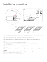
Take out all the parts from the packaging and follow the accessories guideline to ensure you have all parts,
and then follow the operations to install (Please follow model B series installation, which is the same as model A).
1.Fix the rings (not accessories) on the ceiling according the distance P1 between two hooks (note: make sure
each of rings can endure at least 100Kg to avoid falling down) (figure 1).
2.Fix the rings (not accessories) on the ceiling according the distance P2 between two hanging pieces of brake
mechanism (note: make sure each of rings can endure at least 200Kg to avoid falling down) (figure 2).
Multimedia Cable Box
Ceiling Installation Part
P
P2
P=L-188mm
P2=L-340mm

14
Specification
Model B Series Data
W (mm) H (mm)
W
H
B1
B1
50
B3
133
1:1
60 "
70 "
84 "
96 "
100"
1520
1780
2030
2338
2540
1520
1780
2030
2338
2540
1767
2030
2327
2635
2837
4:3
100 "
120 "
150"
2030
2338
3048
1520
1755
2286
2327
2635
3345
16:9
77 "
80 "
92 "
100 "
106 "
120 "
136"
1710
1771
2030
2214
2338
2656
3048
958
996
1145
1245
1320
1494
1715
2007
2068
2327
2511
2635
2953
3345
B1(mm) B3(mm)
25
23
50
50
50
50
50
50
50
50
50
50
50
50
50
SK-M60
SK-M70
SK-M84
SK-M96
SK-M100
SK-M100
SK-M120
SK-M150
SK-M77
SK-M80
SK-M92
SK-M100
SK-M106
SK-M120
SK-M136
1970
2230
2480
2788
2990
1970
2205
2736
1408
1446
1595
1695
1770
1944
2165
173
133
L Casing length
Side view
A Fabric total length
Top view
Front view
Remarks: length will change upon different screen sizes, above specifications are subject to change without
informing. (The tolerance for L is 3mm.)
Casing
Format Model
Size(in)
Viewing area
L (mm) A (mm)
Net weight
(Kg)
24.7
29.0
33.5
38.8
42.9
34.3
38.7
50.2
28.1
29.1
33.4
36.3
38.3
43.7
50.1 200
200
200
200
200
200
200
200
200
200
200
200
200
200
200
5
4. Hook the buckles of brake mechanism on the rings, and then fasten the buckles (figure 5-6)
Figure 5 Figure 6
Ring
Ring
Buckle
Hook
Brake Mechanism
Casing
Buckle
Brake
Mechanism
Buckle
Brake Mechanism
Hanging Piece
Buckle
Figure 7 Figure 8
5. Hook the low buckles of brake mechanism on the hanging pieces, and then fasten the buckles (figure 7-8)
Figure 9
Casing
Casing
Brake
Mechanism
Brake Mechanism
Hanging Piece
Casing
Brake Mechanism
Hanging Piece
Buckle
Brake
Mechanism
3.To hang the hooks on the rings (note: do not operate after pull out the cable from cable box) (figure 3-4).
Figure 3 Figure 4
Ring
Ceiling
Hook
Hook
Sling Wire
Casing

Uppper/Lower
Adjustment slot
5. Screen Adjustment
Don't roll out and retract the screen continuously over 4
minutes in a time to avoid overheating. If the motor overheats ,
keep 30 minutes for heat elimination .No lubrication using for
the motor, the drop and retract limit of the screen has been
preposition to an optimal configuration before delivery ,In order
to avoid motor damage ,please ask the local dealer or professional
for consultation when a new position setting is needed .
Motor Positioning
Screen Retracting adjustment
Only for your information: turn off the positioning switch.
(Note: the adjustment is extremely dangerous, please ask our technician for assistance without fail to
prevent destroying the screen or guarantee invalidation.)
The Note strongly suggests users not adjust the retraction limit privately; all the screens are preset before
delivery which satisfies most of the users' demand.
Description as follow is only restricted to few situations:
(1)Insert the adjuster in the adjusting slot (in the place where is nearest to the rear of the screen), when the
screen fabric is retracted to the casing, adjust the motor anchor point. The screen can be positioned at
where 40mm away from the casing if turning the adjuster for a circle deasil.
Note: Only when pressing DOWN button and operating for few seconds, that you can observe the
differences after position adjustment distinctly; then press UP button you can easily see the
difference of the position of the screen.
To avoid damage, please do not operate the screen before the first step.
(2)Turn the Motor Adjusting Slot anticlockwise for one circle, the screen will be positioned at where 40mm
away from the casing.
" "
" "
" "
" "
" "
" "
" "
Screen Extending adjustment
Adjust after the screen fabric is dropping completely:
(1) To adjust the position of the viewing area when the screen is falling down, first of all please insert the
adjuster in the slot, the viewing area will rise up about 40mm if turning the adjuster for a circle anticlockwise.
Note: Only when pressing UP button and operating for few seconds, that you can observe the
differences after position adjustment distinctly; then press DOWN button you can easily see
the difference of the position of the screen.
(2) If over-adjusting, anticlockwise adjustment can regulate the screen retraction. Adjustment is only after the
screen is completely dropped and up or down control is not in use.
Please operate carefully to avoid motor and screen damage by over-retraction .
Please operate carefully to avoid motor and screen damage by over-retraction.
1. Multimedia cable box; 5M automatic retracting.
Only use for the products which have this joint and the products
can work with the multimedia cable to connect computer or central
control. And they can be controlled by RS-232, RS-485 and trigger.
2. Synchro Power Relay
Connect the projector with Synchro Power Relay, and then the screen can be controlled by projector.
projector mount
Ceiling
Installation Strap
Projector
Synchro Power Relay
Power Source Output
Power Source Input
P
rogr
am
m
in
g
B
u
tt
o
n
Indicator Light
Installation Strap
Power Adjustment Button
Multimedia Cable Box
Optional
6. Drill 4 holes on the ceiling, and then select 5x40mm tapping screws to fasten the cable box on the ceiling.
(Recommendation: cable box must be installed above the power input of screen) (figure 10-11).
Figure 10 Figure 11
Ceiling
Tapping Screw
Cable Box
7. The screen includes two parts of cable; there are cable box and main cable. Firstly, please insert the plug
into socket (figure 12-13).
Figure 12 Figure 13
Power Line
9. Insert the plug from main cable into the socket on the cable box (figure 15-16).
Figure 16
Secure
Positioning
Piece
Socket
Casing
Secure
Positioning
Piece
8. Loop the cable with cable lock, and then fasten it onto the casing top via screw(note: separate the
cable and power to avoid the damages of power line).
4x10mm
Figure 14
Cable Lock
Power Line
Socket
Main Power Line Plug
Ceiling
Socket
613

12
(3). Upper Limitation Secure Positioning
For the safety, there is also Secure Positioning Piece besides the Remote Localizer.
a. Casing upper limitation uses the touching switch, consists of secure positioning piece system. (Refer to
description).You just need to loose the screw on the position piece and then fasten again after moving it to
the desired position (figure 30).
Figure 30
Sling Wire
Secure Positioning
Piece
b. When the casing retracts to a certain height and reach the secure positioning piece, the touching switch
would be off by being pressed by secure positioning piece onto the secure positioning executive piece .
The casing will not rise any more but can only lower down. ( Recommendation: cable box must be installed
above the power input of screen) (figure 10-11).
Casing
Figure 31 Figure 32
Secure
Positioning
Piece
Secure Positioning
Executive Piec
Remark: the position of positioning piece needs to be set according to the screen of electric positioning at
highest upper limitation.
Casing
Secure Positioning
Executive Piec
Secure
Positioning
Piece
The screen can be installed on the ceiling, with the reference to the above-mentioned steps 1-9 (figure 17).
Recessed Mount Illustration
Figure 17
Recessed Mount
Multimedia Cable Box
"DOWN for strap".
"UP for strap".
UP for screen fabric
STOP for both
DOWN for screen fabric
DOWN for strapUP for strap
7
c.To press the localizer hole at the back of the remote controller with one small pin or equivalence for about 3
seconds and then release, then press Down button for sling wire to the desired position and stop, the
screen is already reset for its extend limit (figure 28-29).
" "
Figure 28 Figure 29
Notice: for ensuring the security of positioning function, the distance between the upper limitation and secure
positioning mechanism must be 10cm. The effective setting period of electric positioning should be 60 seconds,
after 60 seconds will return to normal situation. If the setting fails within 60 seconds, please repeat as following
step: to press the setting button, then LED light will turn off; press the setting button again, then LED light will
turn on. In this movement, the resetting function will begin.

11 8
a.Upper limitation adjusting. Take off the knob from the hole and use the provided allen key to adjust (figure 24).
A clockwise adjustment will retract the screen (The distance between the screen and installation position will
decrease) and a counter-clockwise adjustment will extend the screen (The distance between the screen and
installation position will increase).
b.Lower limitation adjusting. Take off the knob from the hole and use the provided allen key to adjust (figure 25).
A clockwise adjustment will extend the screen (The distance between the screen and installation position will
increase) and a counter-clockwise adjustment will retract the screen (. The distance between the screen and
installation position will decrease).
Figure 24 Figure 25
Upper limitation Hole
Casing
Lower limitation Hole
Sling Wire
Sling Wire
Allen Key
a.When the screen is at loading situation, you can adjust the upper/lower limitation via the remote controller.
(Retract position is larger than 30cm to the installation position, extend position is smaller than 495cm
installation position).
b.To press the localizer hole at the back of the remote controller with one small pin or equivalence for about 3
seconds and then release, then press Up button for sling wire to the desired position and stop, the screen
is already reset for its retract limit (figure 26-27).
" "
Figure 26 Figure 27
Remark: default setting should be kept. If it is special solution, the remote localizer is recommended.
Casing
Allen Key
There are totally 3 solutions to position the screen, upper/lower limitation hole for sling wires, remote localizer
and position piece.
Upper limitation and lower limitation are set from factory, the upper limitation should be at 30cm which is the
distance between the screen and installation position (figure 22), and the lower limitation should be at 495cm
which is the distance between the screen and installation position (figure 23) (upper/lower limitation hole for
sling wires must be regulated by professional or dealers, please do not regulate yourself. Improper regulation
will cause the risk of damages).
30cm
495cm
Figure 22 Figure 23
Casing
Casing
Ceiling Ceiling
STOP for screen fabric
DOWN for strap
UP for strap
DOWN for screen fabric
UP for screen fabric
Common
Multi-function
Control Diagram
Red LED
Sling wires
localizer
battery
battery
Back view
Cautions:
1.The minimum distance between Controller and Receiver: 50cm
2.Workable within 8m in horizontal directionfrom the Receiver to the
Controller
3.Do not cover the Controller’s launching port while operation
4.Strictly banoperation in wet or high temperature environment.
5.Replacing batteries when the signal is faint or no signal.
6.Batteries for the Controller: 2 units CR2032 button cells.
Batteries Installation Instruction:
When the signal of the Controller is faint, please replace the batteries
as follow steps:
1.Reverse Contr
oller to the back, push down as the arrow mark to open
the cover.
2.Installtwo cells of battery and set the direction of positive and
negative electrode just like the chart shows.
3.Close the battery cover.
LED Indication Light
Under the casing on the left side, the LED light can indicate the
status of the screen.
When the light is on, it means the power supply is normal.
When the light is blinking, it means the screen is receiving signals.
LED
On: Normal
Blinking: Receiving Signal
Directive for lowering the screen
Directive for retracting the casing
Directive for lowering the casing

9 10
There is a load mechanism in the screen, assuring screen to work only after being properly installed. When
hanging the screen on the rings, screen gravity would turn the wheel via sling wires, which connects the load
switch automatically (figure 18-19).
Carriage
Wheel
There is matching function between controller and screen, and then controller needs to be programmed
before using.
(1). The screen is at situation of load. After connecting the power within 5 seconds, please press UP button
and STOP button simultaneously for 5 seconds then release.
(2). Press the DOWN button to ensure whether the programming works?
(3). If the programming fails, please repeat step 2 and 3.
" "
" "
"
Figure 18 Figure 19
Figure 20 Figure 21
2. Load Mechanism
3. Remote Controller Instruction
Casing
Carriage
Wheel
/