Page is loading ...

Nortec
MES2
Installation and
Operation Manual
Includes installation, operation
maintenance and troubleshooting
information for the Nortec MES2
Electrode Steam humidifier
2554140-D| 30 MAR 2019
Important:
Read and save these instructions. This guide to be left with equipment.

Thank you for choosing Condair.
Proprietary Notice
This document and the information disclosed herein are proprietary data of Condair LTD. Neither this
document nor the information contained herein shall be reproduced, used, or disclosed to others without the
written authorization of Condair LTD., except to the extent required for installation or maintenance of
recipient’s equipment. All references to the Condair name should be taken as referring to Condair LTD.
Liability Notice
Condair does not accept any liability for installations of humidity equipment installed by unqualified personnel
or the use of parts/components/equipment that are not authorized or approved by Condair.
Copyright Notice
Copyright 2019, Condair LTD. All rights reserved.
INSTALLATION DATE (MM/DD/YYYY)
MODEL #
SERIAL #
CYLINDER #

Contents
1 Introduction
2 Receiving and Unpacking
3 Nortec MES2 Models
6 Options and Accessories
7 Humidifier Components
9 Humidifier Schematic
9 How the Humidifier Works
11 Installation
12 Typical Nortec MES2 Installation
13 Location
14 Mounting
15 Plumbing
16 Steam Lines and Condensate
Returns
19 Primary Voltage Wiring
20 Control Wiring
21 Modbus Wiring
22 Nortec MES2 Installation Checklist
23 Operation
24 User Interface
25 Humidifier Configuration
27 Modbus Configuration
30 Start Up Procedure
31 Maintenance and
Servicing
32 Required Maintenance
36 Extended Shutdown
37 Maintenance Checklist
39 Troubleshooting
41 General Troubleshooting
43 Nortec MES2 Faults
45 Wiring Diagram
46 Spare Parts
50 Warranty

1 | Introduction
Introduction
CAUTION: Servicing
• Disconnect main power before performing any servicing.
• The plumbing and electrical compartments contain high voltage components and
wiring. Access should be limited to authorized personnel only.
• During and following operation of the humidifier, the steam and components in
contact with the steam such as the steam lines, steam distributors, cylinders, and
condensate lines can become hot and can burn if touched.
• Condair does not accept any liability for improperly installed humidity equipment
or the use of parts/components/equipment that are not authorized or approved
by Condair.
CAUTION: Electrical
All electrical work should in accordance with the local electrical code in location
where the humidifier will finally be operated.
CAUTION: Plumbing
Drain water from humidifier can be very hot. Do not drain to public sink.
All plumbing work should be in accordance with local plumbing code in location
where the humidifier will finally be operated.
CAUTION: Installation
• Do not mount on hot surfaces
• Do not mount in area where freezing can occur
• Do not mount on vibrating surface
• The Nortec MES2 produces steam at atmospheric pressure. No devices which
could block steam output should be connected to the steam outlet.
• Steam lines must be installed so that no restriction can produce backpressure in
the humidifier.
• Regardless of selecting on/off or modulating control method, Condair humidifiers
must have a closed circuit across its on/off security loop control terminal to
operate. Condair highly recommends the use of a duct high limit humidistat and air
proving switch.

Introduction | 2
Receiving and Unpacking
1 Check packing slip to ensure ALL material has been delivered.
2 All material shortages are to be reported to Nortec within 48 hours from receipt of goods.
Condair assumes no responsibility for any material shortages beyond this period.
3 Inspect shipping boxes for damage and note damages on shipping waybill accordingly.
4 After unpacking, inspect equipment for damage and if damage is found, notify the shipper
promptly.
5 All Condair products are shipped on an FOB factory basis. Any and all damage, breakage
or loss claims are to be made directly to the shipping company.
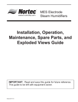
Before Installation
1 Ensure that available voltage and phase corresponds with humidifier voltage and phase as
indicated on humidifier’s specification label.
2 Ensure that the dedicated fused disconnect provided for the humidifier is of sufficient size to
handle the rated amps as indicated on the specification label.
3 Ensure sufficient clearances will be available as described in “Location” on page 13.
4 Ensure steam lines can be routed to distributor as described in Steam Lines and
Condensate Returns on page 16.
Figure 1: Specification Label Location

3 | Introduction
Nortec MES2 Models
The Nortec MES2 is the most advanced OEM steam humidifier available and provides steady
and reliable humidification using the same proven cylinder technology as Condair’s commercial
Condair's commercial electrode humidifiers. The Nortec MES2 is offered in 5 models
corresponding to control configurations as shown in Figure 2. The remote configurations
include 8 ft (2.4 m) of wiring for connecting the controls to the plumbing cabinet. The Primary
Voltage Wiring (PVW) model provides 8 feet of primary wiring for connection to the contactor.
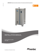
The Nortec MES2 is available in 6 capacities ranging from 5 to 30 lb/hr (2.3 to 13.6 kg/hr) for
operation on a range of voltages and phases as outlined in Table 1: Nortec MES2 Part Numbers and
Electrical Data. The 6 capacities are packaged in 4 different cabinet sizes as shown in Figure 3.
Figure 3: Nortec MES2 Capacities
and Cabinets
5 lb/hr
(2.3 kg/hr)
15 - 20 lb/hr
(6.8 - 9.1 kg/hr)
25 - 30 lb/hr
(11.4 - 13.6 kg/hr)
10 lb/hr
(4.5 kg/hr)
(REM CE)
Figure 2: Nortec MES2 Models
(ATT OE)
(ATT CE) (ATT CE PVW)
(REM OE)
RemoteAttached Attached PVW
N/A
O
p
e
n
E
l
e
c
t
r
i
c
al
C
l
o
s
e
d
E
l
e
c
t
r
i
c
al

Introduction | 4
Table 1: Nortec MES2 Part Numbers and Electrical Data
Capacity Phase Attached
Open
Elec.
Attached
Closed
Elec.
Remote
Open
Elec.
Remote
A
ttached
Closed
Elec. PVW
S
tandard
Cylinder
V
olts Amps
Max
Ext
Fuse
KW
Closed
Elec.
lb (kg) ATT OE ATT CE REM OE REM CE
ATT CE
PVW No. V A A KW
5 (2.3) 1 2550262
2550263
2550264
2550265
2550266
102 208 8.2
15
1.7
240 7.1
15
277 6.1
15
2550267
2550268
2550269
2550270
2550271
103 380 4.5
15
2550272
2550273
2550274
2550275
2550276
104 480 3.5
15
600 2.8
15
10 (4.5) 1 2550277
2550278
2550279
2550280
2550281
202 208 16
25
3.4
240 14
20
277 12
20
2550282
2550283
2550284
2550285
2550286
203 380 8.9
15
2550287 2550288 2550289
2550290
2550291
204 480 7.1
15
600 5.7
15
15 (6.8) 1 2550300
2550301
2550302
2550303
2550304
321 208 25
40
5.1
240 21
30
277 18
30
2550305 2550306 2550307
2550308
2550309
305 380 13
20
2550310
2550311
2550312
2550313
2550314
309 480 11
15
600 8.5
15
3 2550315
2550316
2550317
2550318
2550319
303 208 14
20
240 12
20
2550320
2550321
2550322
2550323
2550324
311 380 7.7
15
2550325
2550326
2550327
2550328
2550329
311 480 6.1
15
600 4.9
15
20 (9.1) 1 2550340
2550341
2550342
2550343
2550344
321 208 33
50
6.8
240 28
45
277 25
35
2550345
2550346
2550347
2550348
2550349
305 380 18
30
2550350
2550351
2550352
2550353
2550354
309 480 14
25
600 11
20
3 2550355
2550356
2550357
2550358
2550359
303 208 19
30
240 16
25
2550360
2550361
2550362
2550363
2550364
311 380 10
15
2550365
2550366
2550367
2550368
2550369
311 480 8.2
15
600 6.5
15
25 (11.4) 3 2553765
2553766
2553767
2553768
2553769
421 208 24
35
8.5
240 20
30
2553770
2553771
2553772
2553773
2553774
407 380 13
20
2553775
2553776
2553777
2553778
2553779
411 480 10
15
600 8.2
15
30 (13.6) 3 2550370
2550371
2550372
2550373
2550374
421 208 28
40
10
240 25
40
2550375
2550376
2550377
2550378
2550379
407 380 16
25
2550380
2550381
2550382
2550383
2550384
411 480 12
20
600 9.8
15

5 | Introduction
Nortec MES2 Dimensions /
Weights
Note: Unless otherwise specified dimensions are in inches (cm). Tolerance ±0.1 in. (0.25 cm)
Capacity
lb/hr (kg/hr)
A
Width
B
Depth
C
Height
D*
Steam
Outlet
E*
Steam
Outlet
F
Elec.
Pos.
G
Elec.
Height
H
Drain
Center
J
Drain
Center
Net/Full
Weight**
lb (kg)
5
(2.3)
7.5
(19)
6.4
(16.3)
12.7
(35.3)
4.2
(10.7)
5.1
(13)
0.3
(0.8)
4.9
(12.5)
5.6
(14.2)
3.4
(8.6)
10.7/14.2
(5/6.6)
10
(4.5)
7.5
(19)
6.4
(16.3)
16.8
(42.7)
4.2
(10.7)
5.1
(13)
0.3
(0.8)
8.0
(20)
5.6
(14.2)
3.4
(8.6)
12.4/18.4
(5.8/8.5)
15-20
(6.8 – 9.1)
8.9
(22.6)
7.9
(20.1)
20.0
(50.8)
5.1
(13)
4.0
(10.2)
1.1
(2.8)
11.2
(28.5)
6.4
(16.3)
4.2
(10.7)
16.5/30.5
(7.8/14.2)
25-30
(11.4 – 13.6)
10.3
(26.2)
9.8
(24.9)
20.7
(52.6)
5.5
(14)
4.9
(12.5)
2.2
(5.6)
11.6
(29.5)
6.8
(17.3)
5.2
(13.2)
20.2/43.2
(9.5/20.0)
Note: * Steam Outlet is not centered on MES2 5 & 10 lb/hr (2.3 & 4.5 kg/hr) models.
** Weights given for Nortec MES2 with enclosed electronics and
optional plumbing enclosure. Full Weight is weight with cylinder full of
water. Full weight may exceed this value at end of cylinder life depending on the amount of scale and its
composition.
Figure 4: Nortec MES2 Dimensions and Weights
5.50
14
F
2.30
5.8
A
B
C
D
E
3.70
9.4
1. 7 3
4.4
G
7.79
19 . 8
1. 2 8
3.3
0.57
1. 4
2.5 (6.4) Nortec MES2 25 - 30
1.5 (3.8) Nortec MES 5 - 20
0.80
2
1.12 x 2.0 (2.85 x 5.1) Slot
Both Cabinet Sides
0.30
0.8
J
H
O
5.45
13 . 8
Rotate 360
v
to
Desired Position
0.875 (22 mm) O
S team Outlet
0.34 (9 mm)
Condensate
Re t u r n
1/ 8 NPT
Fill Connection
0.875 (22 mm)
O
Drain Outlet

Introduction | 6
Options and Accessories
An enclosed plumbing option is available for each Nortec MES2 cabinet size. The option
consists of a fixed cabinet with an easily removable door for servicing. Figure 5 shows the
enclosed plumbing option installed on a 10 lb/hr Nortec MES2 ATT CE.
Figure 5: Enclosed Plumbing Option
Condair also provides a complete line of options and accessories for every humidification
application. The following table lists some of the most common accessories available for use
with the Nortec MES2 humidifier. Refer to the installation instructions that come with the
accessories for their proper installation and operation.
Table 2: Options and Accessories
Option / Accessory Used For
Modbus Interface Controlling humidifier operation via Modbus (See Modbus Wiring
on page 21 and Modbus Configuration on page 27).
Enclosed Plumbing See above.
Steam Distributors Adding steam into air ducts.
On/Off or Modulating Control Humidistats Controlling the output of the humidifier based on sensed RH.
Air Proving Switch Insuring humidification only occurs when air is moving in a duct.
Steam Hose Connecting humidifier to steam distributor.
Condensate Hose Collecting and draining condensate that collects in steam
distributors and steam distribution lines.
Capacity Part No.
10 lb/hr (4.5 kg/hr)
15, 20 lb/hr (6.8, 9.1 kg/hr)
25, 30 lb/hr (11.4, 13.6 kg/hr)
Enclosed Plumbing Part Numbers
5 lb/hr (2.3 kg/hr)
2554073
2554074
2554075
2554076

7 | Introduction
Humidifier Components
Figure 6: Nortec MES2 Components
On/Off/Drain Switch
Control Board
Power Relay
Electrical Cover
Control Connection
Terminals
Ground Clam
p
Bracket, Remote
Electrical
Steam Outlet
Condensate Return
Fill Cup
Drain Valve
Drain Outlet
Drain Canal
Fill Valve
Cylinder
Cylinder Plug
High Water Sensor
Plug
Fill Inlet
Plumbing
Enclosure
(Optional)
Plumbing
Door
(Optional)
Cylinder
Tie Wrap
Drain Pan
Status Lights
Current Sensor
Capacity Adjustment
Potentiometer

Introduction | 8
Table 3: Nortec MES2 Components
Component Function of Component
Bracket, Remote
Electrical
Supports the control components for Nortec MES2 models which have
remote electronics (REM).
Capacity Adjustment
Potentiometer
Adjusts the maximum output of the humidifier from 100% down to 20%.
See Figure 22: Capacity Potentiometer Adjustment on page 26.
Condensate Return
Provides a connection to return condensate to humidifier.
Control Connection
Terminals
Terminals on the control board for connecting external controls to
humidifier.
Current Sensor
Measures the amount of current flowing through the cylinder’s
electrodes.
Cylinder
Holds electrodes in water. Current between electrodes generates heat
used to generate steam.
Cylinder Plug
Power connectors to electrodes in cylinder. Installer must connect wires
from contactor to cylinder plugs. (PVW model has wires installed).
Cylinder Tie Wrap
Holds cylinder in place, reusable.
Drain Outlet / Canal
Combines cylinder drain water and fill cup overflow into a single drain
outlet.
Drain Pan
Collects any water which may leak from water connections and routes it
to drain.
Drain Valve
Drains water from humidifier.
Control Board
Controls all functions of the humidifier’s operation and provides input
and output connections to humidifier components.
Electrical Cover
Covers the control board and wiring on Nortec MES2 models with
closed electrical (CE).
Fill Cup
Provides an air gap for backflow prevention.
Fill Inlet
1/8 NPT brass fitting for connecting supply water to the humidifier.
Fill Valve
Controls flow of water into humidifier.
Ground Clamp
Electrical ground connection for humidifier.
High Water sensor
Plug
Used to detect max water level in cylinder.
On/Off/Drain Switch
Turns power on/off to humidifier controller and drains the cylinder for
servicing. Note: Turn off humidifier disconnect to shut off primary power
to the humidifier.
Plumbing
Enclosure/ Door
The optional plumbing enclosure completely encloses the humidifiers
water components.
Power Relay
Turns on/off power to the contactor (supplied by others) based on a
signal from the humidifier’s controller (mounted on control board).
Status Lights
Indicate if the humidifier is operating. If the humidifier is shut down on a
fault the yellow LED flashes in sequence to indicate the fault that
occurred.
Steam Outlet
Outlet for steam generated by the humidifier. Connect to the outlet with
a steam hose and hose clamp.

9 | Introduction
Humidifier Schematic
Figure 7: Humidifier Schematic
How the Humidifier Works
The Nortec MES2 is an atmospheric steam generator that uses heat generated by electrical
current flowing between submerged electrodes to generate steam. The Nortec MES2 is
designed for air humidification via steam distributor.
Steam Generation
• If the Nortec MES2 is configured for On/Off operation then as soon as the safety loop
between terminal 1 and 2 is closed the humidifier assumes 100% demand, closes the power
relay on the control board, and measures the current fl
owing through the power wire routed
through the control board’s current sensor. If it is configured for modulating operation it waits
for a demand signal and for the safety loop between terminal 1 and 2 to be closed.
From
Contactor
To
Contactor
24 VAC
Power Relay
Control Board
Steam Distributo
r
Steam Line
Cylinder
Drain Canal
Fill Valve
Condensate Return
Fill Cup
Overflow
Electrodes
Internal Air
Gap
Air Gap
1.25 in.
(3.2 cm)
Drain Valve
External Air
Gap
Current Sensor
High
Water
Sensor

Introduction | 10
If the demand is lower than the actual output the inlet valve is kept closed and output is
reduced by letting the water level in the cylinder decrease by evaporation.
If demand is higher than the actual output after a brief delay the fill valve is activated and
water flows into the fill cup. Water from the fill cup flows into the bottom of the cylinder
through a hose connected to the drain valve housing.
Note: The cylinder is gravity fed from the fill cup. If backpressure from the steam line is too
high it will cause water to back up in the fill cup and flow down the overflow line to the
drain.
• A soon as the water in the cylin
der comes in contact with the energized electrodes current
flows thro
ugh the water. The resistance of the water to the electrical current generates heat
and in turn steam. The more electrode that is covered by water the higher is the current and
output. The unit continues to fill until the current matches demand or the high water sensor
detects a high water level.
• The Nortec MES2 repeats the fill and boil down cycle repeatedly to match output to demand.
• Over time minerals in the water will adhere to the cylinder’s electrodes. The humidifier will
automatically fill to a higher water level to maintain full capacity during the life of the cylinder.
Eventually because of scale formation it will no longer be possible for the humidifier to reach
its full capacity. The Nortec MES2 software monitors this condition and when detected will
stop operating and flash the yellow LED in a repeating sequence of 4 flashes.
Drains
• As steam is produced minerals are left behind increasing the conductivity of the water. The
Nortec MES2’s patented auto adaptive cycle will monitor the water conductivity and perform
drains to maintain the water at optimal conductivity for peak performance.
• The auto adaptive cycle provides the longest cylinder life in combination with keeping the
tightest control and most efficient use of water during the entire cylinder life.
Steam Distribution
The most common method for adding the steam into the air is to mount a steam distributor in a
supply air duct as shown in Figure 7: Humidifier Schematic. In an air handler the best location
for introducing the steam is after the heating coil where the air will be at its lowest humidity.
Steam Line
The steam line between the cylinder steam outlet and the distributor may be Condair steam
hose, copper pipe, or stainless steel pipe or tube. The Nortec MES2 is an atmospheric steam
generator so it is very important no restrictions are present in the steam line and that the steam
line is sized properly to carry the full output capacity of the humidifier. See Steam Lines and
Condensate Returns on page 16 for information on selecting steam lines.
Condensate Return
Whenever steam is generated, condensate is formed in the distribution system and steam
distributor. Insulating steam lines is one important way to reduce the amount of condensate
formed. Steam lines are sloped so that condensate does not collect in the lines and create a
restriction to steam flow. The condensate must be collected and removed from the system so
that it does not build up and leak into the duct or air handler. Condensate can be returned to
the MES2 fill cup to reduce water waste or can be fed to drain.

11 | Installation
Installation
12 Typical Nortec MES2 Installation
13 Location
14 Mounting
15 Plumbing
16 Steam Lines and Condensate Returns
19 Primary Voltage Wiring
20 Control Wiring
21 Modbus Wiring
22
Nortec MES2 Installation Checklist

Installation | 12
Typical Nortec MES2 Installation
* Dimensions and brackets are recommendations based on best practice. OEM must verify operation if they are not followed or used.
Figure 8: Typical Humidifier Installation
Control
Wiring
Pg 20
Plumbing
Pg 15
Primary
Voltage
Pg 19
1 ft (30 cm)
min. before
any bend*
12 in. (30 cm)
min. radius*
Condensate
trap
2 in. (5 cm)
min.
1 ft (30 cm)
Support
brackets*
Fuse
O
n
/
O
f
f
(
S
a
f
e
t
y
L
o
o
p
)
2
4
V
A
C
On/Of
f
Drain
Switch
2
4
V
A
C
C
o
n
t
a
c
t
o
r
E
n
e
r
g
i
z
e
Power Relay
L2
L1
Disconnect Contacto
r
Current transforme
r
Cylinde
r
plug with
white
marke
r
Note:
Single Phase
Connection Shown
0.875 in.
(22 mm).
OD
1/8 in.
NPT
A
ir gap
recom-
mended
Drain
7/8 in. Min.
Cold Potable Water
30 - 80 PSIG
Front side
clearance required
for cylinder removal.
36 in. (90 cm)
recommended
r
Fill
Line
Drain
Line
Steam Line
Steam
Distribution
Location
Mounting
Pg 13
Page 16-18

13 | Installation
Location
Mount to structural member or on surface capable of supporting the humidifier’s operating
weight (see Figure 4: Nortec MES2 Dimensions and Weights). The humidifier may be set on its
base but clearance must be provided for the drain line to be sloped adequately. In general
clearance is not required around the humidifier except for maintenance access and electrical
and plumbing connections.
The clearance dimensions shown are recommendations based on best practice. OEM must
verify operation if they are not followed.
Install only in areas with ambient temperature 41-104°F (5–40°C) relative humidity 5 -
95%.
When possible install below the steam distributor. If mounted above the steam distributor
take care to provide proper steam line routing and proper condensate traps.
DO NOT locate the humidifier any further then absolutely necessary from the steam
distributor location as net output will be reduced as a result of heat loss through the steam
line.
The main service access required is for changing the cylinder. This access can be from the
front or right side. Right side service access is not possible with the optional plumbing
enclosure.
* Dimensions are recommendations based on best practice. OEM must verify operation if they are not followed.
Figure 9: Mounting Location / Clearance
Note: Condair recommends a vertical drop from the drain outlet and an air gap as
close as possible to the drain outlet to insure proper draining of the humidifier.
36 in. (92 cm)*
side clearance
for right side
cylinder removal
only.
36 *
front clearance
for front cylinder
removal and/or for
attached electronics
models only.
in. (92 cm)
Mount level
As close as
possible to steam
distributor
5-95%
0.5 in. (1.3 cm)*
top clearance
access hole required
for steam outlet and
optional condensate
return to fill cup.
8 in. (20 cm)*
left side clearance
for removal of cover
on attached closed
electronics models
only.
0 in. (0 cm)
front clearance
for right side
cylinder removal
00
side clearance
for front cylinder
removal
in. ( cm)
Note:
side cylinder
removal not
possible with
enclosed
pluming option.
0 in. (0 cm)
access hole or
additional clearance
required for fill
connection
0 in (0 cm) bottom clearance.
Access for properly sloped drain required.
0.2 (0.5 cm)*
for fill cup
tabs.

Installation | 14
Mounting
1 The Nortec MES2 humidifier can be wall or floor mounted. No mounting holes are provided
but can be made anywhere in the base and sides of the cabinet at installation time.
2 Use a minimum of 2 x #8 screws mounted securely into structural surfaces.
3 Make sure the unit is level.
4 If enclosed plumbing option is installed then mounting screws can also be installed into the
plumbing enclosure.
5 It is the installer’s responsibility to insure that the humidifier is securely and safely mounted
in the air handler.
Figure 10: Nortec MES2 Mounting
Note:
Installation methods shown are suggestions only actual mounting may differ and must
be verified by OEM.
When mounting to a vertical member by drilling holes in the cabinet, be careful not to
make any holes in the bottom 1 in (2.5 cm) of the drain pan.
Nortec MES2
A
ttached Electronics
(Back Mounted)
Nortec MES2
Remote Electronics
(Side/Base Mounted)
Air Handler
Plumbing
Drill holes in back,
side, or base of cabinet
and secure with min. of
2 x #8 Screws.
Remote Electronics
Mount using 4 screws i
0.19 in. mounting holes
Avoid drilling in
bottom 1 in (2.5 cm)
of drain pan.

15 | Installation
Plumbing
Figure 11: Water Supply and Drain Connection
• All water supply and drain line connections should be installed in accordance with local
plumbing codes.
• Supply water is recommended at 30 to 80 PSIG and 150-1200 Microsiemens (Hardness
0-12 GPG). Consult factory for water conditions outside of this range. Install water shut off
valve before humidifier to facilitate servicing.
• The drain line should not end in a sink used frequently by personnel, or where plumbing
codes prohibit it. Route to a floor drain or equivalent for safety reasons.
• Ensure drain line is adequately sized to provide free and easy draining and that an air gap is
installed as shown. A restricted drain can cause cylinder water to over concentrate and
result in poor operation.
• If a drain is not located near the humidifier use a condensate pump rated for hot drain water
such as Condair’s P/N 1429527.
For humidifiers installed in some cities including the City of Los Angeles:
A city-approved spring-loaded double ball CHECK VALVE must be installed by
contractor on the potable water inlet to the humidifier. Recommended valve
manufacturer: Watts Regulator, Size 3/8” inlet and outlet, Model #7.
Each drain line from the humidifier must be routed, without dips or sags, to
terminate above the flood level rim of a city approved indirect waste receptor.
0.875 in. (22 mm). OD
un-threaded outlet
Always install a water
shut-off valve.
1/8 in. NPT
fill connection.
Air gap recommended.
1 1/2 in. to 7/8 in.
Copper reducer is ideal.
(Condair option P/N 2522172)
Hose must not touch the
bottom of the funnel.
Min. 7/8 in. OD drain line.
Ensure adequate slope to
handle flow.
Use 1/2 in. OD coppe
r
to within 4 ft (1.2 m) o
f
humidifie
r
*Elbows, pipe, water shut-off valve, and air gap reducer not supplied by Nortec.

Installation | 16
Steam Lines and Condensate Returns
Figure 12: Main Steam Line Requirements
Table 4: Recomme
nded Steam Line Material
Steam Line
Material
Steam Line Length
ft m Steam Line Description
Copper Tube 0-10 0-3 3/4 in MED-L Tubing (7/8 in. OD)
Stainless Steel
Tube
0-10 0-3
7/8 in. Tubing (0.049 W)
Nortec Hose < 10 < 3 Part Number 1328810 (7/8”)
Note: Larger diame
ter lines should be used for steam runs longer than those listed. Contact Condair for recommendation and
instructions on proper installation of reducers for larger diameter steam lines.
Table 5: Maximum Recommended Length of Steam Line
Steam Output
(Lb/hr)
Distance
(ft)
Possible Loss
(lb/hr)
Steam Line Size
(in)
5 8 1.0
3/4
10 15 1.5
3/4
1
15
20 2.0 3/4
1
20
25
25 2.5 3/4
1
30
NOTE: 1 Contact Condair for information on possible losses of other steam line diameters used for longer runs.
2 The use of steam line other then copper,
stainless steel tube or Condair supplied steam line will void the
warranty and may adversely affect the operation of the humidifier
S
t
e
a
m
D
i
r
e
c
t
i
o
n
S
t
e
a
m
D
i
r
e
c
t
i
o
n
S
t
e
a
m
D
i
r
e
c
t
i
o
n
2 in.
(5 cm)
1 ft (30 cm)
1ft (30 cm)
0.5 in.
(12 mm)
10 Degrees
2 Degrees
Use Appropriate Slope Insulate Pipe
1 in. (2.5 cm) pipe
insulation
MAIN RULES FOR ATMOSPHERIC STEAM LINES
Slope the steam lines
Trap condensate (Use full size ‘T’ for Traps)
Condensate traps must be a minimum of 3 in. (15 cm) in height or duct static
pressure + 2 in. whichever is greater.
Steam lines must not have any restrictions which could cause back pressure.
1.0 in. (2.5 cm) pipe insulation recommended.
Follow recommended materials, size and length see tables.

17 | Installation
Figure 13: Condensate Traps
* Dimensions and brackets are recommendations based on best practice. OEM must verify operation if they are not followed.
Figure 14: Steam Distributor Above Humidifier (Hose)
12 in. (30 cm)
min drop to
top of ‘P’ Trap
P Trap min
6 in. (15 cm)
or
duct static
pressure + 2 in
whichever is
greater
Tee is same size
as steam line
Use a full size tee, not a 90
degree elbow for vertical
to horizontal transitions.
‘P’ Traps Use:
- Condair 0.375 in condensate hose
- 1/4 in Med-L copper tubing, or
- 0.375 in stainless steel tubing
Condensate drains must be sloped down.
Route to humidifier fill cup if possible.
1 ft (30 cm)
before any
bend*
12 in.(30 cm)
min. radius*
Condensate
trap
Condensat
e
line
Connect steam
hose to cylinder
Connect condensate
hose to fill cup
or to drain.
2 in. (5 cm)
min.
1 ft (30 cm)
Support
brackets*
/