Page is loading ...

FGR 100
Owner’s Manual
Öhlins Front Fork Superbike

1
Introduction
It was the 1970’s, a young man named Kenth
Öhlin spent most of his spare time pursuing his
favourite sport: motocross.
A careful observer, Kenth’s attention
was continually drawn to one specic de-
tail - motocross bikes had more engine
power than their suspension could handle.
It was not long before Kenth realised that bet-
ter performance could be achieved by improved
wheel suspension.
Öhlins Racing was established in 1976, and just
two years later the company won its rst World
Championship title. Despite being in the business
for 30 years, the search for perfection and new
functions is still the main focus of the company.
Congratulations! You are now the owner of an
Öhlins Front Fork. More than two hundred World
Championships and other major world titles are
denitive proof that Öhlins products offer out-
standing performance and reliability.
Every product has gone through rigorous
testing and engineers have spent thousands of
hours, doing their very best to use every possi-
ble experience from our 30 years within the rac-
ing sport. The product that you now have in your
possession is pure racing breed that is built to
withstand.
By installing this front fork on your bike you
have made a clear statement… you are a serious
rider with a focus on getting the maximal han-
dling ability and outstanding feedback from your
bike. Along comes the fact that your front fork will
be a long lasting friend, delivering the very best
of comfort and performance every time you go
for a ride. Go explore!
2
Safety Precautions
© Öhlins Racing AB. All rights reserved. Any
reprinting or unauthorized use without the written
permission of Öhlins Racing AB is prohibited.
Printed in Sweden.
Safety Symbols
In this manual, mounting instructions and
other technical documents, important infor-
mation concerning safety is distinguished by
the following symbols:
The Safety Alert Symbol means: Warning!
Your safety is involved.
Warning!
The Warning Symbol means: Failure to
follow warning instructions can result in
severe or fatal injury to anyone working
with, inspecting or using the front fork, or
to bystanders.
Caution!
The Caution Symbol means: Special
precautions must be taken to avoid
damage to the front fork.
Note!
The Note Symbol indicates information that
is important regarding procedures.
Note!
The front fork is a very important part of the
vehicle and will affect the stability.
Read and make sure that you understand
the information in this manual and the
mounting instructions before you use this
product. If you have any questions regarding
installation or maintenance please contact an
Öhlins dealer.
Öhlins Racing AB can not be held
responsible for any damage to the front fork,
vehicle, other property or injury to persons, if
the instructions for installing and maintenance
are not followed exactly.
Warning!
This product was developed and designed
exclusively for a specic vehicle model and
shall only be installed on the intended vehicle
model in its original condition as delivered
from the vehicle manufacturer.
This product contains pressurized nitrogen
gas (N
2
). Do not open, service or modify this
product without proper education (authorized
Öhlins dealer/distributor) and proper tools.
After installing this product, take a test ride
at low speed to make sure that your vehicle
has maintained its stability.
If the suspension makes an abnormal
noise, or the function is irregular, or if you
notice any leakage from the product, please
stop the vehicle immediately and return the
product to an Öhlins Service Centre.
Note!
When working on this product, also read your
Vehicle Service Manual.
This Manual shall be considered a part of
the product and shall therefore accompany
the product throughout its life cycle.

3
Contents
Introduction 1
Safety Precautions 2
Contents 3
Öhlins Front Fork FGR100 4
Setting up your Front Fork 5
Technical Information 7
Workshop Section 9
Oil level 21
Troubleshooting 22
Spare Parts List 23

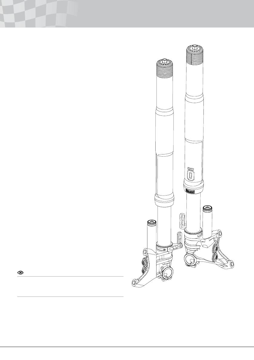
4
Öhlins Front Fork FGR 100
The product in your hand is an artwork, prepared
by our dedicated craftsmen at our Swedish facil-
ity in Upplands Väsby, Sweden. Its predecessors
have battled their way on numerous race tracks
in World Superbike, Supersport, Superstock and
AMA, and the legacy continues in your front fork.
Thousands of hours have been spent together
with some of the best teams in the world to nd
the optimal design and functionality to give you as
much performance as possible. You will feel the
difference…be sure.
The new, improved FGR 100 comes fully
packed with technical solutions and experiences
gained from MotoGP and WSB racing. Used by
Max Biaggi when he secured the WSB-title on an
Aprilia in 2010. Changes for 2011 include new
fork bottoms and a new stronger outer tube.
Design
The DNA of this new FGR 100 originates in the
most prestigious race series in the world and the
front fork is weight optimized as a result of that
fact. We have used exclusive racing components
from our R&D department to increase the perform-
ance of the front fork.
Our engineers that work on a daily basis with the
top riders in the world often hear the word “feel-
ing” and “control” when they debrief after tests and
races.
We wanted to pour as much of these impor-
tant factors into your front fork and as a result,
the FGR 100 gives you improved “brake support”
and “tire feel” when riding. For all of you that have
your mind set on doing some serious racing we
have some really good news.
The FGR 100 is the very essence of front fork
technology and is based on last year’s successful
predecessor FGR 000. This pressurized front
fork, equipped with 25mm TTX technology is the
very latest in front fork technology.
New features on the FGR 100
• New stronger outer tubes
• Length adjustable (+8mm)
• New fork bottoms with improved clamp
system
• New laser engraving on the fork leg
5
Setting up your Front Fork
Basic Guidelines
Note!
The front fork is just one part of your motorcycle.
To get it to work properly, set up your motorcycle
according to your vehicle service manual.
1
Put your motorcycle on a workstand and install the
Öhlins front fork according to your vehicle service
manual.
2
Check Ride Height
Note!
We recommend you to have an assistant for this
procedure.
The following procedure should be performed on
a at surface.
Note!
The lower triple clamp must not be tightened
to more than 12-15 Nm. This is also important
for the steering damper bracket, when located
around the upper front leg. Too high torque may
deform the front fork leg, affecting the function
negatively.
Note!
See Chapter “Technical Information” for technical
data for the FGR 100.
Note!
Install the front fork so that the splines are facing
out from the motorcycle.
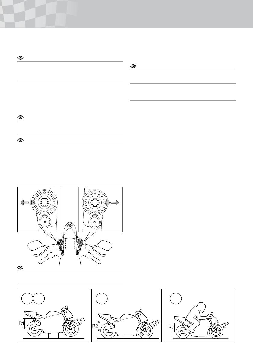
2.1
Put the motorcycle on a stand.
Make sure that the shock absorber is fully ex-
tended.
2.2
Measure the distance from a point marked by a
piece of tape, immediately above the rear wheel
axle, to the wheel axle (R1).
2.3
Make a similar measurement on the front axle,
for example, from the bottom of the upper tri-
ple clamp to a xed point, for example the front
wheel axle (F1). Make sure that the front fork is
fully extended.
2.4
Put the motorcycle on the ground so that the
front and the rear suspensions are slightly com-
pressed. Repeat the measuring procedures
(R2 and F2).
2.5
Sit on the motorcycle in normal riding position,
properly outtted in your riding gear. Correct
riding position is important so that the weight
is balanced on the front and rear wheel in the
same way as when riding. Repeat the measur-
ing procedure (R3, F3).
2.2 2.4 2.52.3

6
Setting up your Front Fork
Spring Preload Adjuster
Use a 14 mm wrench. Adjust the spring preload by
turning the nut on the top of the fork leg.
1 turn on the adjustment nut will change 1 mm in
spring preload.
Recommended static sag (F1-F2): 25-30 mm
14 mm wrench
Increase Preload
Reduce Preload
Rebound and Compression Adjusters
Turn the adjuster screw(s) at fork bottom. Use
tool 00794-01.
Recommended adjustment “clicks” from closed
position: See spec. card
Rebound Adjuster
Compression Adjuster
Tool 00794-01
Turn clockwise to close valve
Turn counter clockwise to open valve
Note!
The spring preload is very important since it
affects the height of the motorcycle and the fork
angle. Consequently, handling characteristics can
be changed, even negatively.
5
If the measures still differ, you may need to change
spring. Contact an Öhlins dealer for advice.
3
The measurements should not differ from the fol-
lowing:
Rear 30±5 mm (R1-R3)
Front 35±5 mm (F1-F3)
4
If the measures differ signicantly from the meas-
ures above, you need to set the spring preload.
Adjust Spring Preload, Rebound and Compression
7
Technical Information
FGR 100
Front fork length/stroke 740/130 mm
Optional length/stroke 748/130 mm
Optional length/stroke 748/138 mm
Free spring length 260 mm
Adjustment Range
Compression ~28 clicks
Rebound ~28 clicks
Spring preload 0-18 mm
(0-18 turns)
The adjustment range from closed valve (clock-
wise) to maximum open valve (counter clockwise):
approx. 28 clicks
Spring rate
10.0 N/mm (mark -10) STD 04744-10
Optional springs
8.0 N/mm (mark -80) 04744-80
8.5 N/mm (mark -85) 04744-85
9.0 N/mm (mark -90) 04744-90
9.5 N/mm (mark -95) 04744-95*
10.5 N/mm (mark -05) 04744-05*
11.0 N/mm (mark -11) 04744-11*
* supplied
Oil capacity
See specication card. Use Öhlins Front Fork
uid 01309 only.
Torque
Lower triple clamp bolt 12-15 Nm (1-2-1)
Upper triple clamp bolt 18-22 Nm (1-2-1)
Front axle Clamp bolt 17-19 Nm (1-2-1)
Axle tolerances Ø 30mm
-0.02
/
-0.06
Note!
If your vehicle also is equipped with an Öhlins
Steering Damper outer tube clamp;
Tighten to: 12-15Nm
Grease
Öhlins Front Fork Grease
Service intervals
This product is designed for racing use only.
Service and maintenance is recommended eve-
ry 20 hours.
Disposal
Discarded products should be handed over
to an authorized Öhlins Service Centre for
proper disposal.
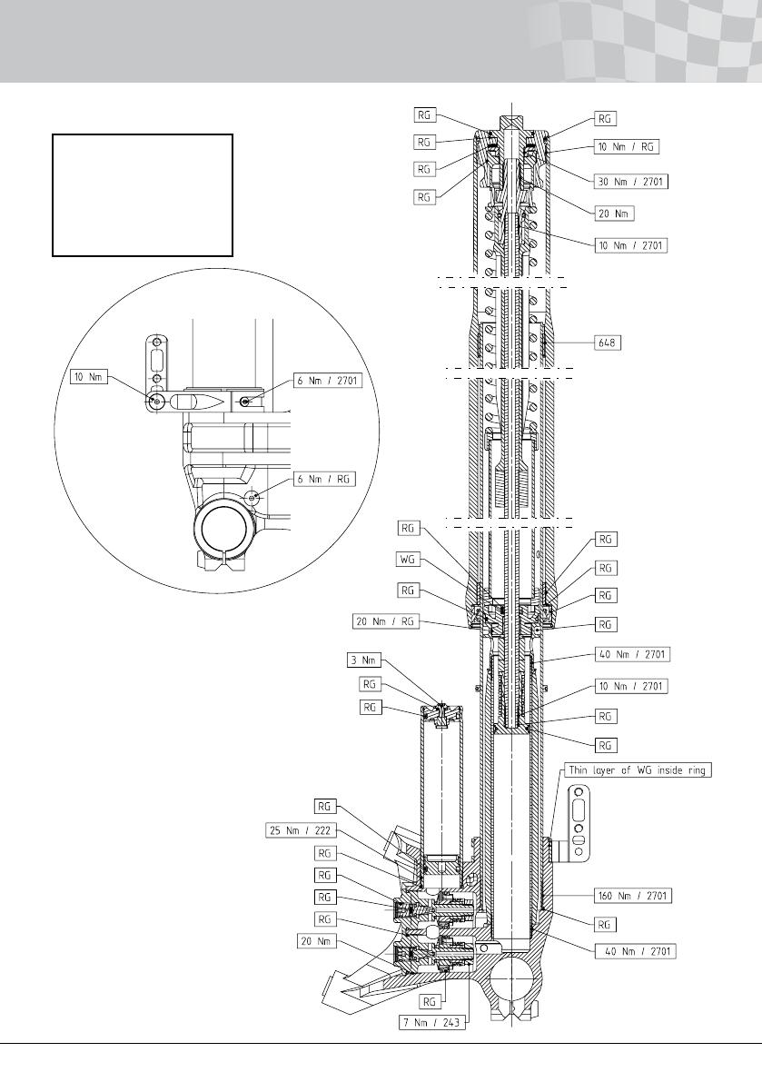
8
Technical Information
RG = Red Grease
WG = White Grease
222 = Loctite 222
648 = Loctite 648
2701 = Loctite 2701

9
Workshop Section
Tools 10
1 - Replace Spring 11
2 - Disassemble Front Fork 12
3 - Replace Seal 14
4 - Replace Inner/Outer Fork Leg 15
5 - Disassemble Shaft/ Adjust Length 17
6 - Assemble Front Fork 18
7 - Revalve 20

10
Required Tools
Pos Part No Description Notes
1 00727-02 Soft jaws
2 Wrench 14 mm
Wrench 17 mm
Wrench 19 mm
3 Torque Wrench 3/8’’
4 00794-01 Screwdriver Allen key 3 mm
5 Wire with hook
6 Heat gun
7 Teflon tape
8 Brass wire brush
9 00797-08 Sleeve pin
10 01797-04 Seal head tool
11 01765-03 Pull up tool
12 00720-02 Measure pin
13 00720-03 Pin tool
14 00786-05 Soft jaws clamp ø 43
15 00786-07 Soft jaws clamp ø 29
16 00715-01 Sharp screw driver
17 02810-01 Pull up holder tool
18 01781-01 Gas filling device
19 01309-01 Öhlins Front Fork fluid
20 00146-01 Öhlins red grease
21 00147-01 Öhlins white grease
22 01757-01 Attachment bar tool
23 01759-07 Bushing tool
Dismantling
01759-08 Bushing tool
Installation
24 01758-04 Bar guide
25 01797-07 Seal head tool
Loctite 648
Loctite 222
Rag
Waste fluid container
Tools
11
Spring
support
Spring
Preload
tube
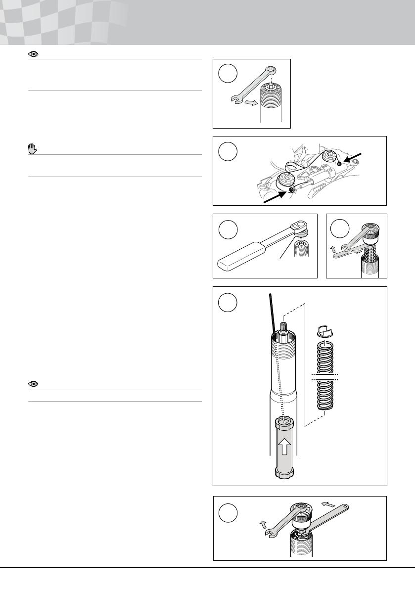
1 Replace Spring
1.1
Release the spring preload completely by turning
the adjustment nut counter clockwise as far as
possible. Use a 14 mm wrench or socket.
Caution!
Do not use the preload adjuster to tighten or
loosen the top cap assembly.
1.2
Loosen the screws that hold the fork legs in the
upper triple clamp.
1.3
Loosen the top cap assembly from the outer fork
leg. Use tool 00797-08.
1.4
Remove the top cap assembly from the shaft. Use
a 14 mm wrench on the top cap and a 19 mm on
the shaft.
1.5
Remove the spring support and the spring. Use a
wire with a hook and carefully pull up the preload
tube.
1.6
Check the oil level according to Chapter Oil level.
Note!
Use Öhlins Front Fork uid 01309-01 only.
1.7
Reinstall the preload tube, the new spring (with
the marking facing up) and the spring support.
1.8
Reinstall the top cap assembly to the shaft. Tight-
ening torque: 20 Nm.
1.9
Apply red grease to the top cap thread and o-ring.
Reinstall the top cap into the outer fork leg, with
the fork leg fully extended.
Use tool 00797-08. (See gure 1.3)
Tightening torque: 10 Nm.
Tighten the upper triple clamp and adjust the
preload according to Chapter Adjusters.
Tool 00797-08
1.1
1.2
1.3
1.4
1.5
Note!
This procedure can be performed with the front
fork still installed in the vehicle, but with the front
wheel off the ground.
1.8

12
Note!
This procedure can only be performed with the
front fork removed from the motorcycle.
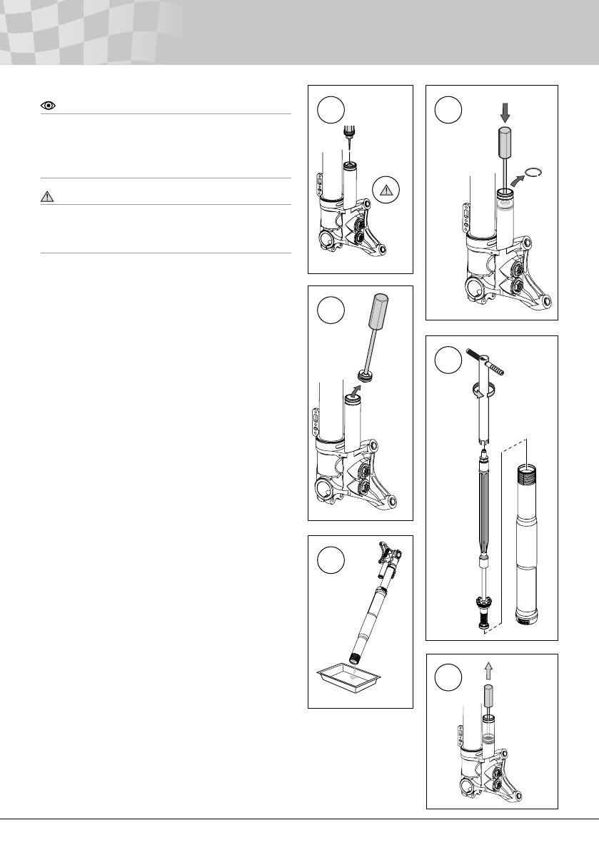
2.1
Fasten the fork leg in a vice with soft jaws.
2.2
Release the spring preload completely by turning
the adjustment nut counter clockwise as far as
possible. Use a 14 mm wrench or a socket.
2.3
Caution!
Do not use the preload adjuster to tighten or
loosen the top cap assembly.
Loosen the top cap assembly from the outer fork
leg. Use tool 00797-08.
2.4
Remove the top cap assembly from the shaft. Use
a 14 mm wrench on the top cap and a 19 mm
wrench on the shaft.
2.5
Remove the spring support and the spring. Use
a wire with a hook to carefully pull up the preload
tube.
2.6
Remove the screw and the o-ring from the reser-
voir end.
2.1
2.2
2.3
2.4
2.5
2.6
Top cap
assembly
Spring
support
Preload
tube
Reservoir
end
2 Disassemble Front Fork
Tool 00797-08
13
2 Disassemble Front Fork
Note!
Before releasing the gas pressure, count and
note the adjuster settings. Also check that the
gas pressure is correct. Then the adjusters
should be set in a fully open position.
Warning!
Releasing high pressure gas from the front fork
can be hazardous. Do not perform any kind of
service until gas pressure is completely released.
2.7
Release the nitrogen gas by inserting an injection
needle in the reservoir end through the rubber
valve.
2.8
Press down the reservoir end to remove the cir-
clip. Use tool 00720-03.
2.9
Remove the reservoir end. Use tool 00720-03.
2.10
Use tool 01797-04 and 01765-03 to remove the
shaft assembly from the fork leg.
2.11
Drain all oil from the fork leg.
2.12
Remove the gas piston, use tool 00720-02.
2.13
Disassemble the shaft assembly according to
Chapter Disassemble Shaft.
2.7 2.8
2.9
2.12
2.10
2.11
Injection
needle
Tool
00720-03
Tool
00720-03
Reservoir
end
Tool
00720-02
Gas piston
Tool
01765-03
Tool
01797-04
Shaft
assembly

14
Note!
This procedure can only be performed with the
front fork removed from the motorcycle.
Note!
Remove the top cap and shaft assembly
according to Chapter Disassemble Front Fork.
Then, continue below.
3.1
Remove the outer fork leg, clean the seal and
check its condition. If the seal is in good condition
apply Öhlins Front Fork Fluid to it before reassem-
bling the fork.
Note!
A damaged seal must be replaced!
3.2
Remove the circlip, the seal and nally the washer.
3.3
Apply a thin layer of Öhlins red grease to the
washer and the outside of the seal. Install the
washer and the seal into the outer fork leg. Install
the circlip into the groove.
Note!
It is important to use the correct grease in order
to achieve optimum fork function.
3.4
Apply some Öhlins Front Fork uid (01309-01)
on the inner fork leg’s outer surface. Slide on the
outer fork leg carefully on to the inner fork leg
(completely down).
Warning!
Be careful - Do not damage the fork seal!
3.5
Reassemble the fork legs according to Chapter
Assemble Front fork.
3 Replace Seal
3.1
3.2
3.3
3.4
Circlip
Seal
Washer
Circlip
Seal
Washer
Outer
fork leg
Inner fork leg

15
Note!
This procedure can only be performed with the
front fork removed from the motorcycle.
Note!
Remove the top cap and shaft assembly
according to Chapter Disassemble Front Fork.
Then, continue below.
4.1
Remove the outer fork leg.
4.2
Use a heat gun to warm up the fork bottom. Install
tool 00786-02 on the inner fork leg, just above the
lower ø5 mm oil bleed hole. Loosen and remove
the inner fork leg. Clean the thread thoroughly
from Loctite. We recommend to replace the o-ring!
4.3
Use a heat gun to carefully warm up the reser-
voir tube bottom. Use tool 00786-07 to loosen and
remove the reservoir tube. Clean the thread thor-
oughly from Loctite. We recommend to replace
the o-ring.
4.4
Install the new reservoir. Use tool 00786-07. Put
Loctite 222 on the thread.
Tightening torque 25 Nm.
4.5
Install the new inner fork leg using tool 00786-02.
Install the tool just above the lower ø 5 mm oil
bleed hole. Apply Öhlins red grease to the o-ring
on the cylinder tube extension.
Apply a thin layer of Öhlins Front Fork uid on the
inside of the inner fork leg, the lower half. Carefully
slide the inner fork leg over the o-ring and down to
the fork bottom thread.
Use Loctite 2701 on the threads.
Tightening torque 160 Nm.
4 Replace Inner/Outer Fork Leg
Outer
fork
leg
Inner
fork leg
Ø 5 mm
Tool
00786-02
4.1 4.2
4.3
4.5
Tool
00786-07
Loctite

16
4 Replace Inner/Outer Fork Leg
4.6
Apply some Öhlins fork uid (01309-01) on the in-
ner fork leg’s outer surface. Slide on the outer fork
leg carefully on to the inner fork leg (completely
down).
Warning!
Be careful - Do not damage the fork seal!
4.7
Reassemble the fork legs according to Chapter
Assemble Front Fork.
4.6
Inner
fork leg
Outer
fork leg

17
Note!
Remove the fork leg from the motorcycle.
Remove the top cap and shaft assembly
according to chapter Disassemble Front Fork.
Then, continue below.
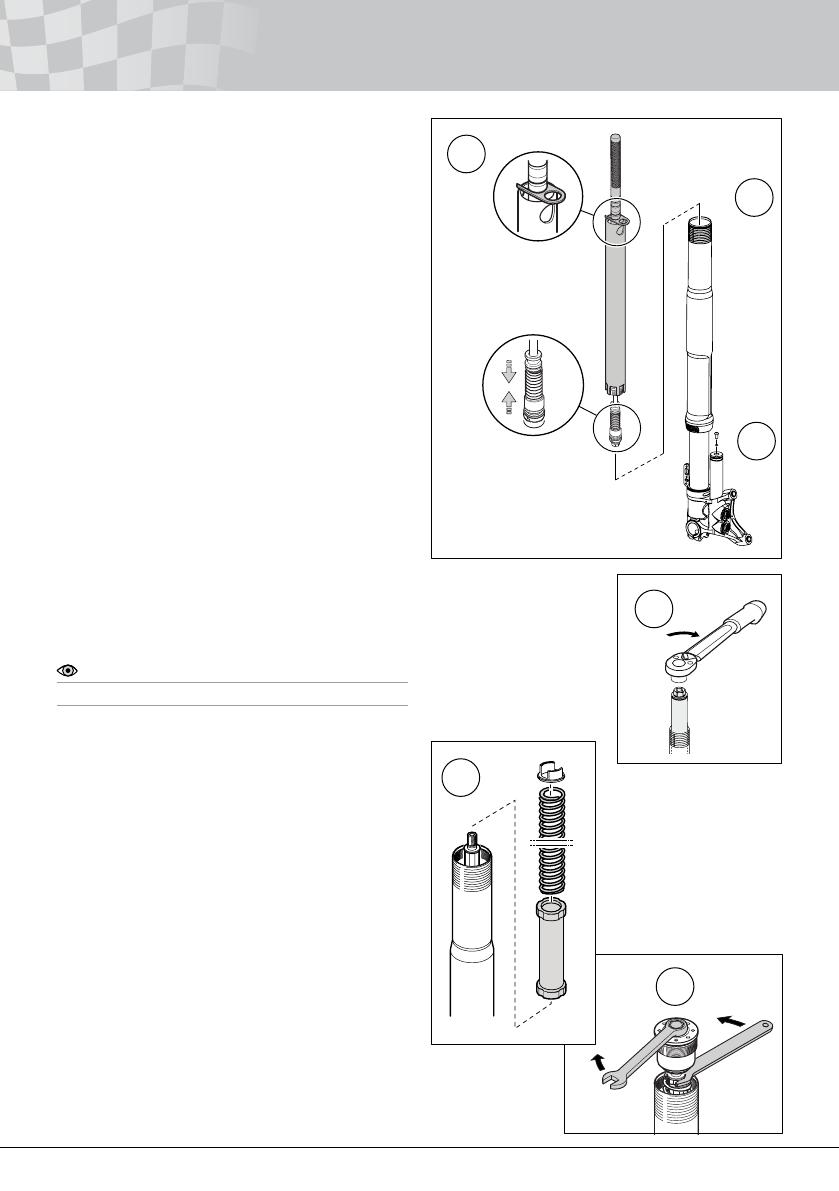
5.1
Put the shaft assembly in a vice using soft jaws
00727-02. Remove the piston, top-out spring and
sleeve in one unit. Use a 16 mm wrench.
Caution!
Do not tighten the jaws too hard, the shaft can be
damaged.
5.2
Remove the spacers and the o-ring.
5 Disassemble Shaft
5.1
5.2
5.2.1
5.3
5.5
5.6
Soft jaws
00727-02
Piston
Top-out spring
Sleeve
Spacer
01582-16
(8mm)
01582-15
(15mm)
O-ring
Support
ring
X-ring
Seal
head
O-ring
5.2.1 - Option; Adjust Length
• To adjust Length +8mm, retain stroke
130mm;
Move spacer 01582-15 (15mm) and place it
on the other side of the seal head, between
the bump rubber and the guide sleeve.
• To adjust Length +8mm and change stroke
to 138mm;
Remove spacer 01582-15 (15mm).
5.3
Remove the seal head from the shaft. Check the
support ring, x-ring and the o-ring. Replace them if
necessary. Use Öhlins white grease.
Caution!
Do not use sharp tools. Use plenty of Öhlins
white grease when installing an x-ring.
5.5
Wrap some teon tape around the shaft thread to
protect the x-ring from damages. Apply Öhlins red
grease to the tape and the shaft end. Reinstall the
seal head on the shaft.
5.6
Use a brass wire brush to clean the shaft from
tape. Reinstall the o-ring, spacer,
sleeve, topout spring and piston.
Use Loctite 2701 and a 16 mm wrench.
Tightening torque (piston): 10 Nm
and Adjust Length (Optional)

18
Note!
We recommend using the Öhlins Vacuum Filling
Machine for best performance. Contact Öhlins for
more information.
6.1
Open the compression and rebound adjusters
completely. Pour Öhlins Front Fork uid 01309-01
to the top edge of the reservoir. Carefully continue
to ll until the oil level reaches the upper reservoir
edge.
6.2
Carefully push the gas piston, with the teon band
and o-ring installed, to the reservoir bottom. Use
tool 00720-02.
Note!
Make sure that there is no air between the piston
and the oil.
6.3
Fill the inner fork leg with oil to approximately 20-
30 mm above the cylinder tube extension.
6.4
Carefully pump the gas piston up and down 10-20
times to bleed the system.
6.5
Check the o-ring on the reservoir end cap and
replace it if necessary. Install the reservoir end
cap into the reservoir tube using tool 00720-03.
Reinstall the circlip. Make sure that it stops in the
intended groove.
Note!
Nitrogen (N
2
) gas. Use pressure gauge (01781-01)
Warning!
Use of inammable gas for pressurising the front
fork can be hazardous. Use nitrogen gas (N
2
) only!
6.6
Dip the needle of the gas tool (01781-01) in red
grease and insert the needle through the gas ller
valve. Charge with gas to the correct pressure, ac-
cording to the spec. card.
Note!
Ensure that there is no leakage of gas or uid.
6 Assemble Front Fork
6.1 6.2
Cylinder
tube
Reservoir
Tool
00720-02
Gas
piston
6.3 6.4
6.5 6.6
Tool
01781-03
19
6.7
Install seal head tool 01797-04 and pull-up tool
01765-03 on the shaft assembly. Pull the pull-up
tool and push the seal head tool at the same time
to contract the top-out spring. Install tool 02810-01
on tool 01765-03 to keep the contraction. Apply
Öhlins red grease to the seal head thread and the
o-ring.
6.8
Assemble the complete shaft assembly into the
cylinder tube all the way down. Tighten it by hand.
Check the gas pressure again according to the
spec. card.
6.9
Tighten the gas lling screw and o-ring to 3Nm.
6.10
Remove tool 02810-01 and 01765-03.
Use tool 01797-07.
Tightening torque: 20Nm
6.11
Check oil level according to chapter Oil level.
Note!
Use Öhlins Front fork uid 01309-01 only.
6.12
Reinstall the preload tube, spring (with marking
facing up) and spring support.
6.13
Reinstall the top cap assembly to the shaft. Tight-
ening torque: 20 Nm.
6.14
Apply Öhlins grease on the top cap thread and o-
ring, and reinstall the top cap into the outer fork
leg, with the fork leg fully extended.
Use tool 00797-08.
Tightening torque: 10 Nm.
6.15
Adjust the preload, compression and rebound.
6 Assemble Front Fork
6.7
6.9
6.8
Tool
01765-03
Tool
02810-01
Tool
01797-04
Top-out
spring
6.10
Tool
01797-07
6.12
6.13
/