Silex technology Server SX-500-1402 User manual
- Category
- Networking
- Type
- User manual
This manual is also suitable for

SX-500-1402
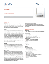
Serial Device Server
Cryptographic Officer Guidance Manual
Part Number 140-00188-210A

© 2009 Silex Technology America, Inc. All rights reserved.
June2009
Silex Technology America SPECIFICALLY DISCLAIMS THE IMPLIED WARRANTIES OF MERCHANTABILITY AND
FITNESS OF THIS PRODUCT FOR A PARTICULAR PURPOSE. Silex shall not be liable for any errors contained in this
manual or for any damages resulting from loss of use, data, profits, or any incidental or consequential damages arising from
the use of SILEX products or services. The information contained in this documentation is subject to change without notice.
Information and descriptions contained herein are the property of Silex. Such information and descriptions may
not be copied, disseminated, or distributed without the express written consent of Silex. This publication is
subject to change without notice.
The firmware embedded in this SX-500 serial device server includes the eCos operating system. eCos and
certain other software programs used in the SX-500 are licensed under GNU GPL compatible Free Software
Licenses (with the eCos exception clause). In compliance with these licenses, you can obtain the relevant
source code at no charge by contacting Silex at [email protected].
Trademarks
All company or product names referenced in this document may be trademarks or registered trademarks of
their respective owners.
Silex Technology America, Inc.
www.silexamerica.com
Part Number 140-00188-210A


Contents
About This Reference Guide....................................................................................................................................1
Safety Precautions................................................................................................................................................1
Emissions Disclaimer............................................................................................................................................1
Chapter 1: Introduction............................................................................................................................................3
PHYSICAL PORTS...............................................................................................................................................4
Logical Ports.........................................................................................................................................................4
Configuration ........................................................................................................................................................5
Physical Protection................................................................................................................................................7
Secure Operation..................................................................................................................................................7
Chapter 2
Installing the Serial Device Server Hardware...........................................................................................................8
Verify Package Contents ......................................................................................................................................8
Installing the Serial Device Server........................................................................................................................8
Monitoring Serial Device Server Status .............................................................................................................10
Chapter 3
Configuring the Serial Device Server......................................................................................................................11
Basic Configuration Requirements......................................................................................................................11
Configuration Methods........................................................................................................................................12
First-Time IP Address Configuration ..................................................................................................................13
Using a Web Browser to Configure the Serial Device Server.............................................................................15
Using the Internal Command Console to Configure the Serial Device Server....................................................19
Chapter 4
Using the Serial Device Server with Your Application.............................................................................................21
Serial Port Emulator............................................................................................................................................21
Raw TCP connection..........................................................................................................................................22
RFC 2217 Remote Modem Control Support.......................................................................................................23
ECable Mode......................................................................................................................................................23
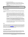
Print Server Mode...............................................................................................................................................24
FTP.....................................................................................................................................................................24
Console Mode Switching.....................................................................................................................................25
AT Commands....................................................................................................................................................25
Chapter 5
Advanced Configuration.........................................................................................................................................27
Factory Default Settings......................................................................................................................................27
Restoring Factory Default Settings..................................................................................................................28
Modifying TCP/IP Settings ................................................................................................................................28
Using AT Modem Commands.............................................................................................................................29
Standard AT Commands Supported................................................................................................................30
Response Codes.................................................................................................................................................32
Chapter 6
Troubleshooting......................................................................................................................................................33
Contents Silex Page i
Part Number 140-00188-210A

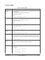
Chapter 7
Product Specifications............................................................................................................................................35
TCP Port Connections........................................................................................................................................36
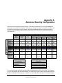
Appendix A
Advanced Security Configuration............................................................................................................................37
Appendix B
Console Commands...............................................................................................................................................41
Wireless and Network Security Commands........................................................................................................41
Port Commands..................................................................................................................................................47
Server Information Commands...........................................................................................................................48
Service Commands.............................................................................................................................................50
String Commands...............................................................................................................................................52
TCP/IP Commands.............................................................................................................................................53
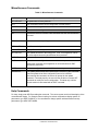
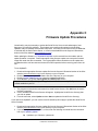
Firmware Update.................................................................................................................................................58
Miscellaneous Commands..................................................................................................................................59
Help Commands.................................................................................................................................................59
Appendix C
Firmware Update Procedures.................................................................................................................................61
Appendix D
Safety and Regulatory Notices...............................................................................................................................63
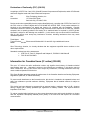
Information for United States Users....................................................................................................................63
Declaration of Conformity (FCC) (SX-500)..........................................................................................................64
Information for Canadian Users (IC notice) (SX-500)..........................................................................................64
Information for European Users (SX-500)...........................................................................................................65
Declaration of Conformity (CE) (SX-500)............................................................................................................65
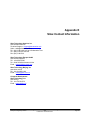
Appendix E
Silex Contact Information........................................................................................................................................66
Figures
Figure 1 SX-500 ......................................................................................................................................................3
Figure 2 TCP/IP Window.......................................................................................................................................28
Tables
Table 1 Package Contents......................................................................................................................................8
Table 2 Status Monitors .........................................................................................................................................10
Table 3 Factory Default Settings............................................................................................................................27
Table 4 TCP/IP Settings........................................................................................................................................29
Table 5 AT Commands..........................................................................................................................................30
Contents Silex Page ii
Part Number 140-00188-210A

Table 6 Extended AT Commands..........................................................................................................................31
Table 7 Response Codes......................................................................................................................................32
Table 8 Product Specifications..............................................................................................................................35
Table 9 Radio Performance Specifications............................................................................................................35
Table 10 TCP Port Connections............................................................................................................................36
Table 11 Network Commands...............................................................................................................................41
Table 12 Port Commands......................................................................................................................................47
Table 13 Server Information Commands...............................................................................................................48
Table 14 Service Commands.................................................................................................................................50
Table 15 String Commands...................................................................................................................................52
Table 16 TCP/IP Commands.................................................................................................................................53
Table 17 Firmware Update....................................................................................................................................58
Table 18 Miscellaneous Commands......................................................................................................................59
Contents Silex Page iii
Part Number 140-00188-210A

About This Reference Guide
Safety Precautions
To prevent damage to the Serial Device Server’s electronic circuit components, follow established
ESD practices and procedures for handling static-sensitive devices. All ESD-sensitive components must be
stored and shipped in ESD-conductive bags or bubble-wrap and labeled as such using the standardized
ESD adhesive warning label.
Ethernet electrical wiring must be at least 6 feet from bare power wiring or lightning rods and
associated wires, and at least 6 inches from other types of wire (antenna wires, doorbell wires, wires from
transformers to neon signs), steam or hot water pipes, and heating devices.
Protectors and grounding wire placed by the service provider must not be connected to, removed,
or modified by the customer.
Emissions Disclaimer
Regulatory compliance information can be found in Appendix D of this manual. Final emission certification per
FCC, CE and other agency requirements are the responsibility of the OEM using any printed circuit assemblies or
other items used in this developer’s kit in their saleable packaged product.
About This Reference Guide Silex Page 1
Part Number 140-00188-210A

REVISION HISTORY
About This Reference Guide Silex Page 2
Part Number 140-00188-210A
Rev.
No.
Date Revision by Comments
A 2009.08.13 Lee Aydelotte Initial Release

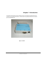
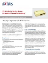
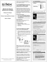
Chapter 1: Introduction
The SX-500-1402 Serial Device Server provides a FIPS 140 compliant encrypted wireless LAN
connection for an attached client device. The client device may attach to the SX-500 via a serial
port or wired Ethernet port.
Figure 1 SX-500
Introduction Silex Page 3
Part Number 140-00188-210A

PHYSICAL PORTS
The physical ports on the SX-500 are as follows:
Port Name Description
Power Jack for attachment of external power supply
Ethernet RJ-45 connector for attachment of Ethernet cable
Serial DB-9 connector for attachment of serial interface cable
Wireless RP-SMA connector for attachment of an external antenna
Button Momentary push button
LED Green, Yellow and Orange LEDs
For installation and connection of the interface ports, refer to Chapter 2.
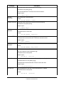
Logical Ports
The SX-500 has logical interfaces for transfer of data and for configuration and control of the unit.
These logical interfaces may share a physical port. The application firmware in the SX-500
separates and routes the data to the appropriate internal firmware task associated with the logical
interface. For network ports (Ethernet, Wireless) this separation is based on the TCP or UDP
protocol port number. For the serial port, data or control/status mode is controlled by specific
protocol strings, only one mode is active at a time. Serial port control/status mode is only
available if the unit is explicitly configured to allow it. The following table describes the logical
interfaces of the unit when operating in a FIPS 140-2 approved mode.
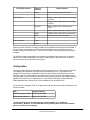
FIPS-140-2 Interface Physical
Interface
Logical Interface
Data Input Serial Plaintext data for transmission to network
Ethernet Plaintext data for bridging to wireless
network
Wireless Ciphertext data for Serial or Ethernet port
Data Output Serial Plaintext data received from wireless
network
Ethernet Plaintext data received from wireless
network
Wireless Ciphertext data from Serial or Ethernet port
Control Input Ethernet Control data for console task received via
Telnet
Control data for web config task received
via HTTP
Wireless Control data for console task received via
Telnet
Control data for web config task received
via HTTP
Introduction Silex Page 4
Part Number 140-00188-210A

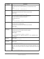
FIPS-140-2 Interface Physical
Interface
Logical Interface
Button Invoke configuration/status function
Status Output Ethernet Plaintext status response from console task
via Telnet
Plaintext status response from web config
via HTTP
Wireless Status response from console task via
Telnet
Status response from web config via HTTP
Serial Plaintext status response from button push
LEDs Indicate link and unit error status
Power Interface Power
Serial
When the module enters an error state, all Data Input and Data Output interfaces are disabled. If
an error state is encountered, the LED interface will indicate the error by blinking for several
seconds, and then the unit will reset. The unit will not send or receive any data until the reset is
complete.
The SX-500 performs cryptographic self tests during initialization after power up or a firmware
induced reset. Until the self tests are complete, no data input or output interfaces are active. If
the self test fails, the unit will enter an error state.
Configuration
The Cryptographic Officer is responsible for configuring the unit for use in the target environment.
See Chapter 3 and Appendix A for instructions on configuring the unit. The peripheral unit
(usually a PC) being used to configure the SX-500 must be directly connected to the unit via a
crossover cable or local hub which is not connected to any LAN, WLAN or other larger network.
This will enable manual transport and electronic entry of secret and private keys (RSA private key
and WPA Pre-Shared Key) in a plaintext form. Even if RSA private keys are protected with a
PEM passphrase when entered, they are still considered to be in plaintext form.
For the SX-500 to operate in FIPS 140-2 approved mode, the wireless security configuration must
be set as follows:
Item Required Setting
Wireless Encryption Mode WPA2 (AES-CCMP)
Wireless Authentication PSK or TLS or PEAP
The SX-500 allows other security settings for interoperability in non FIPS 140
environments. However, use of the SX-500 with any settings other than those indicated
above is not FIPS 140-2 compliant.
Introduction Silex Page 5
Part Number 140-00188-210A

In particular, the WPA2-WPA transition mode is NOT FIPS 140-2 compliant. Only networks
exclusively using WPA2 (AES-CCMP) encryption comply.
The current security settings for the device may be observed by logging into the unit web server
and navigating to the network security page, which will show the currently active and configured
values for the above parameters (and others). The settings may also be observed with the
configuration console command SHOW NW. This should be done after configuration and before
use to verify that the device is properly configured for the intended target environment.
The SX-500 is validated at level 1, which means it has no physical security beyond the physical
protection of its metal case, and is presumed to be used in a secure environment. If the unit is to
be left unused in an unsecured area, or is to be transported to a new location via unsupervised
means, it is recommended that the Cryptographic Officer zeroize the device. This is done with
the configuration console command ZEROKEYS. After zeroization the unit will need to be re-
configured before wireless communication in FIPS compliant mode are possible.
The Cryptographic Officer must be aware that all configuration program inputs are in
plaintext for purposes of FIPS 140-2 compliance regardless of the transport encoding
used. The only FIPS 140-2 cryptographic protection claimed for this module is for the
wireless link between the unit and an associated Access Point.
If WPA2-PSK mode is being used, the PSK must be entered by the Cryptographic officer
on an isolated network with the machine containing Cryptographic Officer’s web browser
directly connected to the SX-500 and not connected via a LAN. The same is true for entry
of externally generated RSA private keys/public certificates.
The Crypographic officer must zeroize the module when transitioning the device configur-
ation from a FIPS-140-2 approved mode to a non-approved mode. The Cryptographic Of-
ficer should zeroize the module before resetting the configuration to factory defaults. If
this is impossible, because the reason for resetting is the connection to the unit is im-
possible, the unit must be zeroized after the configuration reset is complete and connec-
tion has been restored.
There are two types of bypass states possible with the module (non-approved modes).
The first is to use any wireless encryption/authentication combination not specified above
as being FIPS 140-2 compliant and then reset the unit. The second is to configure the unit
to not be in Ethernet to Wireless mode, plug in a wired Ethernet cable, and then reset the
unit.
If WPA2-PSK mode is being used, the PSK must be entered by the Cryptographic officer on an
isolated network with the machine containing Cryptographic Officer’s web browser directly
connected to the SX-500 and not connected via a LAN. The same is true for entry of externally
generated RSA private keys/public certificates.
In addition to the wireless security settings above, the following settings must be made for
operation in FIPS 140-2 mode:
Item Required Setting
HTTPS Disabled (factory default)
S-Telnet Disabled (factory default)
TCP data service SSL Disabled (factory default)
Serial port console mode string NULL (disabled – factory default)
Serial port filter TRAP (factory default)
Introduction Silex Page 6
Part Number 140-00188-210A

Physical Protection
There are no user serviceable parts inside the SX-500 enclosure. If the enclosure should be
opened for any reason, the Cryptographic Officer should zeorize the module before the enclosure
is opened.
Secure Operation
The Cryptographic Officer and any users of the SX-500 module must be familiar with the SX-500
Cryptographic Security Policy and must follow its guidelines for proper operation.
Introduction Silex Page 7
Part Number 140-00188-210A

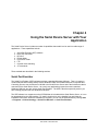
Chapter 2
Installing the Serial Device Server Hardware
The Serial Device Server includes most of the hardware and software components required for
installation. The one item that you will need to purchase separately is a cable to connect your serial
device to the Serial Device Server (this cable is not included because of the wide variety of connector
types used on serial devices).
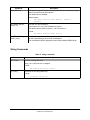
Verify Package Contents
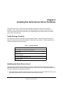
The Serial Device Server includes the components listed in Table 1. Please ensure that all materials
listed are present and free from visible damage or defects before proceeding. If anything appears to be
missing or damaged, please contact Silex.
Table 1 Package Contents
Description
SX-500 Base Unit w/external pole antenna
Setup Guide
CD-ROM containing Serial Port Emulator Software, and User’s
Reference Guide
AC Power Supply with power cord
Warranty Card
Installing the Serial Device Server
Follow the steps below to install the Serial Device Server. The Serial Device Server’s factory default
settings should be sufficient for most serial connections; however, some of the configuration settings may
have to be changed for your particular installation.
1. Before attempting to install the Serial Device Server, make sure you have installed and set up your
serial device as described in the documentation that came with the device.
Installing the Serial Device Server Silex Page 8
Part Number 140-00188-210A

2. Write down the 12-digit MAC (Media Access Code) address printed on the label located on the
bottom of the Serial Device Server (for example: 004017023F96). You may need this number in
order to configure the Serial Device Server.
3. If you have a wireless model, connect the antenna to the unit.
4. Connect the Serial Device Server to your serial device. If you are using RS-232, you may use
standard PC cabling (you should normally use a null modem crossover cable). The 9-pin connector
pinouts and cabling are as follows:
RS-232 connector pinouts and cabling
5. Plug the Serial Device Server power supply adapter into a suitable AC receptacle, and then plug the
power supply cable into the Serial Device Server. Alternatively, you can use pin 9 on the 9-pin
connector to provide power to the Serial Device Server (1 amp @ +5V is required).
When power is applied all three LEDs will be lit. The Serial Device Server will run through a
sequence of power-up diagnostics for a few seconds.
• If the Serial Device Server is operating properly, the green and yellow LEDs will turn off and then
will show the device status as shown in Table 2 in the next section. The orange LED should remain solidly
illuminated.
• The unit powers up in the Normal mode, which provides for connection from the network to
device(s) connected to the serial port of the Serial Device Server.
• If the orange LED blinks continuously in a regular pattern, a problem exists. If this is the case, try
powering the unit OFF and then ON again.
.
6. Connect the Serial Device Server to your network through a switch or hub using
a category 5 (CAT5) Ethernet cable. Then cycle power on the device to switch the server into wired
mode and switch off the wireless networking functionality as long as the cable is plugged in.
Installing the Serial Device Server Silex Page 9
Part Number 140-00188-210A
NOTE: Pin 9 is normally configured for supplying +5V from an external power source in lieu of using the AC power
supply adapter.
NOTE: SILEX RECOMMENDS USING A HARDWIRED ETHERNET CONNECTION FOR CONFIGURING
WIRELESS SERIAL DEVICE SERVERS. If you have a wireless Serial Device Server model and cannot use an
Ethernet connection, refer to step 4 in the First Time IP Address Configuration section of this chapter for
instructions on how to set up the Serial Device Server using a completely wireless Ad Hoc environment.
Device Keys (unit private key and WPA2-PSK) must be entered via an isolated wired connection

7. The Serial Device Server’s IP address must be configured before a network
connection is available. If your network offers DHCP (Dynamic Host Configuration Protocol), the
Serial Device Server will automatically search for a DCHP server upon power up and obtain an IP
address. If your network does not offer DHCP, a static (fixed) IP address must be assigned (see your
system administrator for assistance). If you use DHCP, make sure that the length of the DHCP lease
is adequate so that the IP address of the Serial Device Server does not change.
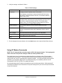
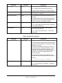
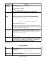
Monitoring Serial Device Server Status
You can monitor the Serial Device Server status using the yellow, green and orange LED status
indicators on the monitor. Table 2 defines the functions of the LED status indicators.
Table 2 Status Monitors
Function State Status
Power
Orange
On The Serial Device Server is receiving power
Off The Serial Device Server is not receiving power
Slow Blink ( 0.6Hz) Firmware update in progress
Fast Blink (5-10Hz)
The Serial Device Server is malfunctioning or
cryptographic error detected.
Network Status
Yellow or Green
Yellow Off
Green Off
No network connection
Yellow On
Green Off
Wireless network connected, not authenticated.
Yellow On
Green On
Wireless network active (authenticated) in FIPS 140-2
approved mode.
Yellow Blinking (5Hz)
Green On
Wireless network data received in FIPS 140-2 approved
mode.
Yellow off
Green Blinking (½ Hz)
Bypass (non-approved) mode, no wireless network
connection
Yellow on
Green Blinking (½ Hz)
Bypass mode, wireless network connected.
Yellow Blinking (5 Hz)
Green Blinking (5 Hz)
Bypass mode, wireless network data received
Installing the Serial Device Server Silex Page 10
Part Number 140-00188-210A

Chapter 3
Configuring the Serial Device Server
This chapter describes the methods for configuring the basic settings of the Serial Device Server,
including the IP address, serial port settings, and wireless security. The Serial Device Server also has an
extensive range of advanced configuration capabilities that are described in Chapter 5, Appendix A, and
Appendix B. The Serial Device Server configuration should be done by a network administrator or
another person with technical knowledge of TCP/IP networking and serial communications.
Basic Configuration Requirements
In order to use the Serial Device Server, the following basic parameters must be configured:
TCP/IP Settings:
• IP Address
• Subnet Mask
• Router Address
Note: The TCP/IP settings can be automatically configured using DHCP.
Wireless Configuration Settings:
• SSID
• Mode (Infrastructure or Ad Hoc)
• Channel (required only if using Ad Hoc mode)
Security Settings:
• Wireless Encryption Mode (WPA2, WPA, WPA2-WPA, WEP)
• Wireless Encryption Settings
• Wireless Authentication Mode (WPA-PSK, Open System, Shared Key, TTLS, TLS, LEAP, PEAP)
• Wired Authentication Mode (TTLS, TLS, PEAP)
• Authentication Settings
Note: There are numerous possible encryption and authentication settings, and every network can
have different settings. Please refer to Appendix A for a detailed summary of these settings.
Serial Port Settings (must match the settings of the attached serial device):
• Baud Rate (Speed)
• Parity
• Character Size
Configuring the Serial Device Server Silex Page 11
Part Number 140-00188-210A

• Flow Control
In addition to the above parameters, the Serial Device Server allows you to configure numerous other
capabilities. These other capabilities provide you with the unparalleled flexibility to use the Serial Device
Server on virtually any 802.11 or Ethernet network with a wide range of serial devices.
Configuration Methods
There are two ways to configure the Serial Device Server:
• Internal Web Pages (HTTP). You can use any standard web browser to access the Serial Device
Server internal web pages. These web pages provide an easy-to-use graphical interface for
configuring the Serial Device Server. In order to use the internal web pages for the first time, you
must assign the Serial Device Server IP address using some other method (for example, DHCP
or arp/ping). This initial IP address assignment need only be done one time.
• Internal Command Console. The internal command console provides a sophisticated command
line interface for advanced users to configure the Serial Device Server. It can be accessed by
connecting a serial cable to the serial port and using console mode switching as descried in
chapter 4. Once the IP address has been assigned, the internal command console can also be
accessed via TELNET, or via the internal web pages. NOTE: when operating in a FIPS 140-2
approved mode, the console is not available via the serial port.
If you have a Serial Device Server wireless model, Silex recommends that you temporarily plug
the Serial Device into a wired Ethernet network during the configuration process. Although it is
possible to configure the Serial Device Server with a completely wireless setup, it is much simpler to
perform the process using a wired Ethernet connection. This is primarily because the wireless security on
most wireless networks prevents the addition of a new wireless device unless all security parameters are
first entered into that device. As a result, you must set up a temporary dedicated ad hoc wireless network
in order to configure the Serial Device Server in a completely wireless environment (refer to the step 4 in
the First Time IP Address Configuration section of this chapter for instructions on how to set up the Serial
Device Server using a completely wireless Ad Hoc environment). This is required when entering
security encryption keys (RSA private key or WPA2-PSK).
Configuring the Serial Device Server using each of the above methods is described in the following
sections of this chapter.
Page 12 Silex Configuring the Serial Device Server
Part Number 140-00188-210A

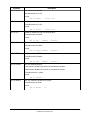
First-Time IP Address Configuration
If you are configuring the Serial Device Server from a non-Windows computer or if you cannot use an
Ethernet connection, you must first configure the Serial Device Server IP address. Note that it is only
necessary to perform this task one time -- once the address has been configured, the Serial Device
Server can be accessed from any computer on the network that has the appropriate privileges. The steps
are as follows:
1. If your network has a DHCP server and you can use an Ethernet connection to the Serial Device
Server:
a. Make sure your PC is connected and has access to your network.
b. Connect an Ethernet cable from your network hub to the Serial Device Server (if you
have a wireless Serial Device Server and do not have hardwired capabilities, then you
must go to Step 4 below for setup instructions).
c. Power on the Serial Device Server.
d. The administration program on most DHCP servers logs the IP address and MAC
address of each DHCP client. The MAC address of the Serial Device Server can be
found on the label affixed to the unit. If your DHCP server has logged this information,
write down the IP address of the Serial Device Server for future reference. You are now
ready to configure the Serial Device Server (skip the remainder of this section).
e. If your DHCP server does not provide client information or if you do not have access to
the DHCP server, then you can get the IP address by connecting a serial device such as
a printer, a Windows PC running HyperTerminal, or another serial device capable of
printing ASCII characters to the serial port the Serial Device Server). Your serial device
must be set at 115.2Kbps, 8-bit character size, and no parity.
f. With the serial device and Serial Device Server switched on and ready, press the Reset
pushbutton on the Serial Device Server. This will cause the Serial Device Server
configuration data to be sent to the connected serial device. The serial device should
display or print the current IP address assigned to the Serial Device Server by your
network DHCP service. Write down this address for future reference. You are now ready
to configure the Serial Device Server (skip the remainder of this section).
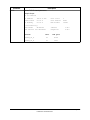
2. If you can connect the Serial Device Server via Ethernet but do not have a DHCP server, then
you must use the following procedure for the first-time IP configuration of the Serial Device Server.
a. Make sure your PC is connected and has access to your network
b. Connect an Ethernet cable from your network hub to the Serial Device Server. The
Serial Device Server must be on the same network segment as the PC (that is, there can
be no router between the Serial Device Server and the PC).
c. From the Windows Command Prompt (MS-DOS Prompt), the Mac OS X Terminal Utility,
or the UNIX/Linux command line, enter the command
arp –s ipaddress macaddress
Configuring the Serial Device Server Silex Page 13
Part Number 140-00188-210A
NOTE: Skip this section if you have already configured the SX-500 IP address

ping ipaddress
Where ipaddress is the desired IP address of the Serial Device Server and
macaddress is the MAC address of the Serial Device Server (found on the label
affixed to the Serial Device Server). For example:
arp –s 192.168.5.53 00:40:17:00:00:01
ping 192.168.5.53
Note that Windows systems use the format xx-xx-xx-xx-xx-xx for the MAC
address (for example, 00-0017-00-00-01).
You will see a reply from the Serial Device Server with the number of bytes and
other information if the address was successfully set.
If you get an error message or no response, then the IP address was not set. If
this is the case, the Serial Device Server may not be at its default configuration.
To reset the Serial Device Server to its default settings, hold down the reset
pushbutton for more than five seconds.
d. You are now ready to configure the Serial Device Server (skip the remainder of this
section).
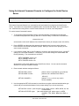
3. If you are using a wireless connection for the first-time configuration of the Serial Device Server,
you must set up a temporary ad hoc wireless connection as described in the following steps. Please
note that because this is a fairly complex process, we do not recommend it unless it is not possible to
use a wired connection.
a. Disconnect your PC and the Serial Device Server from your network, and temporarily set
the PC settings as follows:
• IP address: 192.0.0.191
• Wireless Mode: Ad Hoc (sometimes referred to as Peer-to-Peer)
• Channel: 11
• SSID (or wireless network name): serserv
b. Power on the PC and the Serial Device Server. You can connect to the Serial Device
Server by specifying its default IP address of 192.0.0.192 using a web browser as
described in the next section. When you have connected to the Serial Device Server, you
must then change the IP address and enter the required wireless networking parameters
using either the web browser interface or the internal command console (see next two
sections) for operation on your wireless network.
c. After you complete the entire Serial Device Server configuration process, you must set
your PC back to its original network settings.
Page 14 Silex Configuring the Serial Device Server
Part Number 140-00188-210A
NOTE: Skip the following step if you have configured IP address of the Serial Device Server using an Ethernet cable.
Page is loading ...
Page is loading ...
Page is loading ...
Page is loading ...
Page is loading ...
Page is loading ...
Page is loading ...
Page is loading ...
Page is loading ...
Page is loading ...
Page is loading ...
Page is loading ...
Page is loading ...
Page is loading ...
Page is loading ...
Page is loading ...
Page is loading ...
Page is loading ...
Page is loading ...
Page is loading ...
Page is loading ...
Page is loading ...
Page is loading ...
Page is loading ...
Page is loading ...
Page is loading ...
Page is loading ...
Page is loading ...
Page is loading ...
Page is loading ...
Page is loading ...
Page is loading ...
Page is loading ...
Page is loading ...
Page is loading ...
Page is loading ...
Page is loading ...
Page is loading ...
Page is loading ...
Page is loading ...
Page is loading ...
Page is loading ...
Page is loading ...
Page is loading ...
Page is loading ...
Page is loading ...
Page is loading ...
Page is loading ...
Page is loading ...
Page is loading ...
Page is loading ...
Page is loading ...
-
 1
1
-
 2
2
-
 3
3
-
 4
4
-
 5
5
-
 6
6
-
 7
7
-
 8
8
-
 9
9
-
 10
10
-
 11
11
-
 12
12
-
 13
13
-
 14
14
-
 15
15
-
 16
16
-
 17
17
-
 18
18
-
 19
19
-
 20
20
-
 21
21
-
 22
22
-
 23
23
-
 24
24
-
 25
25
-
 26
26
-
 27
27
-
 28
28
-
 29
29
-
 30
30
-
 31
31
-
 32
32
-
 33
33
-
 34
34
-
 35
35
-
 36
36
-
 37
37
-
 38
38
-
 39
39
-
 40
40
-
 41
41
-
 42
42
-
 43
43
-
 44
44
-
 45
45
-
 46
46
-
 47
47
-
 48
48
-
 49
49
-
 50
50
-
 51
51
-
 52
52
-
 53
53
-
 54
54
-
 55
55
-
 56
56
-
 57
57
-
 58
58
-
 59
59
-
 60
60
-
 61
61
-
 62
62
-
 63
63
-
 64
64
-
 65
65
-
 66
66
-
 67
67
-
 68
68
-
 69
69
-
 70
70
-
 71
71
-
 72
72


Silex technology Server SX-500-1402 User manual
- Category
- Networking
- Type
- User manual
- This manual is also suitable for
Ask a question and I''ll find the answer in the document
Finding information in a document is now easier with AI
Related papers
-
 Silex technology SX-500 User manual
-
 Silex technology SX-600 User manual
-
 Silex technology SX-2000U2 User manual
-
 Silex technology Silex SX-5000U2 User manual
-
 Silex technology SX-SDWAG User manual
-
 Silex technology SX-500 Series User guide
-
 Silex technology SX-510 User manual
-
 Silex technology Silex SX-1000U User manual
-
 Silex technology 40190-100 User manual
-
Silex technology E1171 Datasheet


Other documents
-
Silex SX-590-1402 User manual
-
KYOCERA TASKalfa 550c User manual
-
Silex SD-320AN Installation guide
-
-
-
Silex BR-300AN Installation guide
-
 Datamax-ONeil DMXrfNet III Network WiFi Installation guide
-
-
-
