Page is loading ...

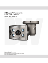
MEGApix® Panoramic
2.1MP 180° Camera
DWC-PV2M4T
User’s Manual Ver. 1.0 / 2015.04.21
Before installing and using the camera, please read this manual carefully.
Be sure to keep it handy for future reference.

S
af
et
y
I
nf
or
ma
tion
1
Warning
Precaution
This symbol indicates that dangerous voltage
consisting a risk of electric shock is present within
this unit.
This exclamation point symbol is intended to alert the
user to the presence of important operating and
maintenance (servicing) instructions in the literature
accompanying the appliance.
WARNING
To prevent damage which may result in fire or electric shock
hazard, do not expose this appliance to rain or moisture.
WARNING
1.
Be sure to use only the standard adapter that is specified in
the specification sheet. Using any other adapter could cause
fire, electrical shock, or damage to the product.
2. Incorrectly connecting the power supply or replacing battery
may cause explosion, fire, electric shock, or damage to the
product.
3.
Do not connect multiple cameras to a single adapter.
Exceeding the capacity may cause excessive heat generation
or fire.
4. Securely plug the power cord into the power receptacle.
Insecure connection may cause fire.
5. When installing the camera, fasten it securely and firmly.
A falling camera may cause personal injury.
6. Do not place conductive objects (e.g. screw drivers, coins,
metal items, etc.) or containers filled with water on top of
the camera. Doing so may cause personal injury due to fire,
electric shock, or falling objects.
7. Do not install the unit in humid, dusty, or sooty locations.
Doing so may cause fire or electric shock.
8.
If any unusual smells or smoke come from the unit, stop
using the product. Immediately disconnect the power
source
and contact the service center. Continued use in
such a
condition may cause fire or electric shock.
9. If this product fails to operate normally, contact the nearest
service center. Never disassemble or modify this product in
any way.
10. When cleaning, do not spray water directly onto parts of the
product. Doing so may cause fire or electric shock.
Precaution
Operating
•
Before using, make sure power supply and all other parts are
properly connected.
•
While operating, if any abnormal condition or malfunction
is observed, stop using the camera immediately and contact
your dealer.
Handling
•
Do not disassemble or tamper with parts inside the camera.
•
Do not drop the camera or subject it to shock or vibration as
this can damage the camera.
•
Clean the clear dome cover with extra care. Scratches and
dust can ruin the quality of the camera image.
Installation and Storage
•
Do not install the camera in areas of extreme temperature,
exceeding the allowed range.
•
Avoid installing in humid or dusty environments.
•
Avoid installing in places where radiation is present.
•
Avoid installing in places where there are strong magnetic
fields and electric signals.
•
Avoid installing in places where the camera would be subject
to strong vibrations.
•
Never expose the camera to rain or water.
CA
UT
IO
N
RIS
K
O
F
ELE
C
TRI
C
SH
O
CK
.
D
O
NOT
O
PE
N.
CAUTION
:
TO REDUCE THE RISK
OF
ELECTRIC SHOCK,
DO
NOT
REMOVE
COVER
(OR
BACK) NO
USER
SERVICEABLE
PARTS
INSIDE.
REFER
SERVICING
TO QUALIFIED
SERVICE
PERSONNEL.

2
Important
Safety
Instructions
1.
Read these instructions.
- All these safety and operating instructions should be read before the product is
installed or operated.
2.
Keep these instructions. - The safety, operating and use instructions should be retained for future reference.
3.
Heed all warnings.
- All warnings on the product and in the operating instructions should be adhered to.
4.
Follow all instructions.
- All operating and use instructions should be followed.
5.
Do not use this device near water. - For example: near a bath tub, wash bowl, kitchen sink, laundry tub, in a wet
basement; near a swimming pool; etc.
6.
Clean only with dry cloth.
- Unplug this product from the wall outlet before cleaning. Do not use liquid cleaners.
7.
Do not block any ventilation openings. Install in accordance with the manufacturer’s instructions.
- Slots and
openings in the cabinet are provided for ventilation, to ensure reliable operation of the product, and to protect it
from over-heating. The openings should never be blocked by placing the product on bed, sofa, rug or other similar
surface. This product should not be placed in a built-in installation such as a bookcase or rack unless proper
ventilation is provided and the manufacturer’s instructions have been adhered to.
8.
Do not install near any heat sources such as radiators, heat registers, or other apparatus (including amplifiers)
that produce heat.
9.
Do not defeat the safety purpose of the polarized or grounding-type plug. A polarized plug has two blades with
one wider than the other. A grounding type plug has two blades and a third grounding prong. The wide blade
or the third prong are provided for your safety. If the provided plug does not fit into your outlet, consult an
electrician for replacement of the obsolete outlet.
10.
Protect the power cord from being walked on or pinched particularly at plugs, convenience receptacles, and
the point where they exit from the apparatus.
11.
Only use attachments/accessories specified by the manufacturer.
12.
Use only with cart, stand, tripod, bracket, or table specified by the
manufacturer, or sold with the apparatus. When a cart is used, use
caution when moving the cart/apparatus combination to avoid
injury from tip-over.
13.
Unplug this apparatus during lightning storms or when unused for long periods of time.
14.
Refer all servicing to qualified service personnel. Servicing is required when the apparatus has been damaged
in any way, such as power supply cord or plug is damaged, liquid has been spilled or objects have fallen into the
apparatus, the apparatus has been exposed to rain or moisture, does not operate normally, or has been
dropped.

3
Disposal of Old Appliances
1.
When this crossed-out wheel bin symbol is attached to a product it means the product is covered by
the European Directive 2002/96/EC.
2.
All electrical and electronic products should be disposed of separately form the municipal waste
stream in accordance to laws designated by the government or the local authorities.
3.
The correct disposal of your old appliance will help prevent potential negative consequences for
the environment and human health.
waste disposal service or the shop where you purchased the product.
This
equipment
has
been
tested
and
found
to
comply
with
the
limits
for
a
Class
A
digital
device,
pursuant
to
part 15 of
the
FCC
Rules.
These
limits
are
designed
to
provide
reasonable
protection
against
harmful
interference
when
the
equipment
is
operated
in
a
com
mercial
environment. This
equipment
generates,
uses,
and
can
radiate
radio
frequency
energy
and,
if
not
installed
and
used
in
accordance
with
the
in
struction
manual,
may
cause
harmful
interference
to
radio
communications.
Operation
of
this
equipment
in
a residential
area
is
likely
to
cause
harmful
inte
rference
in
which
case
the
user
will
be
required
to
correct
the
interference
at
his
own
expense.

4
I
n
tr
oduc
tion
-
P
r
oduc
t
&
Acc
essor
ies
Please check that all the following accessories are included in the package.
Camera
Cables
Quick Manual
Screw & Plastic Anchor-4pcs
Manual CD
T-Wrench
(For Lens Tilting and
Rotation Control)
Template Sheet
Torx Wrench
(For SD Card Cap)
Test Monitor Cable
Six angles Wrench
(For Hard Lock Set Screw)

5
Introduction
-
Product
&
Accessories
Mount Bracket
3
Panoramic
Lens
Tilt,Rotation
Control
OSD
Cap
Main
Body
Reset
Button
Cables
SD
card
Slot
¾”
Pipe
Mounting
Hole
Hard
Lock
Set
Screw

6
I
nstallation
-
Disassemble
the
Camera
Before installing your camera, you have to read the following cautions.
2.
Don’t let the cable to be caught in improper place or the electric line cover to be damaged. Otherwise
3.
When installing your camera, don’t allow any person to approach the installation site. If you have any
valuable things under the place, move them away.
1
Disassemble the camera
Loosen a small hard lock set screw on the Mount Bracket
using a small six angles wrench to disassemble the
camera from a Mount Bracket to for installation.
Warning:
Never Open the Dome.
Supplier will not take any responsibility on any
defection from an arbitrary disassembly.

7
Installation -
Mounting the Camera
Template Sheet
1
Disassemble the camera, See the section ‘Disassemble
the camera’ for details.
2
Using the template sheet, make the cabling holes on
the wall/ceiling.
3
Fix the Mount bracket on the wall/ceiling by
screw
provided.
4
Hook the Main body to Mount bracket with safety wire.
S
Bring the cables into the Mount bracket through the hole.
6
Connect the cables respectively. See the section
‘Cabling’ for details.
7
After connecting the cables, main body to be assembled
into the Mount bracket.
8
Detach the protection film from the Dome Cover.
9
Adjust the panning angle of the camera and tighten
the hard lock set screw on the camera's Dome. See
next page for more information.
Safety
Wire
Mount
Bracket
Hole
2
3
4
S
6
7
8

8
Installation -
Adjusting the Camera's Pan and Tilt
6
Pull wires through and make all necessary
connections. See 'Cabling' section for more
information.
7
Connect the camera's main body to the mounting
bracket.
8
Adjust the panning angle of the camera and tighten
hard lock set screw to fix the camera. Use the
included six-angle wrench included with the camera
to tighten the screw and secure the camera module
to the mounting bracket.
9
Adjust the lens' angle by adjusting the controlling
screws on the main body. Use the included T-
wrench. The screws located at the base of the
camera dome control the lens' tilt up and down and
its rotation.
Lens Tilt
Lens Rotation
10
When the installation is complete, detach the
protective film from the camera’s dome.
Warning:
The camera's lens module can rotate 360¡ at each
direction. Rotating the lens constantly to the same
direction may harm the internal rotation mechanism
and cause the lens' rotation harness to snap.
Tilting
Range
Rotating
Range
0°
~
90°
0°
~
360°

9
Installation -
Inserting / Removing the SD Memory Card
1
To open the SD card slot, use the included Torx wrench.
2 Insert the SD card in the arrow direction.
Do not insert the SD memory card while it’s upside down by
force. Otherwise, it may damage the SD memory card.
Main Body
3
Removing an SD Memory Card Gently press down on the
Remove the SD Memory Card gently by pressing down on
the exposed end of the memory card as shown in the
diagram to eject the memory card from the slot.
Pressing too hard on the SD memory card may cause the card to
shoot out uncontrollably from the slot when released.
If you have saved data in the SD memory card, removing the SD
memory card prior to setting record to OFF will cause damage to
the data stored in the card.
SD card Slot
T
he
memor
y
c
a
rd
is
a
n
extern
a
l
da
ta
st
or
ag
e
devi
ce
tha
t
h
as
to
record
and
share
video,
audio,
and
text
data
using
digital
devices.
Micro
(
Not
Included
)
- Type:
Micro
SD
(SDHC)
-
Manufacturer:
Transcend,
Kingston,
Toshiba,
SanDisk
-
Capacity:
4~16G
- Class: over
Class
6

I
nstalla
tion
-
C
abling
10
1
Audio In
Connect an ‘Audio In’ device such as a microphone to the
camera’s input cable and GND pin of the cable slot. Audio
input device is activated and configured from the camera’s
web-viewer.
2
Audio Out
Connect an ‘Audio Out’ device such as a speaker to the
camera’s output cable and GND pin of the cable slot. Audio
volume is controlled from the camera’s the web-viewer.
3
Alarm Out
Connects to alarm lights, siren or lamps. Sensor types are
normal open and normal close.
Connect an alarm output device to the camera’s alarm
out+ and alarm out- cables in the cable slot.
4
Alarm In
Connect a sensor/alarm input device to the camera’s alarm
in+ and alarm in- cables in the cable slot.
White
:
DIN+
Yellow
:
DIN-
Black
:
DOUT-
Red
:
DOUT+
4
Alarm
In
3
Alarm
Out
2
Audio
In
1
Audio
Out

I
nstalla
tion
-
C
abling
11
Two Options
Use a PoE-enabled switch to connect data and power through a single cable and begin viewing and recording images instantly.
A non-PoE switch will require an adaptor for power transmission.
1.
Using a PoE-Enabled Switch
The Camera is PoE-compliant, allowing transmission of
power and data via a single Ethernet cable.
PoE eliminates the need for the different cables used to
power, record, or control the camera. Follow the illustration
below to connect the camera to a PoE-enabled switch using
an Ethernet cable.
2.
Using a Non-PoE Switch
If a PoE-enabled switch is not used, use a power adaptor
for power transmission and non-PoE switch for data
transmission.
Follow the illustrations below to connect the camera
without a PoE-enabled Switch.
Ethernet cable Ethernet cable
Power

Network
Setup
-
DW
Desktop
Tool™
1
Run the CD included with the camera and click on the DW
Desktop Tool™ file.
2
The software will scan your network for all supported
cameras and display the results in the table. 'Allow up to 5
seconds for the IP Installer to find the camera on the
network.
3
You can press the 'Refresh List' to search the network
again, or filter the search results by entering a value in the
filter box at the bottom of the page.
4
Check the box next to 'Display Camera Thumbnail' to view
a JPEG image of the camera's view next to the camera
name on supported models.
5
Select a camera from the list by double-clicking on it. The
camera's network information will appear. If necessary, you
can adjust the camera’s network type.
7
To view the camera's web client, click on 'View Camera Website'.
8
To save the changes made to the camera's settings, input ID and
PW of the camera for authentication.
9
If the camera needs to be rebooted after the settings were changed,
press the 'Reboot' button. The camera will power cycle and will
appear back in the search results once the reboot is complete.
10
Click ‘Save’ to save changed values.
11
To update the camera's firmware from the DW Desktop
Tool™, click on the firmware tab, upload the firmware file
and select the cameras to update. You can update multiple
cameras at the same time.
D
efault
ID
/
PW
:
admin
/
admin
A
‘P
or
t
F
or
w
ar
ding
’
has
t
o
be
set
in
y
our
netw
or
k
’
s
r
out
er
f
or
external
access
to
the
camera.
D
efault
T
CP/IP
inf
or
ma
tion
- IP
:
192.168.1.80
-
Subnet
M
ask
:
255.255.255.0
-
G
a
t
ewa
y
:
192.168.1.1
-
DNS
:
168.126.63.1
6
The
camera's
default
network
information
is:
S
elec
t
DHCP
if
the
in
t
er
net
ser
vic
e is
dynamic
I
P
.
T
his
will
allow
the
camera
to
receive its IP
address
from
the
DHCP
server.
Select
STATIC
to
manually
enter
the
camera’s IP address,
subnet
mask, Gateway
and
DNS
information.
Contact
your
network administrator
for
more information.
12

Net
w
or
k
S
etup
-
Q
uick
S
tart
of
Net
w
or
k
C
onnec
tion
Please follow the steps below to complete
the initial setup of the network function.
10.
Configure the IP camera’s TCP/IP settings as you normally
do any other PCs on your network by providing a proper IP
address, subnet mask, default gateway, and DNS server.
1.
In order to communicate with the IP camera, access your
PC/laptop for configuration.
Keep a record of your PC’s TCP/IP properties (IP address,
subnet mask, gateway, DNS, etc.)
Current TCP/IP Settings
IP Address
Subnet Mask
Default Gateway
Primary DNS Server
Secondary DNS Server (Optional)
2.
Change the IP address of the host PC to 192.168.1.11 and
subnet mask to 255 255.255.0 (leave all other entries blank).
3.
Connect the IP camera directly to your PC’s Ethernet port
via a crossover cable. (It does not matter what end is
used for the PC).
4.
Power on the IP camera using a power adapter.
5.
After 1 minute, verify a flashing ACTIVE indicator
and a flashing or solid LINK indicator. After the
corresponding indicator lights are properly displayed, open
Internet Explorer.
6.
Type - http://192.168.1.80 (the default IP of the IP camera)
into your address bar.
7.
Default ID/Password to access IP Camera are both the
word: admin.
8.
Locate the TCP/IP configuration under Setup> Network>
TCP/IP.
9.
Select STATIC under ‘Network Type’ . Select Dynamic
only if you are connecting the IP camera directly to your
cable/DSL/Broadband modem and your Internet Service
Provider is supplying a dynamic address.
11.
The IP Camera utilizes five TCP ports - Web Port, Video
Port, Control Server Port, and Audio ports. A Web Port
utilizes Internet Explorer, a Video Server port supports
the streaming video, a Control Server Port transmits
control commands to the camera and Audio Ports transmit
and receive Audio data. If the IP camera is directly attached
to a cable/DSL/Broadband modem or it has been assigned a
static IP from your ISP, do not change the default port settings.
If you are installing the IP camera on a network, you must
define a Web Port other than 80 as some ISP block port 80.
The other ports can remain unchanged.
12.
If the IP camera is connected to a network utilizing a
router, you must have Port Forwarding configured on your
personal router to forward all ports to the IP address you
have assigned the IP Camera. (See your Network
Administrator for more information).
13.
After configuring Port Forwarding on your router
(if necessary), you may access your IP camera on your local
network by opening Internet Explorer and typing the
camera’s IP address and Web Port.
14.
Access your IP Camera via the Internet :
If you use a static IP address assigned by your ISP
1)
Open Internet Explorer.
2)
Type the IP of the IP camera.
3)
If you use a router, type the routers’ static IP and the web port
number of the IP Camera.
If you have a dynamic address provided by your ISP
1)
Open Internet Explorer and visit the DDNS website.
2)
Register the IP camera.
3)
Reboot the IP camera.
4)
Give the DDNS server up to 10 minutes to locate your IP
camera’s IP information.
5)
Click the refresh button in Internet Explore.
13
I
f
you
ha
v
e a
netw
or
k
with
other
devic
es
(such
as
PC/lapt
op
,
et
c
.)
or a
r
out
er
,
NE
VER
selec
t
D
ynamic
.
Example:
h
ttp://192.168.0.200:8888
I
f
you
lea
v
e
y
our
W
eb
P
or
t
set
t
o
80,
you
do
not
need
t
o
specify
the
por
t
in
the
A
ddr
ess
Bar
t
o
ac
c
ess
t
o
y
our IP
C
amer
a.
I
f
y
our
PC
obtains
its IP
addr
ess aut
oma
tically
,
there is
no
need
t
o
r
ec
or
d
any
inf
or
ma
tion.
I
f
this
is a
stand-alone
unit
with
a dir
ec
t
c
onnection
t
o
cable/DSL/
Br
oadband
modem,
input
the
addr
esses
fr
om
y
our
ISP
.
I
f
you
ha
v
e
r
eceived
no
IP
addr
ess
fr
om
y
our
ISP
,
selec
t
D
ynamic
and
choose
the
proper
settings
.
D
o
not
po
w
er
on
the
IP camera
un
til
instruc
t
ed
.
T
empor
ar
ily
disable
any
pr
o
x
y
ser
v
ers
c
onfigured
in
I
n
t
er
net
Explor
er
.
I
f
the
IP camera is
c
onnec
t
ed
dir
ec
tly
t
o
a
modem,
po
w
er
do
wn
and
r
eset
the
modem.
L
ea
v
e
the
modem
po
w
er
ed
do
wn
un
til
c
onfigur
a
tions
ar
e
finaliz
ed
with
the
IP camera
and
the
IP camera
has
been
c
or
r
ec
tly
c
onnec
t
ed
t
o
the
modem.

Net
w
or
k
S
etup
-
Dir
ec
t
C
onnec
tion
t
o
PC
f
or
I
nitial
S
etup
14
This section provides a guide on how to
connect the IP camera to your PC/Laptop for
initial setup.
Please follow the instructions in the order
below. Do not supply power to the IP camera
until instructed.
In order to access the IP camera’s firmware
you will need to connect the Video Server to
a PC or Laptop directly via a network cable.
1.
Before you begin, you must determine the current network/
Internet (TCP/IP) settings on the PC or laptop. Write down
your entries below for quick reference.
6.
You can now access the camera’s viewer using Internet
Explorer.
7.
Once you connect to the camera successfully, the camera’s
login screen will appear.
2.
To make the IP camera communicate with your PC, change
your PC’s IP address and subnet mask.
8.
The default ID and Password for the camera are both ‘admin’
9.
At any time if you are prompted to download ActiveX controls,
Click ‘Yes’ as all contents are safe.
3.
Attach the IP camera to your PC via a network cable. Plug-in
either end of the network cable into the PC’s network slot
and the other end into your IP camera.
4.
Power on the IP camera by plugging in a power supply.
5.
Wait up to 1 minute after powering on the IP camera and
verify that the ACTIVE indicator light is flashing, and the LINK
indicator light is flickering or solid. If they are not, see FAQ.
F
or
inf
or
ma
tion
on
ho
w
t
o
det
er
mine
y
our
cur
r
en
ts
settings
,
see
Appendix
A.
I
f
you
ar
e
obtaining
an
IP
A
ddr
ess aut
oma
tically
using
DHCP
S
ettings
,
there is
no
need
t
o
wr
ite
do
wn
the
inf
or
ma
tion.
Open
I
n
t
er
net
Explor
er
and
t
ype
the
IP
addr
ess
192.168.1.80
(default IP of
the
IP camer
a)
in
t
o
the
A
ddr
ess
Bar
of
the
w
eb
br
o
w
ser
(as
seen
belo
w).
P
r
ess
En
t
er
.
I
f
a
message
box
as
belo
w
appears
,
choose
‘
T
r
y
A
gain
’.
T
he
message
will
v
ar
y
depending
on
the
oper
a
ting
sy
st
em.
Y
ou
will
ha
v
e
t
o
click
‘
Y
es
’
t
wic
e
t
o
t
w
o
individual
pr
ompts
.
T
his
allow
s
y
our
video
t
o
be
displayed
in
I
n
t
er
net
Explor
er
.
Change
y
our
PC
’
s IP
addr
ess
t
o
192.168.1.11
and
the
subnet
mask
t
o
255.255.255.0
L
ea
v
e all other
en
tr
ies
(D
efault
G
a
t
ewa
y
,
DNS
S
er
v
ers
,
et
c
.)
blank
.
F
or
inf
or
ma
tion
on
ho
w
t
o
change
y
our IP
addr
ess
and
subnet
mask
,
see
Appendix
B
.
T
he
3
author
ities
ar
e a
v
ailable
:
A
dministr
a
t
or
,
Oper
a
t
or
and
V
iew
er
.
T
he
author
it
y
setup
is
a
v
ailable
in
the
camera
’
s
S
etup
menu
.
•
V
iew
er
:
Only
monit
or
ing
is
allow
ed
.
•
Oper
a
t
or
:
M
ost of
the
func
tions
ar
e
allow
ed
e
x
c
ept
‘S
etup
’.
•
A
dministr
a
t
or
:
A
ll
func
tions
ar
e
allow
ed
.
Current TCP/IP
Settings
IP
Address
Subnet
Mask
Default
Gateway
Primary
DNS
Server
Secondary
DNS
Server
(Option)

Net
w
or
k
S
etup
-
DDNS
R
eg
istr
a
tion
15
If you have DYNAMIC IP service from your
Internet Service Provider (ISP), you will not be able
to tell the current IP address of the IP camera.
To solve this problem, you may register to
our DDNS service.
Check if you are using dynamic addressing for
the camera. If so, register your IP Video Server
on our DDNS website before you configure, setup,
or install the IP Camera.
Even though your IP is not dynamic, you can
register your camera to the DDNS server. This
allows you to remember a simple URL address
instead of complicated series of numbers like
http://201.23.4.76:8078.
For more details, contact our Support Center.
To register IP camera to DDNS, the camera’s ‘Serial No.’ is required.
The ‘Serial No.’ can be found in section 6 ‘Setup - DDNS’ menu.
To use a public DDNS such as ‘dyndns’ or ‘no-ip’, refer to the detail
information on how to use the service.
(Visit the web site: http://www.dyndns.com or
http://www.no-ip.com for more information).

Net
w
or
k
S
etup
-
Guide
t
o
Net
w
or
k
En
vir
onmen
t
16
Please configure the IP camera at the
installation site. Determine your
network scenario in order to configure the IP
camera with the proper TCP/IP settings.
This tutorial will guide you through the
process. Before configuring the IP camera,
determine what settings need to be applied.
Record those settings to be used to configure
your IP camera for reference.
When configuring your IP camera, treat the
IP camera as any other PC on your network.
You will assign it several addresses and other
TCP/IP properties to match your current
network.
This step-by-step tutorial will teach what IP
addresses and network configurations should
be assigned based on the network scenario.
4. If prompted for ID and Password, use ‘admin’ for both entries.
The default web port is 80. If port 80 is blocked by
the ISP, a value between 1025 ~ 60000 should be used. If TCP
port 80 is blocked, consult the ISP.
5. The following descriptions are several basic network
scenarios. Determine which scenario describes your network.
If your network does not match one of the scenarios below
and you are unsure how to setup your IP camera, contact
your network administrator and then call our Support Center.
1.
Before you begin, locate any information and settings
received from your Internet Service Provider (ISP). You may
need to refer to these IP addresses at a later time during the
configuration.
Current TCP/IP Settings
IP Address
Subnet Mask
Default Gateway
Primary DNS Server
Secondary DNS Server (Option)
Static
Dynamic
2.
You must determine whether the IP address is STATIC or
DYNAMIC. At this moment, you are only concerned via the
ISP.
Did they provide you with a STATIC or DYNAMIC address? If
you are unsure, contact your ISP.
3.
Configure your IP camera’s TCP/IP settings for network
connectivity by selecting Setup from the camera’s web viewer
and selecting TCP/IP under the network settings.
I
f
you
w
er
e
not
g
iven
any
IP
addr
esses or
the
ISP
w
as
r
esponsible
f
or
the
setup
and
installa
tion
of
y
our
I
n
t
er
net
c
onnec
tion,
go
t
o
st
ep
2.
I
f
you
ar
e
not
using
a
r
out
er
on
y
our
netw
or
k
,
y
our
‘
C
ur
r
en
t
T
CP/IP
S
ettings
’
fr
om
the
pr
evious
sec
tion
and
‘
A
ssig
ned
IP
A
ddr
esses
fr
om
M
y
ISP
’
will
be
e
xac
tly
the
same
.

Net
w
or
k
S
etup
-
S
etup
C
ase
A,
B
Configure your IP Camera's TCP/IP properties
as follows:
1.
Network Type :
STATIC (even though you have Dynamic IP from
your ISP, use STATIC on the IP Camera)
2.
Internet Address : A private IP address such as
192.168.0.200 (Example)
3.
Subnet Mask : 255.255.255.0 (Example)
4.
Default Gateway : 192.168.0.1 (Example)
5.
Preferred DNS Server :
Use the 1st DNS Server from ‘Assigned IP
Address from My ISP’.
6.
DDNS Server : Use the DDNS server.
7.
Web Port : 8888
8.
Control Port :
7777
9.
Video Port :
7778
10.
Audio Transmit Port :
7779
11.
Audio Receive Port :
7780
17
Y
ou
ma
y
selec
t
any
number
bet
ween
1025
~
60000.
Y
ou
ma
y
selec
t
any
number
bet
ween
1025
~
60000.
Y
ou
ma
y
selec
t
any
number
bet
ween
1025
~
60000.
Y
ou
ma
y
selec
t
any
number
bet
ween
1025
~
60000.
D
o
not
use
the
default
por
t
80 as
this
number
ma
y
be
blocked
b
y
y
our
ISP
.
Y
ou
ma
y
selec
t
any
number
bet
ween
1025
~
60000.
T
his
is
the
same
site
you
will
r
eg
ist
er
la
t
er
t
o
ac
c
ommoda
t
e
dynamic
IP
fr
om
y
our
ISP
.
I
f
you
did
not
r
eceiv
e
any
IP
addr
esses
fr
om
y
our
ISP
,
contact
the
ISP
and
ac
quir
e
the
IP
addr
ess of their
DNS
ser
v
er
.
T
his
is
the
IP
addr
ess of
y
our
r
out
er
.
(pr
iv
a
t
e or
LAN
side)
Use
the
same
D
efault
G
a
t
ewa
y
you
noted
under
‘
C
ur
r
en
t
T
CP/IP
S
ettings
’.
Use
the
same
subnet
mask
as
the
one
you
noted
under
‘
C
ur
r
en
t
T
CP/IP
S
ettings
’.
A
ssig
n
an
IP
addr
ess
t
o
the
IP
C
amera
just
as
you
do
with
PC.
T
he
IP
addr
ess
you
assign
must
be
unique
t
o
y
our
netw
or
k
and
ma
t
ch
y
our
netw
or
k
as
w
ell
.
F
or
inf
or
ma
tion
on
ho
w
t
o
choose
a
unique
IP
and
ma
t
ch
y
our
netw
or
k
,
r
ead
the
F
A
Q
.
T
he
IP
addr
ess
you
assign
must
be
a
pr
iv
a
t
e
I
P
.
F
or
inf
or
ma
tion
on
ho
w
t
o
choose
a
pr
iv
a
t
e IP
please
,
r
ead
the
F
A
Q
.
Case
A:
Dynamic
IP
+
Personal
Router
[Most
SOHO]
Camera
PC
Personal Router
W/Intergrated
Switch
Phone
Line
or
CATV
Cable/xDSL
Modem
(ISP
Provided)
Internet
Case
B:
Static(Fixed)
IP
+
Personal
Router
[Efficient]
Camera
PC
Personal Router
W/Intergrated
Switch
Public
Line
Gateway or Router
at
ISP
Internet

Net
w
or
k
S
etup
-
S
etup
C
ase C,
D
Configure your IP camera's TCP/IP properties:
1.
Network Type : STATIC
2.
Internet Address : A static IP address received from your ISP such
as 24.107.88.125 (Example)
3.
Subnet Mask : Subnet mask assigned from your ISP such as
255.255.255.240 (Example)
4.
Default Gateway : 24.107.88.113 (Example)
Configure your IP Camera's TCP/IP properties
as follows:
1.
Network Type : DYNAMIC
2.
DDNS Server : Use the DDNS server
5. Preferred DNS Server :
Use the 1st DNS Server from ‘Assigned IP
Address from My ISP’
3.
Web Port : 80
6. DDNS Server : Use the DDNS server
4. Control Port : 7777
7.
Web Port : 80
5. Video Port : 7778
8.
Control Port :
7777
6. Audio Transmit Port : 7779
9.
Video Port :
7778
7. Audio Receive Port : 7780
10.
Audio Transmit Port :
7779
11.
Audio Receive Port :
7780
18
Y
ou
ma
y
selec
t
any
number
bet
ween
1025
~
60000.
Y
ou
ma
y
selec
t
any
number
bet
ween
1025
~
60000.
A
ssig
n
an
IP
addr
ess
t
o
the
IP camera
just
as
you
do
with
PC.
Case
C:
Static (Fixed)
IP
[Dedicated
line
directly
to
the
IP
Camera]
Camera
Phone
Line
or
CATV
Cable/xDSL
Modem
(ISP
Provided)
Internet
Case
D:
Dynamic
IP
+
DSL/Cable
Modem
[Connected
directly
to
the
IP
Camera]
Camera
Public
Line
Gateway or
Router
at
ISP
Internet
T
o
c
onnec
t
the
IP camera dir
ec
tly
t
o
a
modem,
po
w
er
do
wn
and
r
eset
the
modem.
L
ea
v
e
the
modem
po
w
er
ed
do
wn
un
til
c
onfigur
a
tions
ar
e
finaliz
ed
with
the
IP camera
and
the
IP
camera
has
been
c
onnec
t
ed
c
or
r
ec
tly
t
o
the
modem.
T
hen
po
w
er
on
the
modem,
f
ollo
w
ed
b
y
the
IP camer
a.
Y
ou
ma
y
selec
t
any
number
bet
ween
1025
~
60000.
Use
the
assig
ned
default
ga
t
ewa
y
fr
om
y
our
ISP
T
he
same
site
you
will
r
eg
ist
er
la
t
er
t
o
utiliz
e a
DDNS
ser
vic
e
.
Y
ou
ma
y
selec
t
any
number
bet
ween
1025
~
60000.
Y
ou
ma
y
selec
t
any
number
bet
ween
1025
~
60000.
C
on
tac
t
you
ISP
t
o
ac
quir
e
the
IP
addr
ess of their
DNS
ser
v
er
.
Y
ou
ma
y
selec
t
any
number
bet
ween
1025
~
60000.
T
he
same
site
you
will
r
eg
ist
er
la
t
er
t
o
ac
c
ommoda
t
e
dynamic
IP
fr
om
y
our
ISP
.
Y
ou
ma
y
selec
t
any
number
bet
ween
1025
~
60000.
Y
ou
ma
y
selec
t
any
number
bet
ween
1025
~
60000.
Y
ou
ma
y
selec
t
any
number
bet
ween
1025
~
60000.
Y
ou
ma
y
selec
t
any
number
bet
ween
1025
~
60000.

Net
w
or
k
S
etup
-
P
or
t
F
or
w
ar
ding
19
F
or
inf
or
ma
tion
on
ho
w
t
o
use
‘P
or
t
F
or
w
ar
ding
’,
please
r
ead
Appendix
C.
After entering the correct TCP/IP settings, you
are ready for ‘Port Forwarding’ (Cases A, B).
1.
Record the TCP/IP settings of your IP camera for future
reference. You may need this information to access your IP
camera and to configure ‘Port Forwarding’.
IP Camera TCP/IP Settings
IP Address
Subnet Mask
Default Gateway
Preferred DNS Server
DDNS Server
Web Port
Control Port
Video Port
Audio Transmit Port
Audio Receive Port
2.
After clicking ‘Apply’, the system will prompt for a reboot.
Please allow the system 50 seconds to reboot and accept the
changes. After 50 seconds, close the configuration screen.
The view will display ‘Trying to Reconnect’. If the ACTIVE light
on the IP camera has gone off and is now back on again
flashing, the IP camera has rebooted. After the system
reboots completely, remove the power supply from the
unit and close Internet Explorer.
3.
Return your PC/Laptop TCP/IP properties to their original
settings.
4.
Before installing the IP camera, you must use ‘Port
Forwarding’ on your personal router (Cases A, B).
You will need to forward 5 ports:
•
Web Port
•
Control Port
•
VideoPort
•
Audio Transmit Port
•
Audio Receive Port
All the ports will be forwarded to the IP address you
assigned to the IP Camera.
In the example above, you would forward:
• 8888
192.168.0.200
• 7777
192.168.0.200
• 7778
192.168.0.200
• 7779
192.168.0.200
• 7780
192.168.0.200
/