Vivotek PT3112 User manual
- Category
- Video servers/encoders
- Type
- User manual


- 1 -
www.vivotek.com
Before You Use This Product
The use of surveillance devices may be prohibited by law in your country. The
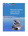
Network Camera is not only a high-performance web-ready camera but also can be
part of a flexible surveillance system. It is the user’s responsibility to ensure that the
operation of such devices is legal before installing this unit for its intended use.
It is important to first verify that all contents received are complete according to the
list in the "Package Contents" chapter. Take notice of the warnings in “Quick
installation guide” before the Network Camera is installed, then carefully read and
follow the instructions in the “Installation” chapter to avoid damages due to faulty
assembly and installation. This also ensures the product is used properly as
intended.
The Network Camera is a network device and its use should be straightforward for
those who have basic network knowledge. The “Troubleshooting” chapter in the
Appendix provides remedies to the most common errors in set up and configuration.
You should consult this chapter first if you run into a system error.
The Network Camera is designed for various applications including video sharing,
general security/surveillance, etc. The “How to Use” chapter suggests ways to best
utilize the Network Camera and ensure proper operations. For the creative and
professional developers, the "URL Commands of The Network Camera" chapter
serves to be a helpful reference to customize existing homepages or integrating with
the current web server.
For paragraphs preceded by the reader should use caution to understand
completely the warnings. Ignoring the warnings may result in serious hazards o
r
injuries.
T: 886-2-82455282
F: 886-2-82455532

- 2 -
www.vivotek.com
Table of Contents
Before You Use This Product 1
Package Contents 4
Installation 5
Hardware Installation 5
Software Installation 6
Initial Access to the Network Camera 8
Initial Access to the Network Camera 9
Check Network Settings 9
Add Password to prevent Unauthorized Access 9
How to Use 10
Authentication 10
Installing Plug-in 11
Primary User’s Capabilities 12
Main Screen with Camera View 12
Client Settings 15
Administrator’s Capabilities 18
Fine-tuning for Best Performance 18
Opening Accounts for New Users 20
Building a multimedia web attraction site 21
Building a security application 25
Software revision upgrade 28
Definitions in Configuration 29
System parameters 30
User group administration 31
Network settings 32
SMTP 32
FTP 33
HTTP 34
Streaming 34
Audio/Video Codec Parameters 35
Audio Parameters 35
T: 886-2-82455282
F: 886-2-82455532

- 3 -
www.vivotek.com
Video Parameters 35
Motion detection 37
Application setup 38
Weekly Schedule 38
Event operation 38
Sequential operation 39
Camera Control 40
UPnP and DDNS Settings 42
Remote controller 43
Viewing system parameters 44
Factory default 44
Appendix 45
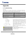
A. Troubleshooting 45
B. Frequently asked questions 46
C. URL commands of the Network Camera 49
Capture update Snapshot of JPEG image 49
Query status of the digital input 49
Drive the digital output 49
Restore factory default settings 49
Restart system 50
Page URL 51
System resource URL 51
General format of command URL 52
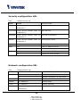
System configuration URL 52
Security configuration URL 53
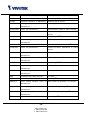
Network configuration URL 53
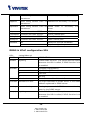
DDNS & UPnP configuration URL 55
Audio/Video configuration URL 56
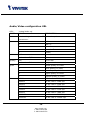
Camera control URL 57
Image quality configuration URL 58
Application configuration URL 58
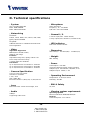
D. Technical specifications 60
T: 886-2-82455282
F: 886-2-82455532

- 4 -
www.vivotek.com
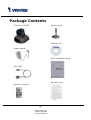
Package Contents
PT3112 or PT3122
Power adapter
A/V Cable
Remote Controller
Camera stand
Software CD
Quick installation guide
Warranty card
T: 886-2-82455282
F: 886-2-82455532

- 5 -
www.vivotek.com
T: 886-2-82455282
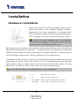
Installation
Hardware Installation
Please verify that your product package contains all the
accessories listed in the foregoing Package Contents.
Depending on the user’s application, an Ethernet cable
may be needed. The Ethernet cable should meet the specs
of UTP Category 5 and not exceed 100 meters in length.
Connect the power adapter jack to the Network
Camera before plugging in to the power socket. This will
reduce the risk of accidental electric shock.
Upon powering up, the device runs through a self-test procedure and the front LEDs will
blink between green and red a few times. If self-test passes, the LEDs will shut off and the
Network Camera will be on stand-by and ready for software installation. If self-test fails the
red LED will blink several times. Refer to Appendix A for troubleshooting.
The Network Camera provides a general I/O terminal block with one digital input and one
relay switch for device control. Pin 1 and Pin 2 can be connected to an external sensor
device and the state of voltage can be monitored from the initial state 'LOW'. The relay
switches Pin 3 and Pin 4 can be used to turn on or off an external device.
Consult with the dealer of the peripherals for correct installation.
1 DI+ INPUT (Max. 50mA, 12VDC)
2 DI- INPUT (Initial state of DI is Low)
3 SW_COMMON OUTPUT (open from SW_OPEN at initial state)
4 SW_NOPEN OUTPUT (Max. 1A, 24VDC or 0.5A, 125VAC)
F: 886-2-82455532

- 6 -
www.vivotek.com
T: 886-2-82455282
Software Installation
In this manual, "User" refers to whoever has access to the Network Camera, and
"Administrator" refers to the person who can configure the Network Camera and grant
user access to the camera.
At the end of the hardware installation, the Administrator must place the product
software CD into the CD-ROM drive of the PC running in MS Windows. An auto-run
program will pop up (If the program is not on auto-run, go to the root directory of the
software CD and click on “autorun.exe”).
Click on the IP installer and run Vivotek’s Installation program.
F: 886-2-82455532

- 7 -
www.vivotek.com
T: 886-2-82455282
Upon IP installer’s start up, a searching box will pop
up. This program searches for Vivotek’s product on
the same LAN:
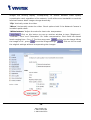
After searching the LAN, the main window of IP installer will pop up.
The IP addresses shown in the
"Current IP Address" field reflect
those on the local network. They
may be from the DHCP server. I
there is no DHCP server, the camera
will try to find a free IP address (this
takes from 15 second to 3 minutes,
depending on the LAN status). The
method of finding IP address i
seeking from 192.168.0.99, to
192.168.0.254. If any of the
address inside this range is free, the
Network Camera will be assigned to
this IP, and its subnet mask would
be 255.255.255.0. If none of the
addresses is free, the Network
Camera will try the range from
192.168.0.2 to 192.168.0.98. After an IP address is assigned to the camera, the
“Activity” status LED blinks.
f
s
F: 886-2-82455532

- 8 -
www.vivotek.com
T: 886-2-82455282
The Vivotek’s new uPnP function
will always assign an IP address
for the Network Camera. The
Administrator can click on button
“Link to selected device” to
connect the I.E. to the camera.
If the camera is not on the IP
installer list, click on the “Search”
button to search for the camera
on the LAN.
For the series number in the “Serial
Number” field, please check the label on the
bottom of the camera.
F: 886-2-82455532

- 9 -
www.vivotek.com
T: 886-2-82455282
Initial Access to the Network Camera
Check Network Settings
The Network Camera can be connected either before or immediately after software
installation onto the Local Area Network. The Administrator should complete the
network settings on the configuration page, including the correct subnet mask and IP
address of gateway and DNS. Ask your network administrator or Internet service
provider for the detail information. By default the Network Camera requires the
Administrator to run installation every time it reboots. If the network settings are to
remain unchanged, disable the Install option. Refer to “Network settings” on the
System Configuration page for details. If any setting is entered incorrectly and cannot
proceed to setting up the Network Camera, restore the factory settings following the
steps in the “Troubleshooting” chapter of the Appendix.
Add Password to prevent Unauthorized Access
The default Administrator’s password is blank and the Network Camera initially will not
ask for any password. The Administrator should immediately implement a new
password as a matter of prudent security practice. Once the Administrator’s password
is saved, the Network Camera will ask for the user’s name and password before each
access. The Administrator can set up a maximum of twenty (20) user accounts. Each
user can access the Network Camera except to perform system configuration. Some
critical functions are exclusive for the Administrator, such as system configuration,
user administration, and software upgrades. The user name for the Administrator is
permanently assigned as “root”. Once the password is changed, the browser will
display an authentication window to ask for the new password. Once set, there is
no provision to recover the Administrator’s password. The only option is to
restore to the original factory default settings.
F: 886-2-82455532

- 10 -
www.vivotek.com
T: 886-2-82455282
How to Use
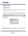
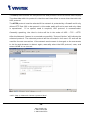
Authentication
After opening the Web browser and typing in the URL of the Network Camera, a
dialogue window pops up to request a username and password. Upon successful
authentication, the following figure is displayed.
The foreground is the login window and the background shows the message if
authentication fails. The user may check the option box to save the password for future
convenience. This option is not available to the Administrator for obvious reason.
F: 886-2-82455532

- 11 -
www.vivotek.com
T: 886-2-82455282
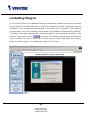
Installing Plug-in
For the initial access to the Network Camera in Windows, the web browser may prompt
for permission to install a new plug-in that is the Network Camera. Permission request
depends on the Internet security settings of the user’s PC or notebook. If the highest
security level is set, the computer may prohibit any installation and execution attempt.
This plug-in has been registered for certificate and is used to display the video in the
browser. Users may click on
to proceed. If the web browser does not allow the
user to continue to install, check the Internet security option and lower the security
levels or contact your IT or networking supervisor for help.
F: 886-2-82455532

- 12 -
www.vivotek.com
T: 886-2-82455282
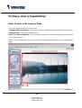
Primary User’s Capabilities
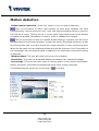
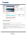
Main Screen with Camera View
The main page layout has three parts:
Configuration functions: The camera can be configured using these user interfaces.
Camera View: What the camera sees.
Pan/Tilt control buttons: These buttons provide a command interface to control the
aim of the camera.
Click on the configuration link to the left of the image window to enter the configuration
page.
F: 886-2-82455532

- 13 -
www.vivotek.com
T: 886-2-82455282
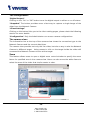
The Configuration:
“Digital Output”
Clicking on the “On” or “Off” button turns the digital output to either on or off status.
“Snapshot” The button provides users a fast way to capture a single image of the
video from the Network Camera.
“Client Settings”
Clicking on this button links you to the client setting pages, please check the following
session for more details.
“Configuration” Only the Administrator can access camera configurations.
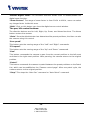
The camera view:
The information bar at the top of the camera view shows the connection type to the
Network Camera and the current date/time.
The camera view provides not only the live video, but also a way to aim the Network
Camera to different target. Using mouse to click on the target inside the video will
command the Network Camera to aim at the target.
Zoom
This feature allows users to open a digital zoom control window to specify the zoom
factor for specified area in the camera view. Users can also move the white frame to
select the area of the video that she/he wants to view.
F: 886-2-82455532

- 14 -
www.vivotek.com
T: 886-2-82455282
“Disable digital zoom” The checkbox selection allows users to disable/enable the
digital zoom function.
“Zoom Factors” The range of zoom factor is from 100% to 400%, users can select
any integer factor inside this area.
“Hide” Click on this button can close the digital zoom control window.
The pan/tilt control buttons:
The direction buttons are for Left, Right, Up, Down, and Home functions. The Home
button centers the camera.
“Go to” Once the Administrator has determined the preset positions; the User can aim
the camera using this control.
“Pan speed”
This button sets the moving range of the “Left” and “Right” commands.
“Tilt speed”
This button sets the moving range of the “Up” and “Down” commands.
“Pan”
This button commands the camera to pan from the current position to the left-most
and then to the right-most position. After panning, the camera returns to the original
position.
“Patrol”
This button commands the camera to patrol between the preset positions on the Patrol
List, which can be modified on the “Camera control page”. After one patrol cycle, the
camera returns to the original position.
“Stop” This stops the “Auto Pan” command or “Auto Patrol” command.
F: 886-2-82455532

- 15 -
www.vivotek.com
T: 886-2-82455282
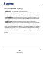
Client Settings
At the initial access to the “Connection type” page in Windows, the web browser will
ask for a new plug-in installation, the plug-in being the Network Camera. This plug-in
has been registered for certification and can be used to change the parameters at the
client’s site. The user may click on
to install the plug-in. If the web browser
does not allow the user to complete the installation, check the Internet security to
lower the security level or contact your IT or networking supervisor.
There are two settings for the Client site. One is “Media Option” for the User to
determine if audio should be muted. The other is “Protocol Option” which allows
choices on connection protocol between client and server. There are three protocol
choices to optimize your usage - UDP, TCP and HTTP.
The UDP protocol allows for more real-time audio and video streams. However, some
packets may be lost due to network burst traffic and images may be obscured.
F: 886-2-82455532

- 16 -
www.vivotek.com
T: 886-2-82455282
The TCP protocol allows for less packet loss and produce a more accurate video display.
The downside with this protocol is that the real-time effect is worse than that with the
UDP protocol.
The HTTP protocol must be selected if the network is protected by a firewall and it only
allows HTTP Port (80) to be opened. In this mode, audio will not be sent and only video
is operational. If no special need is required, UDP protocol is recommended.
Generally speaking, the client’s choice will be in the order of UDP → TCP → HTTP.
After the Network Camera is connected successfully, “Protocol Option” will indicate the
selected protocol. The selected protocol will be recorded in the user's PC and will be
used for the next connection. If the network environment is changed, or the user wants
to let the web browser to detect again, manually select the UDP protocol, save, and
return HOME to re-connect.
<url>
http://<Network Camera>/protocol.html
F: 886-2-82455532

- 17 -
www.vivotek.com
T: 886-2-82455282
<Network Camera> is the domain name or the original IP address of the Network
Camera.
F: 886-2-82455532

- 18 -
www.vivotek.com
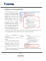
T: 886-2-82455282
Administrator’s Capabilities
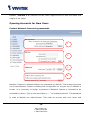
Fine-tuning for Best Performance
There are a few choices the Administrator is allowed to maximize the capabilities of the
Network Camera. Best performance generally equates to the fastest image refresh
rate with the best video quality, and at the lowest network bandwidth as possible. The
three factors, “Maximum frame rate”, “Fix bit rate”, and “Fix quality” on the Video
Configuration page, are correlative to allow for achieving the best performance
possible.
For Best Real-time Video Images
To achieve good real-time visual effect, the network bandwidth should be large enough
to allow a transmission rate of greater than 20 image frames per second. If the
broadband network is over 1 Mbps, set the “Fix bit rate” to 1000Kbps or 1200Kbps, or
set “Fix quality” at the highest quality. The maximum frame rate is 25 fps in a 50Hz
F: 886-2-82455532

- 19 -
www.vivotek.com
T: 886-2-82455282
system and 30 fps in a 60Hz system. If your network bandwidth is more than 384Kbps,
you can fix the bit rate according to your bandwidth and set the maximum frame rate
to 25 fps or 30 fps. If you are shooting fast-moving images, you may want to slow the
maximum frame rate down to 20 fps in order to lower the rate of data transmission.
This allows for better video quality and the human eyes cannot readily detect the
differences between those of 20, 25, or 30 frames per second. If your network
bandwidth is below 384 Kbps, set the “Fix bit rate” according to your bandwidth and try
to get the best performance by fine-tuning with the “Maximum frame rate”. In a slow
network, greater frame rate results in blur images. Another work-around is to choose
“Half” in the “Size” option for better images, or “Halfx2” for a larger image view. Video
quality performance will vary somewhat due to the number of users viewing on the
network; even when the parameters have initially been finely tuned. Performance will
also suffer due to poor connectivity because of the network’s burst constraint.
Only Quality Images Will Do
To have the best video quality, you should set “Fix quality” at “Detailed” or “Excellent”
and adjust the “Maximum frame rate” to match your network’s bandwidth. If your
network is slow and you receive “broken” pictures, go to the TCP protocol in
“Connection type” and choose a more appropriate mode of transmission. The images
may suffer a time delay due to a slower connection. The delay will also increase with
added number of users.
Somewhere Between Real-time and Clear Images
If you have a broadband network, set “Fix quality” at ”Normal” or better, rather than
setting “Fix bit rate”. You can also fix the bandwidth according to your actual network
speed and adjust the frame rate. Start from 30 fps down for best results but not
below 15 fps. If the image qualities are not improved, select a lower bandwidth
setting.
Viewing Double size image
The Network Camera not only provide standard CIF/SIF format video, but also provide
4CIF/4SIF format video. For selecting “Double” video size, the video from the
Network Camera can provide more details, but less frame-rate (up to 10 frames/sec).
F: 886-2-82455532
Page is loading ...
Page is loading ...
Page is loading ...
Page is loading ...
Page is loading ...
Page is loading ...
Page is loading ...
Page is loading ...
Page is loading ...
Page is loading ...
Page is loading ...
Page is loading ...
Page is loading ...
Page is loading ...
Page is loading ...
Page is loading ...
Page is loading ...
Page is loading ...
Page is loading ...
Page is loading ...
Page is loading ...
Page is loading ...
Page is loading ...
Page is loading ...
Page is loading ...
Page is loading ...
Page is loading ...
Page is loading ...
Page is loading ...
Page is loading ...
Page is loading ...
Page is loading ...
Page is loading ...
Page is loading ...
Page is loading ...
Page is loading ...
Page is loading ...
Page is loading ...
Page is loading ...
Page is loading ...
Page is loading ...
Page is loading ...
-
 1
1
-
 2
2
-
 3
3
-
 4
4
-
 5
5
-
 6
6
-
 7
7
-
 8
8
-
 9
9
-
 10
10
-
 11
11
-
 12
12
-
 13
13
-
 14
14
-
 15
15
-
 16
16
-
 17
17
-
 18
18
-
 19
19
-
 20
20
-
 21
21
-
 22
22
-
 23
23
-
 24
24
-
 25
25
-
 26
26
-
 27
27
-
 28
28
-
 29
29
-
 30
30
-
 31
31
-
 32
32
-
 33
33
-
 34
34
-
 35
35
-
 36
36
-
 37
37
-
 38
38
-
 39
39
-
 40
40
-
 41
41
-
 42
42
-
 43
43
-
 44
44
-
 45
45
-
 46
46
-
 47
47
-
 48
48
-
 49
49
-
 50
50
-
 51
51
-
 52
52
-
 53
53
-
 54
54
-
 55
55
-
 56
56
-
 57
57
-
 58
58
-
 59
59
-
 60
60
-
 61
61
-
 62
62


Vivotek PT3112 User manual
- Category
- Video servers/encoders
- Type
- User manual
Ask a question and I''ll find the answer in the document
Finding information in a document is now easier with AI
