Page is loading ...

M-2700-SRevised 09-01-86
Vane Motors
M2-200, M2-300, M2-400
and M2-500 Series
Overhaul Manual
Vickers
®
Vane Motors

2
Table of Contents
Section Page
I. Introduction
A. Purpose of Manual 3. . . . . . . . . . . . . . . . . . . . . . . . . . . . . . . . . . . . . . . . . . . . . . . . . . . . . . . . . . . . . . . . . . . . . . . . . . .
B. General Information 3. . . . . . . . . . . . . . . . . . . . . . . . . . . . . . . . . . . . . . . . . . . . . . . . . . . . . . . . . . . . . . . . . . . . . . . . . .
II. Description
A. General 4. . . . . . . . . . . . . . . . . . . . . . . . . . . . . . . . . . . . . . . . . . . . . . . . . . . . . . . . . . . . . . . . . . . . . . . . . . . . . . . . . . . .
B. Assembly and Construction 4. . . . . . . . . . . . . . . . . . . . . . . . . . . . . . . . . . . . . . . . . . . . . . . . . . . . . . . . . . . . . . . . . . .
C. S2 Motors 4. . . . . . . . . . . . . . . . . . . . . . . . . . . . . . . . . . . . . . . . . . . . . . . . . . . . . . . . . . . . . . . . . . . . . . . . . . . . . . . . . .
D. Mounting and Drive Connections 4. . . . . . . . . . . . . . . . . . . . . . . . . . . . . . . . . . . . . . . . . . . . . . . . . . . . . . . . . . . . . . .
E. Application
III. Principles of Operation
A. General 5. . . . . . . . . . . . . . . . . . . . . . . . . . . . . . . . . . . . . . . . . . . . . . . . . . . . . . . . . . . . . . . . . . . . . . . . . . . . . . . . . . . .
B. Cartridge Action 5. . . . . . . . . . . . . . . . . . . . . . . . . . . . . . . . . . . . . . . . . . . . . . . . . . . . . . . . . . . . . . . . . . . . . . . . . . . . .
C. Hydraulic Balance 5. . . . . . . . . . . . . . . . . . . . . . . . . . . . . . . . . . . . . . . . . . . . . . . . . . . . . . . . . . . . . . . . . . . . . . . . . . .
D. Rocker Arms 5. . . . . . . . . . . . . . . . . . . . . . . . . . . . . . . . . . . . . . . . . . . . . . . . . . . . . . . . . . . . . . . . . . . . . . . . . . . . . . . .
E. Pressure Plate 5. . . . . . . . . . . . . . . . . . . . . . . . . . . . . . . . . . . . . . . . . . . . . . . . . . . . . . . . . . . . . . . . . . . . . . . . . . . . . .
F. S2 Motors 6. . . . . . . . . . . . . . . . . . . . . . . . . . . . . . . . . . . . . . . . . . . . . . . . . . . . . . . . . . . . . . . . . . . . . . . . . . . . . . . . . .
IV. Installation and Operating Instructions
A. Installation Drawings 6. . . . . . . . . . . . . . . . . . . . . . . . . . . . . . . . . . . . . . . . . . . . . . . . . . . . . . . . . . . . . . . . . . . . . . . . .
B. Drive Connections 6. . . . . . . . . . . . . . . . . . . . . . . . . . . . . . . . . . . . . . . . . . . . . . . . . . . . . . . . . . . . . . . . . . . . . . . . . . .
C. Shaft Rotation 7. . . . . . . . . . . . . . . . . . . . . . . . . . . . . . . . . . . . . . . . . . . . . . . . . . . . . . . . . . . . . . . . . . . . . . . . . . . . . . .
D. Hydraulic Tubing 7. . . . . . . . . . . . . . . . . . . . . . . . . . . . . . . . . . . . . . . . . . . . . . . . . . . . . . . . . . . . . . . . . . . . . . . . . . . . .
E. Hydraulic Fluid Recommendations 7. . . . . . . . . . . . . . . . . . . . . . . . . . . . . . . . . . . . . . . . . . . . . . . . . . . . . . . . . . . . .
F. Overload Protection 8. . . . . . . . . . . . . . . . . . . . . . . . . . . . . . . . . . . . . . . . . . . . . . . . . . . . . . . . . . . . . . . . . . . . . . . . . .
G. Port Positions 8. . . . . . . . . . . . . . . . . . . . . . . . . . . . . . . . . . . . . . . . . . . . . . . . . . . . . . . . . . . . . . . . . . . . . . . . . . . . . . .
V. Service, Inspection and Maintenance
A. Service Tools 8. . . . . . . . . . . . . . . . . . . . . . . . . . . . . . . . . . . . . . . . . . . . . . . . . . . . . . . . . . . . . . . . . . . . . . . . . . . . . . . .
B. Inspection 8. . . . . . . . . . . . . . . . . . . . . . . . . . . . . . . . . . . . . . . . . . . . . . . . . . . . . . . . . . . . . . . . . . . . . . . . . . . . . . . . .
C. Adding Fluid to the System 9. . . . . . . . . . . . . . . . . . . . . . . . . . . . . . . . . . . . . . . . . . . . . . . . . . . . . . . . . . . . . . . . . . . .
D. Lubrication 9. . . . . . . . . . . . . . . . . . . . . . . . . . . . . . . . . . . . . . . . . . . . . . . . . . . . . . . . . . . . . . . . . . . . . . . . . . . . . . . . . .
E. Replacement Parts 9. . . . . . . . . . . . . . . . . . . . . . . . . . . . . . . . . . . . . . . . . . . . . . . . . . . . . . . . . . . . . . . . . . . . . . . . . . .
F. Product Life 9. . . . . . . . . . . . . . . . . . . . . . . . . . . . . . . . . . . . . . . . . . . . . . . . . . . . . . . . . . . . . . . . . . . . . . . . . . . . . . . . .
G. Troubleshooting 9. . . . . . . . . . . . . . . . . . . . . . . . . . . . . . . . . . . . . . . . . . . . . . . . . . . . . . . . . . . . . . . . . . . . . . . . . . . . .
VI. Overhaul
A. General 9. . . . . . . . . . . . . . . . . . . . . . . . . . . . . . . . . . . . . . . . . . . . . . . . . . . . . . . . . . . . . . . . . . . . . . . . . . . . . . . . . . . .
B. Disassembly 9. . . . . . . . . . . . . . . . . . . . . . . . . . . . . . . . . . . . . . . . . . . . . . . . . . . . . . . . . . . . . . . . . . . . . . . . . . . . . . . .
C. Inspection and Repair 10. . . . . . . . . . . . . . . . . . . . . . . . . . . . . . . . . . . . . . . . . . . . . . . . . . . . . . . . . . . . . . . . . . . . . . .
D. Reassembly 10. . . . . . . . . . . . . . . . . . . . . . . . . . . . . . . . . . . . . . . . . . . . . . . . . . . . . . . . . . . . . . . . . . . . . . . . . . . . . . .
VII. Testing 10. . . . . . . . . . . . . . . . . . . . . . . . . . . . . . . . . . . . . . . . . . . . . . . . . . . . . . . . . . . . . . . . . . . . . . . . . . . . . . . . . . . . . . . . . .
VIII. Design Changes
A. Change From –11 to –12 Design 12. . . . . . . . . . . . . . . . . . . . . . . . . . . . . . . . . . . . . . . . . . . . . . . . . . . . . . . . . . . . . .
B. Change From –12 to –13 Design 12. . . . . . . . . . . . . . . . . . . . . . . . . . . . . . . . . . . . . . . . . . . . . . . . . . . . . . . . . . . . . .

3
Section I – Introduction
A. Purpose of Manual
This manual has been prepared to assist the users of
Vickers M2 series balanced vane type motors in properly
installing, maintaining and repairing their units. The vane
motors are described in detail and their theory of operation is
discussed, in addition to instructions for installation,
maintenance and overhaul.
B. General Information
Related Publications – Service parts information and instal-
lation dimensions are not contained in this manual. The parts
catalogs and installation drawings listed in Table 1 are avail-
able from Vickers sales engineers.
Model Codes – There are many variations within each basic
model series, which are covered by variables in the model
code. A complete breakdown of the codes covering these units
are in Table 2. Service inquiries should always include the
complete unit model number as stamped on the motor cover.
Motors of the -13 design will be referred to in the discussion
which follows in Sections II through VII, but information is
essentially the same for the -11 and -12 designs. Section VIII
describes the differences between the three designs.
Model
Parts Drawing Installation Drawing
25M, 26M -20 M-2741-S
35M, 36M -20 M-2742-S
MB-185
45M, 46M -20 M-2743-S
MB
-
18
5
50M, 51M -20 M-2744-S
Table 1. Parts and Installation Drawings
9
5
2
2 4 67891
Vane Type Motor
1
3
3
Reversible
Series
4
Mounting
Body Type
Port Positions (See Figure 6)
5
0 – None
4 – Foot
5 – Flange
1 – Standard with Threaded
Connections
3 – Face Mounted with Threaded
Connections
4 – Face Mounted with Flange
Connections
2 – Small
3 – Medium
4 – Large
5 – Extra Large
10
Design
10
11
Torque in Inch Pounds/100 psi
6
7
Shaft
1 – Straight with Square Key
3 – Threaded with Woodruff Key
6 – Straight with Woodruff Key
9 – Splined
Flange Connections
8
11
Special Features
S2 – Vane Base Feed
Table 2. Model Code Breakdown

4
Section II – Description
A. General
All motors covered in this manual are basically identical in
construction. Variables in the model numbers cover different
sizes, mounting and port connections. Motors are of three
basic sizes: small series M2-200, intermediate series M2-300
and large series M2-400 and M2-500. Sizes are progres-
sively rated in torque.
Motors are designed for installation in a hydraulic circuit
requiring rotary mechanical power. Their operating character-
istics are of the variable horsepower class in that horsepower
output is in proportion to rpm so long as operating pressure
is constant. These motors can be used for reversing service
and can be stalled under load without damage.
Construction is such that the output capacity can be varied
(within a series) to suit the particular needs of the user. This
is accomplished by changing the ring and rotor sub-
assembly (Section VI).
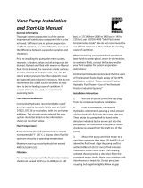
B. Assembly and Construction
Basic motor construction is illustrated in Figure 1. The unit
consists principally of a body, cover, drive cartridge, pressure
plate, drive shaft and bearings. The cartridge consists of a
ring, rotor, twelve vanes and twelve rocker arms. The vanes
slide radially in the rotor slots to follow the cam contour of the
ring. Rocker arms hold the vanes out against the ring.
The rotor is splined to the output shaft. The shaft is sup-
ported by two bearings.
The cartridge is adjoined by the pressure plate on one side
and the body on the other. The pressure plate is housed in
the cover and loaded against the cartridge by a spring
washer (not visible in Figure 1). The cover and body each
incorporate an oil port used as system connections to direct
oil to and from the motor.
Locating pins position the ring with respect to the pressure
plate and body. The shaft seal prevents leakage of oil out of
the system at the shaft and the entry of air into the system.
C. S2 Motors
These motors differ from standard units in that the vanes are
held out against the ring by oil pressure. Pressure is fed in
through a connection in the cover and through a special
pressure plate. Rocker arms are not used.
D. Mounting and Drive Connections
Units can be either face or foot mounted. The rugged two
bearing construction permits the motors to be used in direct
or indirect drive installations.
E. Applications
For motor ratings and applications, consult a Vickers applica-
tion engineer.
Pressure Plate
Vane
Rotor
Rocker Arm
Bearing
Snap Ring
Key
Shaft
Body
Ring
Cover
Seal
Bearing
Figure 1. Cutaway View of Vane Motor

5
Section III – Principles of Operation
A. General
Rotation of the motor shaft is caused by fluid flow
through the motor exerting a force against the vanes.
This force is in effect tangential to the rotor and causes
the rotor to turn, carrying the motor shaft with it.
If fluid is directed into the motor from the body port (see
Figure 2), shaft rotation, as viewed from the head end, is
counterclockwise. When the cover port is used for the inlet,
rotation clockwise as viewed from the cover end. Changing
the direction of fluid flow thus changes the direction of motor
rotation. This is usually accomplished by the use of a
suitable directional control valve. With either port open to
pressure, the other port becomes the return port.
As viewed from cover end:
Rotation is counterclockwise when body port is inlet.
Rotation is clockwise when cover port is inlet.
Kidney Slot
Cover End View
Ring
Vane
Rotor
From Body Port
To Cover
Port
1
2
3
4
9
A
A1
B
B1
Figure 2.
B. Cartridge Action
High pressure oil entering the body port (see Figure 3) is
divided by internal coring and is directed into chambers
between the vanes through kidney slots A and A1 (see
Figure 2). The chambers between vane 2 and vane 3 are
supplied with high pressure oil from port A. The chambers
between vane 3 and vane 4 are at a lower pressure because
they are open to discharge port B. Counterclockwise rotation
of the rotor and vane assembly results from the difference in
pressure across vane 3. This action is duplicated on vane 9.
As any two successive vanes pass the A and A1 slots,
fluid between them is trapped and carried to the B and
B1 slots. Here, the distance between the rotor and ring
is decreasing, and the fluid flows into low pressure
kidney slots and is directed through internal coring to
tank.
Wave Washer
Cover
Drive Cartridge
Seat Seat
Body
Shuttle
Valve
Figure 3.
It can be readily seen from Figure 2 that if the direction
of flow is reversed, B and B1 will become pressure
chambers and the direction of shaft rotation will be
reversed.
C. Hydraulic Balance
Regardless of whether A and A1 or B and B1 are high
pressure chambers, equal pressure will always be present in
any two chambers 180 degrees apart. Thus, hydraulic loads
against the shaft cancel each other out and the unit is in
hydraulic balance.
D. Rocker Arms
Rocker arms (Figure 4) are required to hold the vanes
outward against the ring until system pressure builds up.
They also aid in keeping the vanes against the ring when the
pressure is at a high level (see E. Pressure Plate below).
These arms move about a pivot pin attached to the rotor. The
ends of each arm support tow vanes 90 degrees apart.
Action is such that as one vane (A) is being forced into its
rotor slot by the ring, the other (B) is forced out by the rocker
arm. Although the arm exerts a certain amount of spring
tension against the vanes, flexing is virtually eliminated by
the rocking action as the arm swivels on its pin.
E. Pressure Plate
The pressure plate serves two purposes. It seals the cover
end of the cartridge against internal leakage and it contains
porting to feed system pressure to the base of the vanes to
hold them out against the ring.

6
Direction
of
Rotation
A
B
Pin
Rocker
Arm
Figure 4.
Before pressure builds up, the pressure plate is held against
the cartridge by a wave (spring) washer (Figure 3). As
system pressure builds up, shuttle valves (1 in Figure 3) in
the pressure plate permit system pressure at the inlet port to
act on the cover end of the pressure plate (chamber A). This
provides a force necessary to overcome the axial separating
forces within the rotating group. Pressure ported by these
shuttle valves is also supplied to the under side of the vanes
(through passage B).
The shuttle valve seals against one or the other of the seats
(depending on the direction of flow) and prevents pressure
fluid from escaping to the outlet port without going through
the cartridge.
F. S2 Motors
In these motors, a pressure 30 psi higher than system
pressure is continually fed to the base of the vanes and to
the front of the pressure plate. This is accomplished by
connecting an external pressure source to the motor cover
and feeding pressure oil directly behind the pressure plate.
Rocker arms are not required, and so a pump rotor is used.
The special pressure plate has porting to feed pressure
under the vanes thus eliminating the need for shuttle valves
(see Figure 5).
Pressure 30 psi higher than system pressure is obtained by
placing a 30 psi check valve between the pump and
directional valve and sampling pressure ahead of the check
valve (see Figure 5).
S2 Connection
No Shuttle Valve
Man Man
30 PSI
PF
A
B
Figure 5.
Section IV – Installation and Operating Instructions
A. Installation Drawings
The installation drawings listed in Table 1 give correct instal-
lation dimensions and instructions.
B. Drive Connections
1. Direct Mounting. Motors so connected are mechani-
cally linked by shaft couplings to the work load. Care should
be exercised in tightening all flange mounting screws to pre-
vent misalignment of shaft connections.
If gaskets are used between mounting flanges of motors and
work load, they should be installed to lay flat and the same
care should be taken in tightening the flange screws evenly.
Shaft connecting devices that are specified for a particular
motor, i.e., keys, collars, or tongued shafts, must be properly
seated to avoid slippage and possible shearing of the shafts.
2. Indirect Mounting. Motors mounted indirectly to
work load employ the use of pulleys and “V” belts or chain
and/or spur gear arrangements. Because of slippage possi-
bilities, it is not recommended that flat belts be used. It is
important to check for correct alignment and excessive belt
tension for any drive coupling arrangement employed on
these motors. This is necessary to prevent excessive side
loads imposed on the drive shaft bearings.

7
C. Shaft Rotation
Motors can be driven in either direction of rotation without
changing their construction or assembly.
D. Hydraulic Tubing
1. All tubing must be thoroughly cleaned before
installation. Recommended methods of cleaning are
sandblasting, wirebrushing and pickling.
2. To minimize flow resistance and the possibility of
leakage, use only as many fittings and connections as
necessary for proper installation.
3. The number of bends in hydraulic lines should be
kept to a minimum to prevent excessive turbulence and
friction of oil flow and to minimize pressure drop in the lines.
Tubing must not be bent too sharply. The recommended
radius for bends is three times the inside diameter of the
tube.
E. Hydraulic Fluid Recommendations
General Data
Oil in a hydraulic system performs the dual function of
lubrication and transmission of power. It constitutes a vital
factor in a hydraulic system and careful selection of it should
be made with the assistance of a reputable supplier. Proper
selection of oil assures satisfactory life and operation of
system components with particular emphasis on hydraulic
motors.
Two Important Factors in Selecting Oil
1. Antiwear Additives – The oil selected must contain the
necessary additives to insure high antiwear characteristics.
2. Viscosity – The oil selected must have proper
viscosity to maintain adequate lubricating film at system
operating temperature.
Suitable Types of Oil
1. Crankcase oil meeting API service classification MS
(most severe). The MS classification is the key to proper selec-
tion of crankcase oils for Mobile hydraulic systems.
2. Antiwear type hydraulic oils produced by all major oil
suppliers and provide the antiwear qualities of MS crankcase
oils. There is no common designation for oils of this type.
3. Certain other types of petroleum oils are suitable for
Mobile hydraulic service if they meet the following provisions:
a. Contain the type and content of antiwear com-
pounding found in MS crankcase oils or have passed pump
tests similar to those used in developing the antiwear type
hydraulic oils.
b. Meet the viscosity recommendations shown in
Table 3. This table summarizes oil types recommended for
use with Vickers equipment in Mobile hydraulic systems by
viscosity and service classification.
Hydraulic System
Operating
Temperature
Range
(Min. to Max.)*
SAE
Viscosity
Designation
American
Petroleum
Institute (API)
Service
Classification
0_F to 180_ F
0_F to 210_ F
50_F to 210_ F
10W
10W-30**
20-20W
MS
MS
MS
*Ambient start up temperature
**See paragraph on Viscosity Index
Table 3
c. Have sufficient chemical stability for Mobile
hydraulic system service.
The following types of oil are suitable if they meet the above
three provisions:
– Series 3 Diesel Engine Oil
– Automatic Transmission Fluid Types A, F and DEXRON
– Hydraulic Transmission Fluid Types C-1 and C-2
Operating Temperature
The temperatures shown in Table 3 are cold start-up to
maximum operating. Suitable start-up procedures must be
followed to insure adequate lubrication during system
warm-up.
Arctic Conditions
Arctic conditions represent a specialized field where
extensive use is made of heating equipment before starting.
If necessary, this, and judicious use of SAE 5W or SAE
5W-20 oil in line with the viscosity guide lines shown in
Table 3, may be used. Dilution of SAE 10W (MS) oil with
maximum of 20% by volume of kerosene or low temperature
diesel fuel is permissible.
During cold start-up, avoid high speed operation of
hydraulic system components until the system is warmed up
to provide adequate lubrication. Operating temperature
should be closely monitored to avoid exceeding a
temperature of 130_F with any of these light weight or
diluted oils.
Other Factors in Selecting an Oil
1. Viscosity – Viscosity is the measure of fluidity. In
addition to dynamic lubricating properties, oil must have
sufficient body to provide adequate sealing effect between
working parts of pumps, valves, cylinders and motors, but
not enough to cause pump cavitation or sluggish valve
action. Optimum operating viscosity of the oil should be
between 80 SSU and 180 SSU. During sustained high tem-
perature operation, viscosity should not fall below 60 SSU.

8
2. Viscosity Index – Viscosity index reflects the way
viscosity changes with temperature. The smaller the viscos-
ity change the higher the viscosity index. The viscosity index
of hydraulic system oil should not be less than 90. Multiple
viscosity oils, such as SAE 10W-30, incorporate additives to
improve viscosity index (polymer thickened). Oils of this type
generally exhibit both temporary and permanent decrease in
viscosity due to the oil shear encountered in the operating
hydraulic system. Accordingly, when such oils are selected, it
is desirable to use those with high shear stability to insure
that viscosity remains within recommended limits.
3. Additives – Research has developed a number of
additive agents which materially improve various characteris-
tics of oil for hydraulic systems. These additives are selected
to reduce wear, increase chemical stability, inhibit corrosion
and depress the pour point. The most desirable oils for
hydraulic service contain higher amounts of antiwear
compounding.
Special Requirements
Where special considerations indicate a need to depart from
the recommended oils or operating conditions, see a Vickers
sales representative.
Cleanliness
Clean fluid is the best insurance for long service life. To
insure your hydraulic system is clean, perform the following
steps.
1. Clean (flush) entire system to remove paint, metal
chips, welding shot, etc.
2. Filter each change of oil to prevent introduction of
contaminants into the system.
3. Provide continuous oil filtration to remove sludge and
products of wear and corrosion generated during the life of
the system.
4. Provide continuous protection of system from entry of
airborne contamination, by sealing the system and/or by
proper filtration of the air.
5. Proper oil filling and servicing of filters, breathers,
reservoirs, etc., cannot be overemphasized.
6. Good system and reservoir design will insure that
aeration of the oil is kept to a minimum.
F. Overload Protection
A relief valve must be installed in the system to limit pressure
to a prescribed maximum. This protects the system
components from excessive pressure. The setting of the
relief valve depends on the work requirements of the system
and the maximum pressure ratings of the system
components.
G. Port Positions
Covers can be assembled in four positions with respect to
bodies as shown in Figure 6. To change the relative location
of the ports, it is necessary only to remove the four cover
bolts and rotate the cover to the desired position. Cover bolts
must be tightened to the torque specified in Figure 7 at
reassembly.
A
B
C
D
Body
Port
Model Code
Cover Port Position
(viewed from cover)
A
B
C
D
Opposite body port
90_ clockwise from body port
In line with body port
90_ counterclockwise from body port
Figure 6.
Section V – Service, Inspection and Maintenance
A. Service Tools
No special tools are required to service these units.
B. Inspection
Periodic inspection of oil condition and tubing connections
can save time-consuming breakdowns and unnecessary
parts replacement. The following should be checked
regularly.
1. All hydraulic connections must be kept tight. A loose
connection in a pressure line will permit the fluid to leak out.
Loose connections in other lines can permit air to be drawn
into the system, resulting in noisy and/or erratic operation.
2. Clean fluid is the best insurance for long service life.
Therefore, the reservoir should be checked periodically for
dirt or other contaminants. If the fluid becomes contaminated,
the system should be thoroughly drained and the reservoir
cleaned before new fluid is added.

9
C. Adding Fluid To The System
When hydraulic fluid is added to replenish the system, it
should always be poured through a fine wire screen (200
mesh or finer).
It is important that the fluid be clean and free of any
substance which could cause improper operation or wear of
the motor or other hydraulic units. Therefore, the use of cloth
to strain the fluid should be avoided to prevent lint from
getting into the system.
D. Lubrication
Internal lubrication is provided by system oil flow.
E. Replacement Parts
Reliable operation throughout the specified operating range
is assured only if genuine Vickers parts are used. Part
numbers are shown in the parts drawings listed in Table 1.
F. Product Life
The longevity of these products is dependent upon
environment, duty cycle, operating parameters and system
cleanliness. Since these parameters vary from application to
application, the ultimate user must determine and establish
the periodic maintenance required to maximize life and
detect potential component failure.
G. Troubleshooting
Table 4 lists the common difficulties experienced with vane
motors and hydraulic systems. It also indicates the probable
causes and remedies for each of the troubles listed.
It should always be remembered that many apparent motor
failures are actually due to the failure of other parts of the
system. The cause of improper operation is best diagnosed
with adequate testing equipment and a thorough understand-
ing of the complete hydraulic system.
TROUBLE
PROBABLE CAUSE REMEDY
Motor not developing sufficient speed or
torque.
Insufficient fluid pressure. Check delivery of motor. Make certain
sufficient hydraulic fluid is available to the
motor. Check motor drive speed.
System overload relief valve set too low. Check pressure and reset relief valve.
Motor requiring excessive torque. Remove motor and check torque
requirements of drive shaft.
Parts of motor cartridge scored due to
excessive pressure or foreign matter in oil.
Remove motor for overhaul.
Motor shaft continuing to rotate when control
is in ‘OFF’ position.
Control valve is not functioning properly. Check control valve for correct spool and
leakage.
Motor turning in wrong direction. Improper port connections at valve plate. Reverse port connections.
Components in system not functioning as
intended.
Check complete system for proper operation.
Table 5. Troubleshooting Chart.
Section VI – Overhaul
A. General
Plug all removed units and cap all lines to prevent the entry
of dirt into the system during shutdown. During disassembly,
pay particular attention to identification of the parts for correct
assembly.
Figure 7 is an exploded view which shows the proper
relationship of the parts for disassembly and assembly.
Figure 1 can be referred to for the correct assembled
relationship.
B. Disassembly
Be certain the unit is not subjected to pressure. Disconnect
and cap all lines before removing the motor from its
mounting. Remove the flanges, screws and o-rings from
M2-500 series motors.
1. Cover End. Place the motor on blocks cover end up.
Remove the four cover screws and washers and lift off the
cover.
Remove the o-ring from the groove in the cover. Remove the
pressure plate and wave washer from the cover and remove
the o-ring from the pressure plate. Do not disassemble the
shuttle valves unless it is necessary to replace them
because of leakage.
Lift off the ring and locating pins. Remove the vanes and
rotor sub-assembly.

10
2. Shaft End. Remove the shaft key and foot mounting
(if used). Remove the snap ring from the body and tap the
cover end of the shaft to force out the shaft and front bearing.
If it is necessary to remove the bearing from the shaft,
support the inner race in an arbor press while pressing the
shaft out.
Remove the oil seal and tap out the inner bearing by
inserting a punch in the cover end of the body.
C. Inspection and Repair
1. Discard the used oil seal and o-rings. Clean all parts
in mineral oil solvent and place them on a clean surface for
inspection.
2. Check for wearing surfaces of the body, pressure
plate, ring and rotor for scoring and excessive wear. Remove
light scoring by lapping. Replace any scored or worn parts.
3. Inspect the vanes for burrs, wear and excessive play
in the rotor slots. Check that vanes do not stick in the rotor
slots. They should move from their own weight when both
rotor and vanes are dry. Replace any defective vanes.
4. Rotate the bearing on the shaft while applying pres-
sure to check for wear, looseness, roughness and pitted or
cracked races.
5. Inspect the oil seal journal on the shaft for scoring or
wear. Replace the shaft if marks cannot be removed by light
lapping.
6. Inspect vane rocker arms for wear and loss of ten-
sion. Replace the rotor sub-assembly if rocker arms are
defective.
D. Reassembly
Coat all parts with clean hydraulic oil to facilitate reassembly
and provide initial lubrication.
1. Shaft End. Place the body on a block, shaft end up.
With a driver which contacts the outer race only, seat the
inner bearing in the body.
Press the shaft seal into the body with the sealing lip facing
the cover end. Use a driver which will apply force only near
the seal periphery. Be certain the seal is firmly in place and is
not cocked.
Press the outer bearing onto the shaft while supporting the
inner race. Cover the shaft splines with tape or a bullet and
install the shaft. The outer bearing must seal firmly in the
body. Install the snap ring which retains the shaft and
bearing. If a mounting bracket is used, it can be installed
now. Tighten the screws evenly to prevent cocking. Install
the shaft key.
3. Cover End. Place the unit on blocks, shaft end
down. Install the o-ring in the groove in the body. Insert both
locating pins in the body face. Place the ring on a clean
smooth surface and insert the rotor inside the ring. Insert the
vanes into the rotor slots, being sure the rocker arm is
properly located behind each individual vane on both sides
of the rotor. The ring, rotor and vanes are now installed on
the locating pins.
NOTE
On -13 design models, pin location makes it
impossible to assemble the ring incorrectly.
When installing the vanes, be certain they rest squarely in
the slots and not on the rocker arms. Check this by turning
the shaft by hand and noting whether any vane extends
beyond the side of the rotor.
Position the pressure plate on the locating pins and install
the pressure plate o-ring and the wave washer. Install the
o-ring in the cover and carefully place the cover over the
plate and wave washer against the ring. Be sure the washer
and o-ring are not dislocated. slowly rotate the cover to its
correct position with relation to the body (see Figure 6).
Install the cover screws and washers and tighten them to the
torque shown in Figure 7. Turn the shaft by hand to be
certain there is no binding.
Section VII – Testing
Vickers Mobile application engineering personnel should be
consulted for test stand circuit requirements and construc-
tion. If test equipment is available, the motor should be
tested at recommended speeds and pressures shown on
installation drawings (see Table 1).

11
Torque Model
(ft. lbs.) Series
70 5 M2-200
100 10 M2-300
150 10 M2-400
250 10 M2-500
Assembly View
M2-500
Series
Only
Screw
Flange
O-ring
Washer
(not used on
M2-200 series)
Cover
O-ring
Wave Washer
Pressure Plate
O-ring
Ring
Pin
Screw
Screw
Flange
O-ring
M2-500
Series
Only
Vane
Rotor
Sub-assembly
O-ring
Body
Bearing
Seal
Shaft
Key
Snap Ring
Bearing
Foot Mounting
Screw
Figure 7.

12
Section VIII – Design Changes
A. Change from -11 to -12 Design
Changes between the -11 and -12 designs were made
to improve pressure distribution (hydraulic balance) in
the motor, strengthen the pressure plate and rocker
arms, permit reversal of the motor without reversing the
ring and improve retention of the rocker arms. Parts
involved in the change were the pressure plate
sub-assembly, rotor sub-assembly and ring and, in
some cases, the body and cover (see Table 5).
Parts are interchangeable between the -11 and -12
design. Customers who wish to incorporate the
improved parts in -11 design motors can do so without
concern.
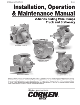
B. Change from -12 to -13 Design
This change increased the size of flow passages and
added eight overpass holes in the ring (see Figure 8).
Also, the ring locating pins were moved 45 degrees.
This makes it impossible to assemble the ring
incorrectly.
Parts involved in the change are listed in Table 5.
Pressure plates, rings and bodies are not
interchangeable (except as a group) because of the pin
location. All other parts are interchangeable.
–12 Design Ring –13 Design Ring
Overpass Holes Added
Pins Relocated
Overpass Holes Added
Figure 8. Change from -12 to -13 Design.
Series
Nomencl t re
Design
Series
Nomencl t re
Design
S
er
i
es
N
omenc
l
ature
-11 -12 -13
S
er
i
es
N
omenc
l
ature
-11 -12 -13
M2-200 Cover
Press plate sub-assy.
Ring 25
Ring 35
Rotor sub-assy. 25
Rotor sub-assy. 35
Body
137569
137570
137576
160795
137573
137573
127225
153998
153570
153766
153765
168439
168440
153698
153998
168450
168419
168418
168439
168440
168417
M2-400 Cover
Press plate sub-assy.
Ring 90
Ring 115
Rotor 90
Rotor 115
Body
Vane Kit
138110
138108
128553
126507
170404
170403
138111
912030
138110
153778
153775
153776
170404
170403
153760
912105
138110
172467
172469
172470
170404
170403
172465
912105
M2-300 Cover
Press plate sub-assy.
Ring 45
Ring 60
Ring 75
Rotor sub-assy. 45
Rotor sub-assy. 60
Rotor sub-assy. 75
Body
137696
137690
126023
126024
126025
137689
137689
137689
137693
137696
153767
153774
153773
153772
170402
170405
170405
153761
137696
172412
172410
172409
172411
170402
170405
170405
172407
M2-500 Cover
Press plate
Ring 150
Ring 200
Rotor 150
Rotor 200
Body
Pin
137281
137420
115768
152381
137325
137325
126676
39780
137281
153783
153784
153785
168598
168599
153790
39780
137281
168601
168596
168597
168598
168599
168595
187259
Table 5. Conversion Data

13
Printed in U.S.A.
Form No. 00-000 Copyright Eaton Corporation, 0000
All rights reserved.
Printed in U.S.A
Eaton Hydraulics
15151 Highway 5
Eden Prairie, MN 55344
Telephone: 612 937-7254
Fax: 612 937-7130
www.eatonhydraulics.com
46 New Lane, Havant
Hampshire PO9 2NB
England
Telephone: (44) 170-548-6451
Fax: (44) 170-548-7110
/