Page is loading ...

Single, Double, Triple,
and Thru-Drive Pumps
Overhaul Service Manual
VMQ125S
VMQ135S
VMQ145S
VMQ125T
VMQ135T
VMQ145
VMQ22525
VMQ23525
VMQ24525
VMQ24535
VMQ3352525
VMQ3453525
Series – 30 Design

Table of Contents
2 EATON Vickers Single, Double, Triple and Thru-drive Pumps Overhaul Service Manual V-PUVN-TS001-E October 2002
Section Page
I. INTRODUCTION
A. Purpose of Manual . . . . . . . . . . . . . . . . . . . . . . . . . . . . . . . . . . . . . . . . . . . . . . . . . . . . . . . . . . . . . . . . . . . . . . . . . . . . . . . . . . . . . . . . . . . . . . . . . . . . . 3
B. General Information . . . . . . . . . . . . . . . . . . . . . . . . . . . . . . . . . . . . . . . . . . . . . . . . . . . . . . . . . . . . . . . . . . . . . . . . . . . . . . . . . . . . . . . . . . . . . . . . . . . . 3
II. DESCRIPTION
A. General . . . . . . . . . . . . . . . . . . . . . . . . . . . . . . . . . . . . . . . . . . . . . . . . . . . . . . . . . . . . . . . . . . . . . . . . . . . . . . . . . . . . . . . . . . . . . . . . . . . . . . . . . . . . . . . 3
B. Model Code . . . . . . . . . . . . . . . . . . . . . . . . . . . . . . . . . . . . . . . . . . . . . . . . . . . . . . . . . . . . . . . . . . . . . . . . . . . . . . . . . . . . . . . . . . . . . . . . . . . . . . . . . . . . 5
C. Assembly and Construction . . . . . . . . . . . . . . . . . . . . . . . . . . . . . . . . . . . . . . . . . . . . . . . . . . . . . . . . . . . . . . . . . . . . . . . . . . . . . . . . . . . . . . . . . . . . . . 8
D. Application . . . . . . . . . . . . . . . . . . . . . . . . . . . . . . . . . . . . . . . . . . . . . . . . . . . . . . . . . . . . . . . . . . . . . . . . . . . . . . . . . . . . . . . . . . . . . . . . . . . . . . . . . . . . 8
III. PRINCIPLES OF OPERATION
A. Pumping Cartridge . . . . . . . . . . . . . . . . . . . . . . . . . . . . . . . . . . . . . . . . . . . . . . . . . . . . . . . . . . . . . . . . . . . . . . . . . . . . . . . . . . . . . . . . . . . . . . . . . . . . . . 8
B. Vane Pressure Feed . . . . . . . . . . . . . . . . . . . . . . . . . . . . . . . . . . . . . . . . . . . . . . . . . . . . . . . . . . . . . . . . . . . . . . . . . . . . . . . . . . . . . . . . . . . . . . . . . . . . 8
C. Hydraulic Balance . . . . . . . . . . . . . . . . . . . . . . . . . . . . . . . . . . . . . . . . . . . . . . . . . . . . . . . . . . . . . . . . . . . . . . . . . . . . . . . . . . . . . . . . . . . . . . . . . . . . . . 9
D. Wafer Plate Operation . . . . . . . . . . . . . . . . . . . . . . . . . . . . . . . . . . . . . . . . . . . . . . . . . . . . . . . . . . . . . . . . . . . . . . . . . . . . . . . . . . . . . . . . . . . . . . . . . . 9
E. Outlet Bodies . . . . . . . . . . . . . . . . . . . . . . . . . . . . . . . . . . . . . . . . . . . . . . . . . . . . . . . . . . . . . . . . . . . . . . . . . . . . . . . . . . . . . . . . . . . . . . . . . . . . . . . . . . 10
IV. INSTALLATION AND OPERATING INSTRUCTIONS
A. Installation Drawings . . . . . . . . . . . . . . . . . . . . . . . . . . . . . . . . . . . . . . . . . . . . . . . . . . . . . . . . . . . . . . . . . . . . . . . . . . . . . . . . . . . . . . . . . . . . . . . . . . 10
B. Mounting and Drive Connections . . . . . . . . . . . . . . . . . . . . . . . . . . . . . . . . . . . . . . . . . . . . . . . . . . . . . . . . . . . . . . . . . . . . . . . . . . . . . . . . . . . . . . . . 10
C. Shaft Rotation . . . . . . . . . . . . . . . . . . . . . . . . . . . . . . . . . . . . . . . . . . . . . . . . . . . . . . . . . . . . . . . . . . . . . . . . . . . . . . . . . . . . . . . . . . . . . . . . . . . . . . . . . 11
D. Piping and Tubing . . . . . . . . . . . . . . . . . . . . . . . . . . . . . . . . . . . . . . . . . . . . . . . . . . . . . . . . . . . . . . . . . . . . . . . . . . . . . . . . . . . . . . . . . . . . . . . . . . . . . 11
E. Hydraulic Fluid Recommendations . . . . . . . . . . . . . . . . . . . . . . . . . . . . . . . . . . . . . . . . . . . . . . . . . . . . . . . . . . . . . . . . . . . . . . . . . . . . . . . . . . . . . . . . 11
F. Overload Protection . . . . . . . . . . . . . . . . . . . . . . . . . . . . . . . . . . . . . . . . . . . . . . . . . . . . . . . . . . . . . . . . . . . . . . . . . . . . . . . . . . . . . . . . . . . . . . . . . . . . 12
G. Port Positions . . . . . . . . . . . . . . . . . . . . . . . . . . . . . . . . . . . . . . . . . . . . . . . . . . . . . . . . . . . . . . . . . . . . . . . . . . . . . . . . . . . . . . . . . . . . . . . . . . . . . . . . . 12
H. Start-Up . . . . . . . . . . . . . . . . . . . . . . . . . . . . . . . . . . . . . . . . . . . . . . . . . . . . . . . . . . . . . . . . . . . . . . . . . . . . . . . . . . . . . . . . . . . . . . . . . . . . . . . . . . . . . . 12
V. INSPECTION AND MAINTENANCE
A. Inspection . . . . . . . . . . . . . . . . . . . . . . . . . . . . . . . . . . . . . . . . . . . . . . . . . . . . . . . . . . . . . . . . . . . . . . . . . . . . . . . . . . . . . . . . . . . . . . . . . . . . . . . . . . . . 13
B. Adding Fluid to the System . . . . . . . . . . . . . . . . . . . . . . . . . . . . . . . . . . . . . . . . . . . . . . . . . . . . . . . . . . . . . . . . . . . . . . . . . . . . . . . . . . . . . . . . . . . . . 13
C. Adjustments . . . . . . . . . . . . . . . . . . . . . . . . . . . . . . . . . . . . . . . . . . . . . . . . . . . . . . . . . . . . . . . . . . . . . . . . . . . . . . . . . . . . . . . . . . . . . . . . . . . . . . . . . . 13
D. Lubrication . . . . . . . . . . . . . . . . . . . . . . . . . . . . . . . . . . . . . . . . . . . . . . . . . . . . . . . . . . . . . . . . . . . . . . . . . . . . . . . . . . . . . . . . . . . . . . . . . . . . . . . . . . . 13
E. Replacement Parts . . . . . . . . . . . . . . . . . . . . . . . . . . . . . . . . . . . . . . . . . . . . . . . . . . . . . . . . . . . . . . . . . . . . . . . . . . . . . . . . . . . . . . . . . . . . . . . . . . . . . 13
F. Product Life . . . . . . . . . . . . . . . . . . . . . . . . . . . . . . . . . . . . . . . . . . . . . . . . . . . . . . . . . . . . . . . . . . . . . . . . . . . . . . . . . . . . . . . . . . . . . . . . . . . . . . . . . . . 13
G. Troubleshooting . . . . . . . . . . . . . . . . . . . . . . . . . . . . . . . . . . . . . . . . . . . . . . . . . . . . . . . . . . . . . . . . . . . . . . . . . . . . . . . . . . . . . . . . . . . . . . . . . . . . . . . 13
VI. OVERHAUL
A. General . . . . . . . . . . . . . . . . . . . . . . . . . . . . . . . . . . . . . . . . . . . . . . . . . . . . . . . . . . . . . . . . . . . . . . . . . . . . . . . . . . . . . . . . . . . . . . . . . . . . . . . . . . . . . . 19
B. Disassembly . . . . . . . . . . . . . . . . . . . . . . . . . . . . . . . . . . . . . . . . . . . . . . . . . . . . . . . . . . . . . . . . . . . . . . . . . . . . . . . . . . . . . . . . . . . . . . . . . . . . . . . . . . 19
C. Drive Reversal . . . . . . . . . . . . . . . . . . . . . . . . . . . . . . . . . . . . . . . . . . . . . . . . . . . . . . . . . . . . . . . . . . . . . . . . . . . . . . . . . . . . . . . . . . . . . . . . . . . . . . . . 19
D. Inspection and Repair . . . . . . . . . . . . . . . . . . . . . . . . . . . . . . . . . . . . . . . . . . . . . . . . . . . . . . . . . . . . . . . . . . . . . . . . . . . . . . . . . . . . . . . . . . . . . . . . . . 20
E. Assembly . . . . . . . . . . . . . . . . . . . . . . . . . . . . . . . . . . . . . . . . . . . . . . . . . . . . . . . . . . . . . . . . . . . . . . . . . . . . . . . . . . . . . . . . . . . . . . . . . . . . . . . . . . . . . . 21

EATON Vickers Single, Double, Triple and Thru-drive Pumps Overhaul Service Manual V-PUVN-TS001-E October 2002 3
Section I —
Introduction
A. Purpose of Manual
Section II –
Description
A. General
Related Publications –
Service parts information and
installation dimensions are not
contained in this manual. The
parts catalogs and installation
drawings are available from
authorized distributors or Eaton
sales engineers.
Model Codes – There are
many variations within each
basic model series, which are
covered by variables in the
model code. A complete
breakdown of the codes
covering these units is in
Tables 1–3 on pages 5–7.
Service inquiries should
always include the complete
unit model number as
stamped on the pump cover.
This manual has been prepared
to assist the users of Eaton’s
high performance VMQ single
pumps in properly installing,
maintaining and repairing their
unit. The single, double, and
triple pumps are described in
detail and their theory of
operation is discussed in
addition to instructions for
installation, maintenance,
and overhaul.
The general series of models
covered are VMQ125S,
VMQ135S, VMQ145S,
VMQ125T, VMQ135T,
VMQ145T, VMQ22525,
VMQ23525, VMQ24525,
VMQ24535, VMQ3352525,
and VMQ3453525. The
information given applies
to the 30-39th Design VMQ.
B. General Information
Pumps in this series are used
to develop hydraulic fluid flow
for the operation of industrial
and mobile equipment. The
positive displacement pumping
cartridges are of the rotary
vane type with shaft side loads
hydraulically balanced. The flow
rate depends on the pump size
and the speed at which it
is driven.
All units are designed so that
the direction of rotation,
pumping capacity and port
positions can be readily
changed to suit particular
applications.
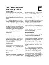
Inlet Cover
Cam Ring
Inlet Hole Thru Ring
Inlet Plate
Under Vane Pin
Inlet Wafer Plate
Rotor
Vane
Outlet Wafer Plate
Outlet Plate
Primary Shaft Seal
Shaft
Secondary Shaft Seal
Shaft Bearing
Outlet Body
Cover/Body O-Ring
Figure 1a. Cutaway View of Typical High Performance VMQ Single Vane Pump

4 EATON Vickers Single, Double, Triple and Thru-drive Pumps Overhaul Service Manual V-PUVN-TS001-E October 2002
Section II —
Description (cont.)
Figure 1b. Cutaway View of Typical High Performance VMQ Double Vane Pump
Figure 1c. Cutaway View of Typical High Performance VMQ Triple Vane Pump
Cover/Housing O-Ring
Outlet Cover Inlet Housing
Housing/Body O-Ring
Outlet Section

Model Code —
Single and Thru-
Drive Pumps
EATON Vickers Single, Double, Triple and Thru-drive Pumps Overhaul Service Manual V-PUVN-TS001-E October 2002 5
Table 1. Model Code Breakdown
* Verify shaft torque ratings meet or exceed input torque requirements
Series designation
VMQ1 – Vane pump single series
Frame size
25 – 10-90 cm
3
/r
(0.62-5.49 in
3
/r)
35 – 90-158 cm
3
/r
(5.49-9.64 in
3
/r)
45 – 140-215 cm
3
/r
(8.54-13.12 in
3
/r)
Pump type
S – Single
T – Thru-drive
(Options at model codes
and must be
specified for thru-drive
units)
Displacement
Frame size 25
010 – 10 cm
3
/r (0.62 in
3
/r)
016 – 16 cm
3
/r (0.98 in
3
/r)
020 – 20 cm
3
/r (1.23 in
3
/r
025 – 25 cm
3
/r (1.58 in
3
/r)
032 – 32 cm
3
/r (1.96 in
3
/r)
040 – 40 cm
3
/r (2.44 in
3
/r)
045 – 45 cm
3
/r (2.75 in
3
/r)
050 – 50 cm
3
/r (3.05 in
3
/r)
063 – 63 cm
3
/r (3.84 in
3
/r)
071 – 71 cm
3
/r (4.33 in
3
/r)
080 – 80 cm
3
/r (4.88 in
3
/r)
090 – 90 cm
3
/r (5.49 in
3
/r)
Frame size 35
090 – 90 cm
3
/r (5.49 in
3
/r)
100 – 100 cm
3
/r (6.10 in
3
/r)
112 – 112 cm
3
/r (6.83 in
3
/r)
125 – 125 cm
3
/r (7.63 in
3
/r)
135 – 135 cm
3
/r (8.24 in
3
/r)
140 – 140 cm
3
/r (8.54 in
3
/r)
158 – 158 cm
3
/r (9.64 in
3
/r)
Frame size 45
140 – 140 cm
3
/r (8.54 in
3
/r)
160 – 160 cm
3
/r (9.76 in
3
/r)
180 – 180 cm
3
/r (10.98 in
3
/r)
195 – 195 cm
3
/r (11.89 in
3
/r)
215 – 215 cm
3
/r (13.12 in
3
/r)
Front flange mounting style
A – (Frame size 25 only)
SAE B 2-bolt
101,60 (4.000) x 9,4
(0.37) pilot
14,4 (0.57) slots on
146,0 (5.75) bolt circle
B – (Frame sizes 35 & 45 only)
SAE C 2-bolt
127,00 (5.000) x 12,4
(0.49) pilot
17,6 (0.69) slots on
181,0 (7.13) bolt circle
C – (Frame size 25 only)
ISO 3019/2 100A2HW
2-bolt
100,00 (3.937) x 9,2
(0.36) pilot
14,1 (0.56) slots on
140,0 (5.51) bolt circle
D – (Frame sizes 35 & 45 only)
ISO 3019/2 125A2HW
2-bolt
125,00 (4.921) x 9,2
(0.36) pilot
18,1 (0.71) slots on
180,0 (7.09) bolt circle
Rear mounting flange
and orientation
Viewed from cover end
of pump (Adapter end for
thru-drive units, model
code = T)
0 – None (non thru-drive)
SAE A
A – In-line with mounting
flange (frame sizes
25 & 45)
B – 90° to mounting flange
(frame sizes 25 & 45)
C – 45° CCW to mounting
flange (frame size 35)
D – 45° CW to mounting
flange (frame size 35)
SAE B
E – In-line with mounting
flange (frame sizes
25 & 45)
F – 90° to mounting flange
(frame sizes 25 & 45)
G – 45° CCW to mounting
flange (frame size 35)
H – 45° CW to mounting
flange (frame size 35)
SAE C
J – In-line with mounting
flange (frame size 35)
K – 90° to mounting flange
(frame size 35)
L – 45° CCW to mounting
flange (frame size 45)
M – 45° CW to mounting
flange (frame size 45)
Input shaft type*
01 – SAE J744 keyed
Frame size 25:
25,40 (1.000)
Frame size 35:
31,75 (1.250)
Frame size 45:
38,10 (1.500)
02 – SAE J744 splined
Frame size 25: B-B
Frame size 35: C
Frame size 45: C-C
03 – ISO 3019/2 keyed
Frame size 25:
25,00 (0.984)
Frame size 35:
32,00 (1.260)
Frame size 45:
40,00 (1.575)
05 – SAE J744 keyed
Frame size 25:
31,75 (1.250)
Frame size 35:
38,10 (1.500)
Frame size 45:
44,45 (1.750)
06 – SAE J744 splined
Frame size 25: C
Frame size 35: C-C
Frame size 45: D
07 – ISO 3019/2 keyed
Frame size 25: 32,00 (1.260)
Frame size 35: 40,00 (1.575)
09 – SAE J744 splined
Frame size 25: B
Frame size 45: C
(Not available on
thru-drive units)
Output shaft coupling
Thru-drive units, model code
= T
00 – None (non thru-drive)
16 – SAE J744 16-4 A-spline
shaft
22 – SAE J744 22-4 B-spline
shaft
25 – SAE J744 25-4 B-B-spline
shaft
32 – SAE J744 32-4 C-spline
shaft (frame sizes
35 & 45 only)
Inlet port type
A – SAE J518 4-bolt split
flange
B – ISO 6162 4-bolt split
flange
Outlet port type
A – SAE J518 4-bolt flange
B – ISO 6162 4-bolt flange
Outlet port position
Viewed from cover end of
pump (Adapter end for
thru-drive units)
A – Opposite inlet port
B – 90° CCW to inlet port
C – In-line with inlet port
D – 90° CW to inlet port
Shaft seal
A – Single, primary
B – Double, secondary
(spring side out)
Recommended for wet
mount applications
Seal type
N – Buna N
V – Viton
W – Buna N with Viton shaft
seal(s)
Shaft rotation
Viewed from shaft end
of pump
L – Left hand (CCW)
R – Right hand (CW)
Special features
00 – None
Paint
0 – None
A – Blue
Customer identification
0 – None
Design code
30 – 30 design
Installation dimensions
remain unchanged for
design numbers 30 to 39
inclusive.
27 28
26
25
23 24
22
21
20
19
18
17
7
15 16
13 14
7
12
11
8 9 10
15 1612
7
5 6
1 2 3 4
VMQ1 ** * *** * * ** ** * * * * * * 00 * 0 30
1 2 3 4 5 6 7 8 9 10 11 12 13 14 15 16 17 18 19 20 21 22 23 24 25 26 27 28

Model Code —
Double Pumps
Table 2. Model Code Breakdown
6 EATON Vickers Single, Double, Triple and Thru-drive Pumps Overhaul Service Manual V-PUVN-TS001-E October 2002
* Verify shaft torque ratings meet or exceed input torque requirements
Series designation
VMQ2 – Vane pump double series
Frame size (front section)
25 – 10-90 cm
3
/r
(0.62-5.49 in
3
/r)
35 – 90-158 cm
3
/r
(5.49-9.64 in
3
/r)
45 – 140-215 cm
3
/r
(8.54-13.12 in
3
/r)
Frame size (rear section)
25 – 10-90 cm
3
/r
(0.62-5.49 in
3
/r)
35 – 90-158 cm
3
/r
(5.49-9.64 in
3
/r)
Pump type
S – Standard
Displacement
(front section)
Frame size 25
010 – 10 cm
3
/r (0.62 in
3
/r)
016 – 16 cm
3
/r (0.98 in
3
/r)
020 – 20 cm
3
/r (1.23 in
3
/r
025 – 25 cm
3
/r (1.58 in
3
/r)
032 – 32 cm
3
/r (1.96 in
3
/r)
040 – 40 cm
3
/r (2.44 in
3
/r)
045 – 45 cm
3
/r (2.75 in
3
/r)
050 – 50 cm
3
/r (3.05 in
3
/r)
063 – 63 cm
3
/r (3.84 in
3
/r)
071 – 71 cm
3
/r (4.33 in
3
/r)
080 – 80 cm
3
/r (4.88 in
3
/r)
090 – 90 cm
3
/r (5.49 in
3
/r)
Frame size 35
090 – 90 cm
3
/r (5.49 in
3
/r)
100 – 100 cm
3
/r (6.10 in
3
/r)
112 – 112 cm
3
/r (6.83 in
3
/r)
125 – 125 cm
3
/r (7.63 in
3
/r)
135 – 135 cm
3
/r (8.24 in
3
/r)
140 – 140 cm
3
/r (8.54 in
3
/r)
158 – 158 cm
3
/r (9.64 in
3
/r)
Frame size 45
140 – 140 cm
3
/r (8.54 in
3
/r)
160 – 160 cm
3
/r (9.76 in
3
/r)
180 – 180 cm
3
/r (10.98 in
3
/r)
195 – 195 cm
3
/r (11.89 in
3
/r)
215 – 215 cm
3
/r (13.12 in
3
/r)
Displacement
(rear section)
Frame size 25
010 – 10 cm
3
/r (0.62 in
3
/r)
016 – 16 cm
3
/r (0.98 in
3
/r)
020 – 20 cm
3
/r (1.23 in
3
/r)
025 – 25 cm
3
/r (1.58 in
3
/r)
032 – 32 cm
3
/r (1.96 in
3
/r)
040 – 40 cm
3
/r (2.44 in
3
/r)
045 – 45 cm
3
/r (2.75 in
3
/r)
050 – 50 cm
3
/r (3.05 in
3
/r)
063 – 63 cm
3
/r (3.84 in
3
/r)
071 – 71 cm
3
/r (4.33 in
3
/r)
080 – 80 cm
3
/r (4.88 in
3
/r)
090 – 90 cm
3
/r (5.49 in
3
/r)
Frame size 35
090 – 90 cm
3
/r (5.49 in
3
/r)
100 – 100 cm
3
/r (6.10 in
3
/r)
112 – 112 cm
3
/r (6.83 in
3
/r)
125 – 125 cm
3
/r (7.63 in
3
/r)
135 – 135 cm
3
/r (8.24 in
3
/r)
140 – 140 cm
3
/r (8.54 in
3
/r)
158 – 158 cm
3
/r (9.64 in
3
/r)
Front flange mounting style
A – (Frame size 25 only)
SAE B 2-bolt
101,60 (4.000) x 9,4
(0.37) pilot
14,4 (0.57) slots on
146,0 (5.75) bolt circle
B – (Frame sizes 35 & 45 only)
SAE C 2-bolt
127,00 (5.000) x 12,4
(0.49) pilot
17,6 (0.69) slots on
181,0 (7.13) bolt circle
C – (Frame size 25 only)
ISO 3019/2 100A2HW
2-bolt
100,00 (3.937) x 9,2
(0.36) pilot
14,1 (0.56) slots on
140,0 (5.51) bolt circle
D – (Frame sizes 35 & 45 only)
ISO 3019/2 125A2HW
2-bolt
125,00 (4.921) x 9,2
(0.36) pilot
18,1 (0.71) slots on
180,0 (7.09) bolt circle
Adapter flange
0 – None (standard
double pump)
Input shaft type*
01 – SAE J744 keyed
Frame size 25:
25,40 (1.000)
Frame size 35:
31,75 (1.250)
Frame size 45:
38,10 (1.500)
02 – SAE J744 splined
Frame size 25: B-B
Frame size 35: C
Frame size 45: C-C
03 – ISO 3019/2 keyed
Frame size 25:
25,00 (0.984)
Frame size 35:
32,00 (1.260)
Frame size 45:
40,00 (1.575)
05 – SAE J744 keyed
Frame size 25:
31,75 (1.250)
Frame size 35:
38,10 (1.500)
Frame size 45:
44,45 (1.750)
06 – SAE J744 splined
Frame size 25: C
Frame size 35: C-C
Frame size 45: D
07 – ISO 3019/2 keyed
Frame size 25:
32,00 (1.260)
Frame size 35:
40,00 (1.575)
09 – SAE J744 Spline
Frame size 45: C
Output shaft coupling
00 – None (standard
double pump)
Inlet port type
A – SAE J518 4-split flange
B – ISO 6162 4-bolt flange
Front outlet port type
A – SAE J518 4-bolt flange
B – ISO 6162 4-bolt flange
Rear outlet port type
A – SAE J518 4-bolt flange
B – ISO 6162 4-bolt flange
Front outlet port position
Viewed from cover end of
pump
A – Opposite inlet port
B – 90° CCW to inlet port
C – In-Line with front
inlet port
D – 90° CW to inlet port
Rear outlet port position
Viewed from cover end
of pump
A – 135° CCW to inlet port
(not available with 2525)
B – 45° CCW to inlet port
(not available with 2525)
C – 45° CW to inlet port
(not available with 2525)
D – 135° CW to inlet port
(not available with 2525)
E – Opposite inlet port
(2525 only)
F – 90° CCW to inlet port
(2525 only)
G – In-line with inlet port
(2525 only)
H – 90° CW to inlet port
(2525 only)
Shaft Seal
A – Single, primary
B – Double, secondary
(spring side out)
Recommended for wet
mount applications
Seal Type
N – Buna-N
V – Viton
W – Buna-N with Viton
shaft seal(s)
Shaft rotation
Viewed from shaft end
of pump
L – Left Hand (CCW)
R – Right Hand (CW)
Special features
00 – None
Paint
O – None
A – Blue
Customer identification
O – None
Design code
30 – 30 design
Installation dimensions
remain unchanged for
design numbers 30 to 39
inclusive.
34 35
33
32
30 31
29
28
27
26
25
24
23
22
20 21
18 19
17
16
13 14 15
10 11 12
9
7 8
5 6
1 2 3 4
VMQ2 ** ** S *** *** * 0 ** 00 * * * * * * * * 00 * 0 30
1 2 3 4 5 6
7 8
9
10 11 12
13 14 15
16
17
18 19 20 21
22
23 24
25
26 27 28
29 30 31 32 33 34 35

Table 3. Model Code Breakdown
EATON Vickers Single, Double, Triple and Thru-drive Pumps Overhaul Service Manual V-PUVN-TS001-E October 2002 7
Model Code —
Triple Pumps
* Verify shaft torque ratings meet or exceed input torque requirements
Series designation
VMQ3 – Vane pump triple series
Frame size (front section)
35 – 90-158 cm
3
/r
(5.49-9.64 in
3
/r)
45 – 140-215 cm
3
/r
(8.54-13.12 in
3
/r)
Frame size
(middle section)
25 – 10-90 cm
3
/r
(0.62-5.49 in
3
/r)
35 – 90-158 cm
3
/r
(5.49-9.64 in
3
/r)
Frame size (rear section)
25 – 10-90 cm
3
/r
(0.62-5.49 in
3
/r)
Displacement
(front section)
Frame size 35
090 – 90 cm
3
/r (5.49 in
3
/r)
100 – 100 cm
3
/r (6.10 in
3
/r)
112 – 112 cm
3
/r (6.83 in
3
/r)
125 – 125 cm
3
/r (7.63 in
3
/r)
135 – 135 cm
3
/r (8.24 in
3
/r)
140 – 140 cm
3
/r (8.54 in
3
/r)
158 – 158 cm
3
/r (9.64 in
3
/r)
Frame size 45
140 – 140 cm
3
/r (8.54 in
3
/r)
160 – 160 cm
3
/r (9.76 in
3
/r)
180 – 180 cm
3
/r (10.98 in
3
/r)
195 – 195 cm
3
/r (11.89 in
3
/r)
215 – 215 cm
3
/r (13.12 in
3
/r)
Displacement
(middle section)
Frame size 25
010 – 10 cm
3
/r (0.62 in
3
/r)
016 – 16 cm
3
/r (0.98 in
3
/r)
020 – 20 cm
3
/r (1.23 in
3
/r
025 – 25 cm
3
/r (1.58 in
3
/r)
032 – 32 cm
3
/r (1.96 in
3
/r)
040 – 40 cm
3
/r (2.44 in
3
/r)
045 – 45 cm
3
/r (2.75 in
3
/r)
050 – 50 cm
3
/r (3.05 in
3
/r)
063 – 63 cm
3
/r (3.84 in
3
/r)
071 – 71 cm
3
/r (4.33 in
3
/r)
080 – 80 cm
3
/r (4.88 in
3
/r)
090 – 90 cm
3
/r (5.49 in
3
/r)
Frame size 35
090 – 90 cm
3
/r (5.49 in
3
/r)
100 – 100 cm
3
/r (6.10 in
3
/r)
112 – 112 cm
3
/r (6.83 in
3
/r)
125 – 125 cm
3
/r (7.63 in
3
/r)
135 – 135 cm
3
/r (8.24 in
3
/r)
140 – 140 cm
3
/r (8.54 in
3
/r)
158 – 158 cm
3
/r (9.64 in
3
/r)
Displacement
(rear section)
Frame size 25
010 – 10 cm
3
/r (0.62 in
3
/r)
016 – 16 cm
3
/r (0.98 in
3
/r)
020 – 20 cm
3
/r (1.23 in
3
/r)
025 – 25 cm
3
/r (1.58 in
3
/r)
032 – 32 cm
3
/r (1.96 in
3
/r)
040 – 40 cm
3
/r (2.44 in
3
/r)
045 – 45 cm
3
/r (2.75 in
3
/r)
050 – 50 cm
3
/r (3.05 in
3
/r)
063 – 63 cm
3
/r (3.84 in
3
/r)
071 – 71 cm
3
/r (4.33 in
3
/r)
080 – 80 cm
3
/r (4.88 in
3
/r)
090 – 90 cm
3
/r (5.49 in
3
/r)
Front flange mounting style
A – SAE C 2-bolt
SAE J744 127-2
127,00 (5.000) x 12,4
(0.49) pilot
17,6 (0.69) slots on
181,0 (7.13) bolt circle
B – ISO 3019/2 125A2HW
2-bolt
125,00 (4.921) x 9,2
(0.36) pilot
18,1 (0.71) slots on
180,0 (7.09) bolt circle
Input shaft type*
01 – SAE J744 keyed
Frame size 35:
31,75 (1.250)
Frame size 45:
38,10 (1.500)
02 – SAE J744 splined
Frame size 35: C
Frame size 45: C-C
03 – ISO 3019/2 keyed
Frame size 35:
32,00 (1.260)
Frame size 45:
40,00 (1.575)
05 – SAE J744 keyed
Frame size 35:
38,10 (1.500)
Frame size 45:
44,45 (1.750)
06 – SAE J744 splined
Frame size 35: C-C
Frame size 45: D
07 – ISO 3019/2 keyed
Frame size 35:
40,00 (1.575)
Port type
A – Inlet: SAE J518 4-bolt
flange
Front outlet: SAE J518
4-bolt flange
Middle outlet: SAE J518
4-bolt flange
Rear outlet: SAE J518
4-bolt flange
B – Inlet: ISO 6162 4-bolt
flange
Front outlet: ISO 6162
4-bolt flange
Middle outlet: ISO 6162
4-bolt flange
Rear outlet: ISO 6162
4-bolt flange
Front outlet port position
Viewed from cover end
of pump
A – Opposite inlet port
B – 90° CCW to inlet port
C – In-line with inlet port
D – 90° CW to inlet port
Middle outlet port position
Viewed from cover end
of pump
A – Opposite inlet port
B – 90° CCW to inlet port
C – In-line with inlet port
D – 90° CW to inlet port
Rear outlet port position
Viewed from cover end
of pump
352525 units
A – 135° CCW to inlet port
B – 45° CCW to inlet port
C – 45° CW to inlet port
D – 135° CW to inlet port
453525 units
E – Opposite inlet port
F – 90° CCW to inlet port
G – In-line with inlet port
H – 90° CW to inlet port
Shaft seal
A – Single, primary
B – Double, secondary
(spring side out)
Recommended for wet
mount applications
Seal type
N – Buna N
V – Viton
W – Buna N with Viton
shaft seal(s)
Shaft rotation
Viewed from shaft end
of pump
L – Left hand (CCW)
R – Right hand (CW)
Special features
00 – None
Paint
0 – None
A – Blue
Customer identification
0 – None
Design code
30 – 30 design
Installation dimensions
remain unchanged for
design numbers 31 to
39 inclusive.
34 35
33
32
30 31
29
28
27
26
25
24
23
21 22
20
17 18 19
14 15 16
11 12 13
9 10
7 8
5 6
1 2 3 4
VMQ3 ** ** 25 *** *** *** * ** * * * * * * * 00 * 0 30
1 2 3 4 5 6
7 8
11 12 13 20
21 22
24
25
26 27 28
29 32 33 34 35
9 10 14 15 16 17 18 19 23 30 31

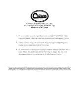
Inlet
Inlet
Inlet
Shaft
Cam ring
Outlet
Outlet
Outlet
Vane
Pump rotation
Rotor
Section II —
Description (cont.)
B. Assembly and Construction
Section III –
Principles of
Operation
A. Pumping Cartridge
VMQ Pumps can be used in
both industrial and mobile
applications. For pump ratings,
methods of installation or other
application information, refer to
the applicable sales installation
drawing or consult an
application engineer.
Basic Pumps. The pump
illustrated in Figure 1 is
representative of all single
pumps in this series. The pump
consists principally of an inlet
housing, outlet body, drive
shaft, and pumping cartridge.
The principal components of a
cartridge are an elliptical cam
ring, a slotted rotor splined to
the drive shaft, an inlet and
outlet support plate, two wafer
plates on either side of the
cam ring, and twelve vanes
and under vane pins fitted to
the rotor slots. Fluid enters the
cartridge through the inlet port
in the cover and is discharged
through the outlet wafer plate
and support plate to the outlet
port in the body.
C. Application
As mentioned in Section II,
fluid flow is developed in the
pumping cartridge. The action
of the cartridge is illustrated in
Figure 3. The rotor is driven
within the ring by the
driveshaft, which is coupled to
a power source. As the rotor
turns, centrifugal force on the
vanes, aided by under-vane
pressure fed from the outlet
port, causes the vanes to
follow the elliptical inner
surface of the ring.
Radial movement of the vanes
and turning of the rotor causes
the chamber volume between
the vanes to increase as the
vanes pass the inlet sections
of the ring. This results in a
low pressure condition which
allows atmospheric pressure
to force fluid into the
chambers.
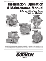
An additional inlet fluid path
exists through a drilled hole in
the cam ring. This hole
connects the inlet port directly
to the inlet areas of the cam
ring and provides an additional
flow path for fluid to get into
the cartridge. See Figure 2.
Fluid is trapped between the
vanes and carried past a
sealing land to the outlet
section of the ring. As the
outlet section is approached,
the chamber volume
decreases and fluid is forced
out into the system. System
pressure is fed under the
vanes via the under vane pins,
assuring their sealing contact
against the ring during normal
operation.
The pin-vane design provides a
means of controlling outward
thrust of the vane against the
ring and maintains tip loads
within reasonable limits. In the
pin-vane cartridge, full system
pressure is continuously
applied only to the cross
sectional area of the pin. This
area is small and thrust is
correspondingly light. This
selective application of
pressure assures that the
vanes will always be in contact
with the cam ring. A detailed
drawing of the VMQ rotating
group can be seen in Figure 4.
B. Vane Pressure Feed
8 EATON Vickers Single, Double, Triple and Thru-drive Pumps Overhaul Service Manual V-PUVN-TS001-E October 2002
Figure 3
Figure 2

EATON Vickers Single, Double, Triple and Thru-drive Pumps Overhaul Service Manual V-PUVN-TS001-E October 2002 9
Section III —
Principles of
Operation (cont.)
C. Hydraulic Balance
The main function of the
wafer plates is to control the
pressure timing of the pump.
Machined cavities in the wafer
plates distribute high pressure
from the outlet ports to the
terminal holes in the rotor.
These cavities also feed high
pressure through the rotor to
the pins behind the vanes.
With high pressure distributed
through the rotor and applied
to the under vane pins, the
forces between the vane tip
and cam are regulated. Finally,
metering grooves in the plates
are positioned in such a way to
reduce excess cavitation, thus
limiting the overall sound level
of the pump. The position of
the wafer plates in the
cartridge kit can be seen in
Figure 5.
VMQ wafer plates have a
bronze finish that rides next to
the rotor and provides excellent
wear and thermal shock
characteristics.
The inlet and outlet support
plates hold the wafer plates in
position and contain passages
which allow fluid to pass from
the inlet port to the pumping
cartridge and from the
cartridge to the outlet port.
The pump ring is shaped so
the two pumping chambers are
formed 180 degrees apart
(Figure 3). Thus, opposing
hydraulic forces which
develop side loads on the
shaft cancel out.
D. Wafer Plate Operation
Figure 5. Wafer Plate Operation
Inlet Window
Vane Cross Section
Pressure Balance Holes in Vane
Under Vane Pin
Rotor Terminal Hole
Rotor Bushing
Wafer Plate
Outlet Window
Rotor
Figure 4. VMQ Wafer Plate, Rotor and Vanes
Wafer Plates
Under Vane Pin
Internal Rotor Cavity
Rotor Terminal Hole
Outlet Port
Inlet Port

10 EATON Vickers Single, Double, Triple and Thru-drive Pumps Overhaul Service Manual V-PUVN-TS001-E October 2002
Section III —
Principles of
Operation (cont.)
E. Outlet Bodies
Two outlet body configurations
and two shaft seal arrange-
ments are available for the
series 30 VMQ pumps. See
Figures 6a and 6b.
Double shaft seal models
utilize a drain hole opening
between the two seals. This
drain hole is used to prevent
cross contamination between
the gearbox and the pump.
If one seal were to fail, the
fluid would drain through the
hole and not past the opposing
seal. Series 30 VMQ pumps
use shaft seals that are rated at
20 PSIG (1.38 bar). Higher
pressure shaft seals are
available. See your Eaton sales
representative for further
details.
Section IV –
Installation and
Operating Instructions
A. Installation Drawings
See the series 30 VMQ
product catalog for installation
dimensions.
B. Mounting and Drive Connections
Eaton high performance vane
pumps are designed for foot or
flange mounting.
1. Direct Drive. A pilot on the
pump mounting flange (Figure
7) assures correct mounting
and shaft alignment, provided
the pilot is firmly seated in the
accessory pad of the power
source. Care should be
exercised in tightening all
flange mounting screws to
prevent misalignment.
If gaskets are used between
flanges, they should be
installed carefully so as to lie
flat and should not be the type
that will take a set. Shaft keys
and couplings must be properly
seated to avoid slipping and
possible shearing.
Proper coupling alignment is
essential to prolong pump life.
Primary Seal
Primary Seal
Secondary Seal
Figure 6a. Single Shaft Seal Models Figure 6b. Double Shaft Seal Models
Drain Hole

EATON Vickers Single, Double, Triple and Thru-drive Pumps Overhaul Service Manual V-PUVN-TS001-E October 2002 11
Section IV —
Installation and Operating
Instructions (cont.)
C. Shaft Rotation
General Data
Oil in a hydraulic system
performs the dual function of
lubrication and transmission of
power. It constitutes a vital
factor in a hydraulic system and
careful selection of it should be
made with the assistance of a
reputable supplier. Proper
selection of oil assures
satisfactory life and operation
of system components with
particular emphasis on
hydraulic pumps. Any oil
selected for use with pumps is
acceptable for use with valves
or motors.
See the Series 30 VMQ
product catalog for hydraulic
fluid guidelines.
Where special considerations
indicate a need to depart from
the recommended oils or
operating conditions, see your
Eaton representative.
Cleanliness
Clean fluid is the best
insurance for long service life.
Eaton recommends a fluid
cleanliness of ISO 18/16/13 or
better. To insure your hydraulic
system is clean, perform the
following steps.
1. Clean (flush) entire new
system to remove paint, metal
chips, welding shot, etc.
2. Filter each change of oil to
prevent introduction of
contaminants into the system.
3. Provide continuous oil
filtration to remove sludge and
products of wear and corrosion
generated during the life of the
system.
4. Provide continuous
protection of system from
entry of airborne
contamination, by sealing the
system and/or by proper
filtration of the air.
5. Proper oil filling and
servicing of filters, breathers,
reservoirs, etc., cannot be
overemphasized.
6. Good system and reservoir
design will insure that aeration
of the oil is kept to a minimum.
CAUTION
Pump shafts are
designed to be
installed in
couplings with a slip fit or very
light press. Pounding the
coupling on the shaft can ruin
the bearings. Shaft tolerances
are shown on the pump
installation drawings.
2. Indirect Drive. Indirect drive
is not recommended for these
pumps.
Figure 7. Pilot Diameter
Pilot Diameter
Shaft
NOTE
Pumps are normally
assembled for right hand
(clockwise) rotation as viewed
from the shaft end. A pump
made for left hand rotation is
identified by an “L” in the
model code. (See Table 1)
NOTE
If it is desired to reverse the
direction of drive rotation, it is
necessary to disassemble the
pump and reverse the location
of the cartridge cam ring and
wafer plates. (See Section VI,
Part C)
CAUTION
Never drive a
pump in the wrong
direction of
rotation. Seizure may result,
necessitating extensive
repairs.
D. Piping and Tubing
1. All pipes and tubing must be
thoroughly cleaned before
installation. Recommended
methods of cleaning are
sandblasting and wirebrushing.
2. To minimize flow resistance
and the possibility of leakage,
use only as many fittings and
connections as necessary for
proper installation.
3. The number of bends in
tubing should be kept to a
minimum to prevent excessive
turbulence and friction of oil
flow. Tubing must not be bent
too sharply. The recommended
radius for bends is three times
the inside diameter of the
tube.
E. Hydraulic Fluid Recommendations

12 EATON Vickers Single, Double, Triple and Thru-drive Pumps Overhaul Service Manual V-PUVN-TS001-E October 2002
Section IV —
Installation and Operating
Instructions (cont.)
F. Overload Protection
Self priming: With a minimum
drive speed of 600 RPM, a
pump should prime
immediately. Failure to prime
within a short length of time
may result in damage due to
lack of lubrication. Inlet lines
must be tight and free from air
leaks. However, it may be
necessary to loosen a fitting on
the outlet side of the pump to
purge entrapped air.
No load starting: These
pumps are designed to start up
with no load on the pressure
ports. They should never be
started against a load or a
closed center valve.
E. Hydraulic Fluid Recommendations (cont.)
Sound Level
Noise is indirectly affected by
the fluid selection, but the
condition of the fluid is of
paramount importance in
obtaining optimum reduction
of system sound levels.
Some of the major factors
affecting fluid conditions that
cause the loudest noises in a
hydraulic system are:
1. Very high viscosities at start-
up temperatures can cause
pump noises due to cavitation.
2. Running with a moderately
high viscosity fluid will slow
the release of entrained air. The
fluid will not be completely
purged of such air in the time it
remains in the reservoir and air
will be recycled through the
system.
3. Aerated fluid can also be
caused by ingestion of air
through the pipe joints of inlet
lines, high velocity discharge
lines, cylinder rod packings, or
by fluid discharging above the
fluid level in the reservoir. Air in
the fluid causes a noise similar
to cavitation.
4. Contaminated fluids can
cause excessive wear of
internal pump parts, which
may result in increased
sound levels.
Relief valves must be installed
in the system as close to the
pump outlets as possible. The
relief valve limits pressure in
each system to a prescribed
maximum and protects
components from excessive
pressure. Each relief valve
pressure setting depends on
the work requirements of the
circuit being fed.
G. Port Positions
H. Start-Up
The pump cover can be
assembled in four positions
with respect to the body.
A letter in the model code
identifies the orientation of the
inlet and outlet ports. The cover
position of a VMQ single pump
is shown in Figure 8 as an
example.
Inlet Cover Positions
Model
(Viewed from cover end)
VMQ1* *A* * 030 Opposite Outlet Port
VMQ1* *B* * 030 90°Clockwise from Outlet
VMQ1* *C* * 030 Inline with Outlet
VMQ1* *D* * 030 90° Counterclockwise from Outlet
Figure 8. Cover Positions
Disassembly and assembly procedures are in Section VI-B and E.
Whenever it is possible to do
so, fill the pump ports with
system hydraulic fluid. This
will make it easier for the
pump to prime when it is first
started.
Body (Outlet)
Cover (Inlet)
A
B
C
D

EATON Vickers Single, Double, Triple and Thru-drive Pumps Overhaul Service Manual V-PUVN-TS001-E October 2002 13
Section V —
Inspection and
Maintenance
A. Inspection
B. Adding Fluid to the System
Table 4 lists the common
difficulties experienced with
vane pumps and hydraulic
systems. It also indicates the
probable causes and remedies
for each of the troubles listed.
It should always be
remembered that many
apparent pump failures are
actually due to the failure of
other parts of the system. The
cause of improper operation is
best diagnosed with adequate
testing equipment and a
thorough under-standing of the
complete hydraulic system.
Periodic inspection of the fluid
condition and tube or piping
connections reduce time
consuming breakdowns
and unnecessary parts
replacement. The following
should be checked regularly.
1. All hydraulic connections
must be kept tight. A loose
connection in a pressure line
will permit the fluid to leak
out. If the fluid level becomes
so low as to uncover the inlet
pipe opening in the reservoir,
extensive damage to the
pump can result. In suction or
return lines, loose connections
permit air to be drawn into the
system, resulting in noisy
and/or erratic operation.
2. Clean fluid is the best
insurance for long service life.
Therefore, the reservoir should
be checked periodically for dirt
or other contaminates. If the
fluid becomes contaminated,
the system should be
thoroughly drained and the
reservoir cleaned before new
fluid is added.
3. Filter elements also should
be checked and replaced
periodically. A clogged filter
element results in a higher
pressure drop. This can force
particles through the filter
which would ordinarily be
trapped, or can cause the
bypass to open, resulting in
a partial or complete loss of
filtration.
4. Air bubbles in the reservoir
can ruin the pump and other
components. If bubbles are
seen, locate the source of the
air and seal the leak. (See
Table 3)
5. A pump which is running
excessively hot or noisy is a
potential failure. Should a
pump become noisy or over-
heated, the machine should be
shut down immediately and
the cause of improper
operation corrected.
When hydraulic fluid is added
to replenish the system, it
should always be poured
through a fine wire screen
(200 mesh or finer) or
preferably pumped through
a 10 micron (absolute) filter.
It is important that the fluid be
clean and free of any
substance which could cause
improper operation or wear of
the pump or other hydraulic
units. Therefore, the use of
cloth to strain the fluid should
be avoided to prevent lint from
getting into the system.
C. Adjustments
No periodic adjustments are
required, other than to
maintain proper shaft
alignment with the driving
medium.
D. Lubrication
Internal lubrication is provided
by the fluid in the system.
Lubrication of the shaft
coupling should be as specified
by their manufacturers.
E. Replacement Parts
Reliable operation throughout
the specified operating range
is assured only if genuine
Vickers parts are used.
Sophisticated design
processes and materials are
used in the manufacture of our
parts. Substitutions may result
in early failure.
F. Product Life
G. Troubleshooting
The longevity of these
products is dependent upon
environment, duty cycle,
operating parameters and
system cleanliness. Since
these parameters vary from
application to application, the
ultimate user must determine
and establish the periodic
maintenance required to
maximize life and detect
potential component failure.

14 EATON Vickers Single, Double, Triple and Thru-drive Pumps Overhaul Service Manual V-PUVN-TS001-E October 2002
Section V —
Inspection and
Maintenance
(cont.)
TROUBLE PROBABLE CAUSE REMEDY
Pump not delivering fluid. Driven in the wrong direction of rotation. The drive direction must be changed immediately to
prevent seizure. Refer to Section VI.C. for the correct
ring position for each direction of rotation.
Coupling or shaft sheared or disengaged. Disassemble the pump and check the shaft and
cartridge for damage. (See Section VI) Replace the
necessary parts.
Fluid intake pipe in reservoir restricted. Check all strainers and filters for dirt and sludge.
Clean if necessary.
Fluid viscosity too heavy to pick up prime. Completely drain the system. Add new filtered fluid of
the proper viscosity.
Air leaks at the intake. Pump not Check the inlet connections to determine where air is
priming. being drawn in.Tighten any loose connections. See that
the fluid in the reservoir is above the intake pipe
opening. Check the minimum drive speed which may
be too slow to prime the pump.
Vane(s) stuck in the rotor slots(s). Disassemble the pump. Check for dirt or metal chips.
Clean the parts thoroughly and replace any damaged
pieces. If necessary, flush the system and refill it with
clean fluid.
Insufficient pressure build-up. System relief valve set too low. Use a pressure gage to correctly adjust the valve.
Pump making noise. Pump intake partially blocked. Service the intake strainers. Check the fluid condition
and, if necessary, drain and flush the system. Refill
with clean fluid.
Air leaks at the intake or shaft seal. Check the inlet connections and seal to determine
(Oil in reservoir would probably be foamy.) where air is being drawn in.tighten any loose
connections and replace the seal if necessary. See
that the fluid in the reservoir is above the intake pipe
opening.
Pump drive speed too slow or too fast. Operate the pump at the recommended speed.
Coupling misalignment. Check if the shaft seal bearing or other parts have
been damaged. Replace any damaged parts. Realign
the coupled shafts.
Table 4. Troubleshooting Chart

EATON Vickers Single, Double, Triple and Thru-drive Pumps Overhaul Service Manual V-PUVN-TS001-E October 2002 15
Section V —
Inspection and
Maintenance
(cont.)
Bearing
O-Ring
Retaining Ring
Back Up Ring
O-Ring
Outlet Body
Cover/Body O-Ring
Secondary Seal
Key
Primary Seal
Shafts
Outlet Support Plate
Inlet Cover
Assembly Pin
Kit Seals
Housing Bolt
Inlet Wafer Plate
Inlet Support Plate
Cartridge Torque Pin
Vane and Under Vane Pin
Rotor
Retaining Ring
Back Up Ring
Anti Rotation Torque Pin
Cam Ring
Outlet Wafer Plate
Figure 9a. Exploded View of VMQ Single Pump
Table 5 - Single Pump Housing Torque Specs
ISO (NM) SAE (ft
•lb)
Dry Oiled Dry Oiled
VMQ125 153 ± 16 115 ± 12 113 ± 11 85 ± 9
VMQ135 305 ± 31 229 ± 23 225 ± 23 169 ± 17
VMQ145 305 ± 31 229 ± 23 225 ± 23 169 ± 17

16 EATON Vickers Single, Double, Triple and Thru-drive Pumps Overhaul Service Manual V-PUVN-TS001-E October 2002
Section V —
Inspection and
Maintenance
(cont.)
O-Rings Inlet Housing
Thru-Drive Coupling
Thru-Drive Adapter
Thru-Drive Shafts
Table 6 - Thru-Drive Pump Housing Torque Specs
INLET HOUSING THRU-DRIVE ADAPTOR (SAE A & SAE B) THRU-DRIVE ADAPTOR (SAE C)
ISO (NM) SAE (ft•lb) ISO (NM) SAE (ft•lb) ISO (NM) SAE (ft•lb)
Dry Oiled Dry Oiled Dry Oiled Dry Oiled Dry Oiled Dry Oiled
VMQ125T 153+/-16 115+/-12 113+/-11 85+/-9 — ——— ———
VMQ135T 305+/-31 229+/-23 225+/-23 169+/-17 153+/-16 115+/-12 113+/-11 85+/-9 305+/-31 229+/-23 225+/-23 169+/-17
VMQ145T 305+/-31 229+/-23 225+/-23 169+/-17 153+/-16 115+/-12 113+/-11 85+/-9 305+/-31 229+/-23 225+/-23 169+/-17
Figure 8b. Exploded View of VMQ Thru-Drive Pump

EATON Vickers Single, Double, Triple and Thru-drive Pumps Overhaul Service Manual V-PUVN-TS001-E October 2002 17
Section V —
Inspection and
Maintenance
(cont.)
Table 7 - Double and Triple Pump Housing Torque Specs
INLET HOUSING OUTLET COVER OUTLET SECTION
ISO (NM) SAE (ft•lb) ISO (NM) SAE (ft•lb) ISO (NM) SAE (ft•lb)
Dry Oiled Dry Oiled Dry Oiled Dry Oiled Dry Oiled Dry Oiled
VMQ22525 153+/-16 115+/-12 113+/-11 85+/-9 — ——— ————
VMQ23525 305+/-31 229+/-23 225+/-23 169+/-17 153+/-16 115+/-12 113+/-11 85+/-9 ————
VMQ24525 305+/-31 229+/-23 225+/-23 169+/-17 153+/-16 115+/-12 113+/-11 85+/-9 ————
VMQ24535 305+/-31 229+/-23 225+/-23 169+/-17 305+/-3 229+/-23 225+/-23 169+/-17 ————
VMQ3352525 305+/-31 229+/-23 225+/-23 169+/-17 153+/-16 115+/-12 113+/-11 85+/-9 305+/-31 229+/-23 225+/-23 169+/-17
VMQ3453525 305+/-31 229+/-23 225+/-23 169+/-17 153+/-16 115+/-12 113+/-11 85+/-9 305+/-31 229+/-23 225+/-23 169+/-17
Figure 9c. Exploded View of VMQ Double Pump
Outlet Cover
Inlet Housing

18 EATON Vickers Single, Double, Triple and Thru-drive Pumps Overhaul Service Manual V-PUVN-TS001-E October 2002
Section V —
Inspection and
Maintenance
(cont.)
Figure 9d. Exploded View of VMQ Triple Pump
Outlet Section
Table 7 - Double and Triple Pump Housing Torque Specs
INLET HOUSING OUTLET COVER OUTLET SECTION
ISO (NM) SAE (ft•lb) ISO (NM) SAE (ft•lb) ISO (NM) SAE (ft•lb)
Dry Oiled Dry Oiled Dry Oiled Dry Oiled Dry Oiled Dry Oiled
VMQ22525 153+/-16 115+/-12 113+/-11 85+/-9 — ——— ————
VMQ23525 305+/-31 229+/-23 225+/-23 169+/-17 153+/-16 115+/-12 113+/-11 85+/-9 ————
VMQ24525 305+/-31 229+/-23 225+/-23 169+/-17 153+/-16 115+/-12 113+/-11 85+/-9 ————
VMQ24535 305+/-31 229+/-23 225+/-23 169+/-17 305+/-3 229+/-23 225+/-23 169+/-17 ————
VMQ3352525 305+/-31 229+/-23 225+/-23 169+/-17 153+/-16 115+/-12 113+/-11 85+/-9 305+/-31 229+/-23 225+/-23 169+/-17
VMQ3453525 305+/-31 229+/-23 225+/-23 169+/-17 153+/-16 115+/-12 113+/-11 85+/-9 305+/-31 229+/-23 225+/-23 169+/-17

EATON Vickers Single, Double, Triple and Thru-drive Pumps Overhaul Service Manual V-PUVN-TS001-E October 2002 19
Section VI —
Overhaul
B. Disassembly
WARNING
Before breaking a
circuit connection,
make certain that
power is off and system
pressure has been released.
Lower all vertical cylinders,
discharge accumulators and
block any load whose movement
could generate pressure. Plug all
removed units and cap all lines
to prevent the entry of dirt into
the system.
During disassembly, pay
particular attention to
identification of the parts,
especially the cartridges, for
correct assembly. Figure 9 is an
exploded view which shows the
proper relationship of parts for
disassembly and assembly.
Refer to Figure 9 for the correct
assembled relationship of the
parts. Various steps in the
overhaul process are shown in
Figures 10 through 17.
A. General
Basic Pump. Remove the foot
mounting and shaft key if used.
Support the pump on blocks or
clamp the body in a vise as
shown in Figure 10. If a vise is
used, use protective jaws to
avoid damage to the body and
its machined surfaces. Mark
the pump body and cover for
correct reassembly. Remove
the necessary screws to
disassemble the housing.
Remove all Housing O-Rings.
Pull and/or pry out the
cartridge(s) as shown in
Figure 11.
Remove the large spirolox ring
and pull the shaft and bearing
from the body. Drive the shaft
seals out of the body. If it is
necessary to remove the shaft
bearing, first remove the small
snap ring and then press the
shaft out of the bearing while
supporting the bearing inner
race.
The rotation of Eaton cartridge
kits can easily be changed from
clockwise to counterclockwise,
or vice versa, by following the
steps outlined below:
NOTE: A double or triple VMQ
pump will contain cartridge kits
that mirror one another. The
rotation direction of each
kit is specific to the pump
configuration. See Table 8
for application details.
Figure 10. Beginning disassembly
Figure 11. Cartridge removal
Figure 12
NOTE
Complete cartridges are
available in service kits
for rebuilding these pumps.
Refer to the Series 30 VMQ
Parts catalog for part
numbers.
Cover Screw
Index marks
for assembly
reference
If vice is used,
clamp here.
C. Drive Reversal

See figures 12 - 20 for a
pictorial explanation.
1.
Once the cartridge kit
has been removed from the
housing, place the kit on a clean
flat bench, outlet support plate
down. (Figure 12)
2. Remove the two socket head
cap screws holding the kit
together. Note the location of
the two screws in the inlet plate.
When the kit is reassembled in
the opposite direction, these
screws will be installed in the
opposite set of inlet plate holes.
(Figure 13)
3. Slide the inlet support plate
off of the inlet wafer plate.
(Figure 14)
4. Remove the inlet wafer plate,
cam ring, rotor, vanes, and
outlet wafer plate as one unit
from the outlet support plate.
(Figure 15)
5. Rotate this group of
components 180 degrees
and place it back on the outlet
support plate. The etched arrow
in the ring should be pointing
the opposite direction as before.
Do not attempt to remove the
vanes. They should be contained
between the wafer plates as the
180° rotation is performed.
(Figure 16)
6. Align the inlet windows
of the wafer plates to the inlet
windows of the outlet support
plate.Place the inlet support
plate back on the rotating group,
aligning its inlet windows with
the rest of the kit. Reinstall and
finger tighten the socket head
cap screws in the opposite set
of holes as before. In order for
the kit to fit back in the housing,
it must first be aligned. This can
be done by placing the kit on its
side and rolling it on a hard, flat,
clean bench. While the kit is on
its side, tighten the SCHS snug.
Finally, place the kit upright and
tighten the screws to the torque
specs below (Figures 17-20):
25 VMQ 20 in.lb. (2.28 Nm)
35 VMQ 20 in.lb. (2.28 Nm)
45 VMQ 40 in.lb. (4.55 Nm)
All parts must be thoroughly
clean and kept clean during
inspection and assembly.
1. Remove the shaft seal(s),
O-rings, back-up rings and seal
pack subassemblies. Use a new
seal kit for reassembly. Refer to
the VMQ parts catalog for kit
numbers.
2. If the pump has
demonstrated poor performance
or loud noise, the cartridge
kit must be replaced. These
problems were a result of a poor
system condition. Check inlet
conditions, fluid cleanliness, and
other system components that
may be faulty before installation
of a new cartridge kit.
NOTE:
Pre-assembled replacement
cartridge kits are available.
If the old cartridge is worn
extensively, a new kit should
be used.
3. Rotate the bearing while
applying pressure to check for
wear, looseness and pitted or
cracked races.
4. Inspect seal and bushing
mating surfaces on shaft for
scoring or wear. Replace
the shaft if marks cannot be
removed by light polishing.
20 EATON Vickers Single, Double, Triple and Thru-drive Pumps Overhaul Service Manual V-PUVN-TS001-E October 2002
Section VI —
Overhaul (cont.)
Figure 13
Figure 14
Figure 15
Figure 16
C. Drive Reversal (cont.)
D. Inspection and Repair
TABLE 8. CARTRIDGE KIT BUSHING LOCATIONS AND KIT ROTATION SETUP
(location of bushing in cartridge kit, assuming a right hand rotation shaft)
R = right hand rotation kit L = left hand rotation kit
Pump Shaft End Kit Center Kit Cover End Kit
25, 35, 45 Single Inlet Plate (R) ——
& Thru-Drive (R)
2525 Double (R) No Bushing (R) — Outlet plate (L)
3525 Double (R) Inlet Plate (R) — No Bushing (L)
4525 Double (R) Inlet Plate (R) — No Bushing (L)
4535 Double (R) Inlet Plate (R) — No Bushing (L)
352525 Triple (R) Inlet Plate (R) No Bushing (L) Outlet Plate (L)
453525 Triple (R) Inlet Plate (R) Outlet Plate (L) No Bushing (L)
*Note: The opposite rotating kits would be used in a (L) pump.
/