
FlexWave
®
Prism Remote Unit and RF Module
Installation Guide • FWPP-504-02 • May 2017
FWD NOT TO
EXCEED +6 dBm
FAN
SeRF II
NETWORK
CRAFT
DC POWER
CDIU
CDIU
CDIU
CPRI PORT 1
CPRI PORT 2
CPRI PORT 1
CPRI PORT 2
CPRI PORT 1
CPRI PORT 2
CRAFT
CRAFT
CRAFT
REF
OUT
REF
OUT
REF
OUT
PATH A
PATH B
CONFIG
PWR
PATH A
PATH B
CONFIG
PWR
PATH A
PATH B
CONFIG
PWR
REV
RF OUT
REV
RF OUT
PWR
STATUS
PWR
STATUS
FWD
REF IN
NOKIA NOKIA
NOKIA
FWD NOT TO
EXCEED +6 dBm
FWD
REF IN

DISCLAIMER
ThisdocumenthasbeendevelopedbyCommScope,andisintendedfortheuseofitscustomersandcustomersupportpersonnel.
Theinformationinthisdocumentissubjecttochangewithoutnotice.Whileeveryefforthasbeenmadetoeliminateerrors,
CommScopedisclaimsliabilityforanydifficultiesarisingfromtheinterpretationoftheinformationcontainedherein.The
informationcontainedhereindoesnotclaimtocoveralldetailsorvariationsinequipment,nortoprovideforeverypossible
incidenttobemetinconnectionwithinstallation,operation,ormaintenance.Thisdocumentdescribestheperformanceofthe
productunderthedefinedoperationalconditionsanddoesnotcovertheperformanceunderadverseordisturbedconditions.
Shouldfurtherinformationbedesired,orshouldparticularproblemsarisewhicharenotcoveredsufficientlyforthepurchaser's
purposes,contactCommScope.
CommScopereservestherighttochangeallhardwareandsoftwarecharacteristicswithoutnotice.
COPYRIGHT
©2017CommScope,Inc.AllRightsReserved.Alltrademarksidentifiedby®or™areregisteredtrademarksortrademarks,
respectively,ofCommScope,Inc.
Thisdocumentisprotectedbycopyright.Nopartofthisdocumentmaybereproduced,storedinaretrievalsystem,or
transmitted,inanyformorbyanymeans,electronic,mechanicalphotocopying,recording,orotherwisewithouttheprior
writtenpermissionofCommScope.
OTHER TRADEMARKS
Namesofotherproductsmentionedhereinareusedforidentificationpurposesonlyandmaybetrademarksand/orregistered
trademarksoftheirrespectivecompanies.

FWPP-504-02 FlexWave
®
Prism Remote Unit and RF Module Installation Guide
© May 2017 CommScope, Inc. Page iii
TABLE OF CONTENTS
Document Overview...............................................................................................................................................................................................1
Document Revision History........................................................................................................................................................................................3
Document Cautions and Notes ..................................................................................................................................................................................3
Abbreviations Used in this Guide ...............................................................................................................................................................................4
Overview of Prism Remote Units............................................................................................................................................................................5
Prism Remote Unit Components................................................................................................................................................................................6
Ports and Connectors .................................................................................................................................................................................................7
Bottom of an AC-Powered Quad-Bay PRU .........................................................................................................................................................8
DC-Powered Quad-Bay PRU ...............................................................................................................................................................................9
Remote Unit Status LED ...................................................................................................................................................................................10
SeRF Module LEDs ............................................................................................................................................................................................11
Overview of RF Modules for Prism Remote Units .................................................................................................................................................12
RF Module Digital/Analog Radio Transceivers .........................................................................................................................................................12
RF Module Types ......................................................................................................................................................................................................14
Single- and Dual-Bay RF Modules with Classic or SuperDARTs ........................................................................................................................15
HDM RF Modules..............................................................................................................................................................................................16
Legacy Dual-Bay 40W RF Modules ...................................................................................................................................................................17
RF Module Components...........................................................................................................................................................................................18
Linear Power Amplifiers ...................................................................................................................................................................................19
Duplexer and Low Noise Amplifier ...................................................................................................................................................................20
Digital Processing Module................................................................................................................................................................................20
Cables ...............................................................................................................................................................................................................20
LEDS on Narrowband HDM RF Modules ..........................................................................................................................................................21
LEDS on Wideband and Fullband HDM RF Modules ........................................................................................................................................22
Configuring the System with RF............................................................................................................................................................................23
RF Group Assignments for PRU RF Module Bays......................................................................................................................................................23
Understanding RF Cable Rules .................................................................................................................................................................................26
RF Module Cables and Supported Bay Use for Single-Card, Dual-Card,
and HDM RF Modules...............................................................................................................................................................................26
RF Module Cables and Supported Bay Installations for Legacy Dual-Bay
40W RF Modules ......................................................................................................................................................................................27
Install the Prism Remote Unit...............................................................................................................................................................................29
Planning for a Prism Remote Unit Installation .........................................................................................................................................................29
Safety Precautions............................................................................................................................................................................................29
Mounting Plans ................................................................................................................................................................................................30
Installation Tools and Supplies.........................................................................................................................................................................36
Tools Required for All Mounting Methods...............................................................................................................................................36
Additional Tools and Supplies Required for Steel-Pole Mounting ...........................................................................................................36
Additional Tools and Supplies Required for Wood-Pole Mounting..........................................................................................................37
Additional Tools and Supplies Required for Flat-Surface Mounting ........................................................................................................37
Tools and Supplies Required to Connect a PRU .......................................................................................................................................38
Unpack and Inspect the Prism Remote Unit and Components................................................................................................................................39
Mount the Prism Remote Unit .................................................................................................................................................................................42
Mounting Cautions...........................................................................................................................................................................................42
Mounting Methods ..........................................................................................................................................................................................42
Steel Pole Installation Using Steel Banding ..............................................................................................................................................43
Pole Mount Installation Using Bolts .........................................................................................................................................................46
Wood-Framed Wall Mounting Procedure................................................................................................................................................47
Masonry Wall Mounting...........................................................................................................................................................................49
Installing a PRU on the Mounting Bracket................................................................................................................................................51
Ground the PRU Chassis...........................................................................................................................................................................................52
Connect a Network Cable to the PRU Chassis ..........................................................................................................................................................54
Connect Fiber Cable to the PRU Chassis...................................................................................................................................................................56
Option A: Hardened Multi-Fiber Optic Connector ...........................................................................................................................................56
Option B: Fiber Pass-Through Connector.........................................................................................................................................................62
Option C: ProAx Connector (Legacy AC-Powered PRUs)..................................................................................................................................67
Connect the Antenna Cable .....................................................................................................................................................................................71
Determine the Circuit Breaker or Fuse for the PRU .................................................................................................................................................72
Power Consumption.........................................................................................................................................................................................73
Power Consumption Tables..............................................................................................................................................................................74

FlexWave
®
Prism Remote Unit and RF Module Installation Guide FWPP-504-02
Page iv © May 2017 CommScope, Inc.
Table of Contents
Connect the Power Wiring .......................................................................................................................................................................................76
Option 1: Connect the AC Power Wiring ..........................................................................................................................................................76
Option 2: Connect the DC Power Wiring..........................................................................................................................................................79
(Optional) Connect the Prism Remote Unit to a UPS ...............................................................................................................................................82
Install the RF Module(s) .......................................................................................................................................................................................84
Safety Precautions....................................................................................................................................................................................................84
Guard against Damage from Electro-Static Discharge .............................................................................................................................................85
Unpack and Inspect the RF Module .........................................................................................................................................................................85
Remove Release Liners from the RF Module ...........................................................................................................................................................86
Check the DC Power Switch for the Module Bay .....................................................................................................................................................88
Dual-Bay Modules Only—Remove the Module Bay Shelf........................................................................................................................................89
Install the RF Module into the Prism Remote Chassis..............................................................................................................................................90
Secure RF Module Latches .......................................................................................................................................................................................97
Connect Latches on Single-Bay and HDM RF Modules.....................................................................................................................................98
Connect Latches on Dual-Bay RF Modules .......................................................................................................................................................99
Latches on Legacy Dual-Bay 40W RF Modules...............................................................................................................................................100
Verify that the RF Module Mounting Hook is Engaged ..................................................................................................................................101
Connect the RF Module Cables to the PRU Chassis ...............................................................................................................................................101
Connecting Cables in a Single-Bay RF Module Installation.............................................................................................................................101
Connecting Cables in a Dual-Bay RF Module Installation...............................................................................................................................106
Power on the RF Module(s) and the Prism Remote Unit .......................................................................................................................................110
Close the Remote Unit Door and Solar Shield........................................................................................................................................................112
Provision the Prism Remote Unit ...........................................................................................................................................................................113
FlexWave Notch Filter (FWP-SPRINTFILTER)........................................................................................................................................................114
Fan Module Maintenance...................................................................................................................................................................................118
Annual Fan Checkup...............................................................................................................................................................................................118
Potential Fan Alarms ..............................................................................................................................................................................................118
Replacing the Fan Module......................................................................................................................................................................................118
Specifications .....................................................................................................................................................................................................121
Standards Certification.......................................................................................................................................................................................123
DCCS Global Technical Support...........................................................................................................................................................................124
Telephone Helplines...............................................................................................................................................................................................124
Online Support .......................................................................................................................................................................................................124
DCCS Technical Training .....................................................................................................................................................................................125
Accessing FlexWave User Documentation ..........................................................................................................................................................126
Accessing Prism User Documentation....................................................................................................................................................................126
Accessing Spectrum User Documentation .............................................................................................................................................................126

FWPP-504-02 FlexWave
®
Prism Remote Unit and RF Module Installation Guide
© May 2017 CommScope, Inc. Page 1
DOCUMENT OVERVIEW
ThisdocumentprovidestheinformationyouneedtoinstallaCommScopeFlexWave
®
PrismRemoteUnit(PRU).
InstallationinstructionsarealsoprovidedforthefollowingPrismRemoteUnitRFModulesthatresideinaPRU:
• Single-BayRFModules,whichincludestheHDMandTDDRFModules
• Dual-BayRFModules,whichincludestheDual-BandRFModulesandLegacy40WRFModules.
NOTE: RF Modules are ordered separately and must be installed in a Prism Remote Unit in the field.
Table1liststhePrismRemoteUnitchassisandTable2throughTable8onpage3listthePrismRFModulesthat
thisinstallationguidesupports.
Table 1. Supported FlexWave Prism Remote Unit Chassis
Catalog Number Description
FP1-XXXXXXXXXXXRU Single-Bay Prism Remote
FP2-XXXXXXXXXXXRU Dual-Bay Prism Remote
FP3-XXXXXXXXXXXRU Tri-Bay Prism Remote
FP4-XXXXXXXXXXXRU Quad-Bay Prism Remote
Table 2. Supported High-Density Module (HDM), Single Bay RF Modules
Catalog Number Description
FWP-L4MT000MOD 20W Dual 700 Lower ABC, MIMO
FWP-L4 MT U4 MM OD 20W Dual 700 Lower ABC / 700 Upper C Non-Diversity
FWP-U4MT000MOD 20W 700 Upper C, MIMO
FWP-44MT000MOD 20W Dual 800 MIMO, with two External Filters
FWP-441T841MOD 20W Dual 800 SMR/ 1900 PCS, with 800 External Filter
FWP-C4MT000MOD 20W Dual 850 Cell/1900 PCS, Non-Diversity
FWP-B4MT000MOD 20W 850 MIMO
FWP-B410000MOD 20W 850 Wideband Cell, Non-Diversity
FWP-B810100MOD 40W 850 Wideband Cell, Non-Diversity
FWP-84MT000MOD 20W 1900 PCS MIMO, Non-Diversity
FWP-84MT A4M M OD 20W Dual 1900 PCS/2100
FWP-Z4MT000MOD 20W 2100 AWS-3 MIMO
FWP-W4MT000MOD 20W 2300 WCS, MIMO
FWP-T4MT000MOD-L 20W 2500 TDD Low, MIMO, 2496.5-2571.5 MHz
FWP-T4ST000MOD-H 20W 2500 TDD High, SISO, 2615-2690 MHz
FWP-A4 MT 00 0M O D 20W 2100 AWS MIMO, Non-Diversity
FWP-A416000MOD 20W 2100 AWS, Non-Diversity
FWP-A81T000MOD 40W 2100 AWS SISO, Non-Diversity
FWP-8416000MOD 20W 1900 PCS SISO, Non-Diversity
FWP-881T000MOD 40W 1900 PCS SISO, Non-Diversity

FlexWave
®
Prism Remote Unit and RF Module Installation Guide FWPP-504-02
Page 2 © May 2017 CommScope, Inc.
Document Overview
Table 3. Supported Classic DART, Single Bay RF Modules
Catalog Number Description
FWP-I210000MOD 6.5W 800 APAC, Non-Diversity, Classic (Extended 1 MHz)
FWP-4210000MOD 6.5W 800 SMR Module, Non-Diversity
FWP-J4 10D 0 0M OD 20W 850 Cell (870-890), Diversity Ready
FWP-8420000MOD 20W 1900 PCS Diversity
FWP-8410000MOD 20W 1900 PCS Non-Diversity
FWP-A420000MOD 20W 2100 AWS Diversity
FWP-A410000MOD 20W 2100 AWS Non-Diversity
FWP-B420000MOD 20W 850 Wideband Cell, Diversity
Table 4. Supported Classic DART, Two Bay RF Modules
Catalog Number Description
FWP-8810000MOD 40W 1900 PCS, Non-Diversity
FWP-A810000MOD 40W 2100 AWS, Non-Diversity
Table 5. Supported Single SuperDART, Non-Diversity, Single Bay RF Modules
Catalog Number Description
FWP-6216000MOD 10W 900 EGSM, Non-Diversity
FWP-K216000MOD 10W 900 P-GSM, Non-Diversity
FWP-F216000MOD 10W APAC EGSM, Non-Diversity
FWP-7416000MOD 20W 1800 GSM, Non-Diversity
FWP-9416D00MOD 20W 2100 UMTS Module, Diversity Ready
FWP-9416000MOD 20W 2100 UMTS, Non-Diversity
FWP-L416000MOD 20W 700 Lower ABC Module, Non-Diversity
FWP-U416000MOD 20W 700 LTE, UPPER C, SISO, Non-Diversity
FWP-U816100MOD 40W 700 Upper C, Non-Diversity
Table 6. Supported Dual SuperDART, Single Bay, Non-Diversity RF Modules
Catalog Number Description
FWP-741S000MOD 20W 1800 GSM
FWP-841S000MOD 20W 1900 PCS
FWP-A41S000MOD 20W 2100 AWS
FWP-941S000MOD 20W 2100 UMTS

Document Overview
FWPP-504-02 FlexWave
®
Prism Remote Unit and RF Module Installation Guide
© May 2017 CommScope, Inc. Page 3
Document Revision History
DOCUMENT CAUTIONS AND NOTES
Twotypesofmessages,identifiedbelow,appearinthetext:
CAUTION! Cautions indicate operations or steps that could cause personal injury, induce a safety problem in a
managed device, destroy or corrupt information, or interrupt or stop services.
NOTE: Notes contain information about special circumstances.
Table 7. Supported Single SuperDARTs, Diversity, Single Bay RF Modules
Catalog Number Description
FWP-6226000MOD 10W 900 EGSM
FWP-K226000MOD 10W 900 P-GSM
FWP-7426000MOD 20W 1800 GSM
FWP-9426000MOD 20W 2100 UMTS
FWP-A426000MOD 20W 2100 AWS
FWP-8426000MOD 20W 1900 PCS
Table 8. Supported Dual Classic DART, Two Bay RF Modules
Catalog Number Description
FWP-D210000MOD 6.5W 800/900 ESMR, Non-Diversity
Issue Document Date Technical Updates
FWPP-504-02 May 2017 Adds support for RF Module FWP-Z4MT000MOD (20W 2100 AWS-3 MIMO); see Table 2 on page 1.
FWPP-504-01 July 2016 The initial release of this installation guide (FWPP-504-01) was released when CommScope acquired TE
Connectivity’s telecom, enterprise and wireless business, which included the FlexWave Prism product line.
CommScope document FWPP-504-01 replaced TE document TECP-77-275. FWPP-504-01 also added support
for the HDM TDD RF Modules FWP-T4MT000MOD-L (20W 2500 TDD Low, MIMO, 2496.5-2571.5 MHz) and
FWP-T4ST000MOD-H (20W 2500 TDD High, SISO, 2615-2690 MHz), changed RF Module installation
instructions as PRUs no longer ship with any RF Modules factory installed, and added cautions to ensure that
the AC/DC Power switch to the Remote Unit chassis and the DC power switch to all RF Module bays are in their
OFF position before connecting or disconnecting coaxial cables.

FlexWave
®
Prism Remote Unit and RF Module Installation Guide FWPP-504-02
Page 4 © May 2017 CommScope, Inc.
Document Overview
ABBREVIATIONS USED IN THIS GUIDE
AC Alternating Current M Meter
AMP Amperes Mbps Megabits Per Second
AUX Auxiliary MDI Medium Dependent Interface
AWG American Wire Gauge MHz Megahertz
C Centigrade MIMO Multiple-Input Multiple-Output
CAT Category MM Millimeter
CDRH Center for Diseases and Radiological Health MOD Module
cm Centimeter MPE Maximum Permissible Exposure
DART Digital/Analog Radio Transceiver NC Normally Closed
dB Decibel NO Normally Open
dBm Decibel-milliwatts NOC Network Operations Center
DC Direct Current OSP Outside Plant
DCS Distributed Call Signaling PA Power Amplifier
DD Digital Dividend PA Power Amplifier
DIV Diversity PRIM Primary
DPA Dynamic Phase Alignment PRU Prism Remote Unit
DPM Digital Processing Module PWR Power
EMEA Europe, Middle east, Africa REV Reverse
EMC Electromagnetic Compatibility RF Radio Frequency
ESD Electro-Static Discharge Rx Receive
EU European Union SDART Super Digital/Analog Radio Transceiver
F Fahrenheit SeRF Serialized RF
FCC Federal Communications Commission SFP Small Form-Factor Pluggable
FDA Food and Drug Administration SYNTH Synthesizer
FRU Fullband Remote Unit TDD Time-Division Duplex
FWD Forward TIM Thermal-Interface Material
HDM High Density Module Tx Transmit
HMFOC Hardened Multi-Fiber Optic Connector UL Underwriters' Laboratories, Inc.
Hz Hertz UMTS Universal Mobile Telecommunications System
IC Industry Canada UPS Uninterrupted Power Supply
IP Internet Protocol VAC Volts, Alternating Current
LAN Local Area Network W Watt
LC Lead Covered WCS Wireless Communications Services
LED Light-Emitting Diode WDM Wavelength Division Multiplexer
LVDS Low-Voltage Differential Signaling

Overview of Prism Remote Units
FWPP-504-02 FlexWave
®
Prism Remote Unit and RF Module Installation Guide
© May 2017 CommScope, Inc. Page 5
OVERVIEW OF PRISM REMOTE UNITS
FlexWavePRUscontrolRFemissions,interfacewiththeFlexWavePrismHostUnitIIandperformtheopticalto
electricalconversionfortransporttotheantennas.ThePRUisanenvironmentally-sealedunitdesignedfor
outdoorusethathousestheelectronicassembliessuchastheDigital/AnalogRadioTransceiver(DART)board
andthePowerAmplifier,andsealsoutdirtandmoisture.ThePRUusesfanslocatedonthetopofeachunitto
coolitschassis.Theantennacableconnectors,fiberconnectors,ACorDCpowerconnector,andtheunitstatus
indicatorarelocatedonthebottomoftheunit.
APRUsupportsorprovidesthefollowingbasicfunctions:
• ReceivesontheforwardpaththedigitizedspectrumfromtheHostandconvertsthespectrumbackintoan
RFsignaltobedistributedviaanexternallymountedantennasystem.Onthereversepath,thePRUdigitizes
thedesignatedRFspectrumanddigitallytransportsitoversinglemodefiberorMillimeterWave(MMW)to
theHost.
• ProvidesRFinterface(antennaport)fortheantennas.
• AcceptseitherACorDCpowerinput.

FlexWave
®
Prism Remote Unit and RF Module Installation Guide FWPP-504-02
Page 6 © May 2017 CommScope, Inc.
Overview of Prism Remote Units
PRISM REMOTE UNIT COMPONENTS
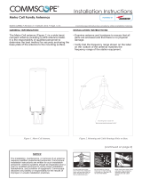
Figure1showsthemaincomponentsofthePRUanditscorrespondingRFModules.
Figure 1. Prism Remote Unit Components
SeRF Module
Main AC/DC Power
switch for the chassis
HDM RF Module
DC Power switches
for RF Modules
Fan Module
Cable connectors
RF Module slots

Overview of Prism Remote Units
FWPP-504-02 FlexWave
®
Prism Remote Unit and RF Module Installation Guide
© May 2017 CommScope, Inc. Page 7
PORTS AND CONNECTORS
MakesureyourefertothesectionthatdescribesthePRUdeployedinyourinstallation."Bottomofan
AC-PoweredQuad-BayPRU”onpage8and"DC-PoweredQuad-BayPRU”onpage9showsthedifferences
betweenanAC-poweredandaDC-poweredPRU.ThedifferenceswillbethesameforSingle-Bay,Dual-Bay,and
Tri-Baychassis.Additionally,forboththeAC-PoweredandDC-PoweredPRUs:
• ThenumberofAntennaconnectorsonthebottomofaPRUcorrespondstothenumberofRFModulebaysin
thatPRUmodel,wheretherearetwoAntennaconnectorsperbay.Forexample:
– TherearefourRFModulebaysinaQuad-BayPRU,sothereareeightAntennaconnectors.
– ThereisoneRFModulebayintheSingle-BayPRU,sotherearetwoAntennaconnectors.
• TheSingle-BayPRUonlyhasoneFiberconnectorwhereastheotherthreePRUmodelshavetwo.

FlexWave
®
Prism Remote Unit and RF Module Installation Guide FWPP-504-02
Page 8 © May 2017 CommScope, Inc.
Overview of Prism Remote Units
Bottom of an AC-Powered Quad-Bay PRU
Ref # Component Device Function
1 AUX connector Four contact closure inputs Connection points for two external alarm inputs.
2 Antenna
connectors
Eight Input/Output
Impedance 50Ω N-Type
connectors (female)
Connection points between the PRU and antennas that are labeled M
OD X TXO/RXO
or M
OD X TX1/RX1(where the first X can be A, B, C, or D). For further information,
see "Understanding RF Cable Rules” on page 26.
3 Fiber connectors One of the following:
• Hardened Multi-Fiber
Optic Connector (shown)
•Fiber Pass-Through
• ProAx connectors that
provide four BX5
connectors (Legacy PRUs)
Connection points between the PRU and the Outside Plant (OSP) box. The Single-BAY
PRU only has the Fiber 1 connector. For further information on the three Fiber
connector types, see "Connect Fiber Cable to the PRU Chassis” on page 56.
4 Dual-Ground
connector
Ground connector Grounds the PRU.
5 AC Power port Sealed 3-pin port Connection point between the PRU and an AC power junction box.
6Network
Connector port
RJ-45 female connector LAN Extension of the Host Unit Network that provides access to the Prism Network
for access and monitoring via an up to a 100 Mbps IP back-haul connection to remote
devices.
2
5
1
3
4
6

Overview of Prism Remote Units
FWPP-504-02 FlexWave
®
Prism Remote Unit and RF Module Installation Guide
© May 2017 CommScope, Inc. Page 9
DC-Powered Quad-Bay PRU
Ref # Component Device Function
1 DC Power port Pass-through gland Connection point between the PRU and a -40 to -60 Vdc power source.
2 Network Connector
port
RJ-45 female connector LAN Extension of the Host Unit Network that provides access to the Prism Network
for access and monitoring via an up to a 100 Mbps IP back-haul connection to
remote devices.
3 AUX connector Four contact closure inputs Connection points for two external alarm inputs.
4 Antenna connectors Eight Input/Output
Impedance 50Ω N-Type
connectors (female)
Connection points between the PRU and up to eight antennas that are labeled M
OD
X TXO/RXO or M
OD X TX1/RX1(where the first X can be A, B, C, or D). For further
information, see "Understanding RF Cable Rules” on page 26.
5 Fiber connectors One of the following:
• Hardened Multi-Fiber Optic
Connector (shown)
•Fiber Pass-Through
• ProAx connectors that
provide four BX5
connectors (Legacy PRUs)
Connection points between the PRU and the Outside Plant (OSP) box. For further
information on the three Fiber connector types, see "Connect Fiber Cable to the
PRU Chassis” on page 56.
6 Dual-Ground
connector
Ground connector Grounds the PRU.
POWER
48vdc/XXA
NETWORK
AUX
MOD A
TX1/RX1
MOD A
TXO/RXO
MOD B
TX1/RX1
MOD B
TXO/RXO
MOD C
TX1/RX1
MOD C
TXO/RXO
MOD D
TX1/RX1
MOD D
TXO/RXO
FIBER 1FIBER 2
123 4
5
6
CLASS 1
LASER PRODUCT

FlexWave
®
Prism Remote Unit and RF Module Installation Guide FWPP-504-02
Page 10 © May 2017 CommScope, Inc.
Overview of Prism Remote Units
Remote Unit Status LED
ThissectionillustratestheStatusLEDonaQuad-BayPRU.TheStatusLEDfortheSingle-Bay,Dual-Bay,and
Tri-BayPRUsisinthesamelocationandfunctionsthesameastheStatusLEDfortheQuad-BayPRU.
TheRemoteUnithasasingleredStatusLEDthatislocatedonthebottomofthechassis.Atsystemstartup,the
StatusLEDisredtoindicatethattheRemoteUnitispoweringupandthattheSeRFprocessordoesnotyetcontrol
theRemoteUnit;theStatusLEDwillremainredforapproximatelyoneminute.IfafterthreeminutestheStatus
LEDisstillred,itindicatestheRemoteUnitisunabletobootup.(SomecommonfailuresthatcanpreventthePRU
frombootingupincludeafaultyPowerSupply,SeRF,orCompactFlashCard.)
Boom of an AC-Powered PRU Boom of a DC-Powered PRU
Status LED
NETWORK
POWER
48VDC/XXA
MOD D
TX1/RX1
NETWORK
MOD D
TX1/RX1
POWER
100-240 VAC
50-60 Hz
XX AMPS
WARNING:
HIGH LEAKAGE CURRENT. EARTH
CONNECTION ESSENTIAL BEFORE
CONNECTING SUPPLY
MOD D
TX0/RX0
MOD D
TX0/RX0

Overview of Prism Remote Units
FWPP-504-02 FlexWave
®
Prism Remote Unit and RF Module Installation Guide
© May 2017 CommScope, Inc. Page 11
SeRF Module LEDs
NOTE: The SeRF Module LEDs automatically enter a LED Roll Test sequence (cycle through its colors) when the
SeRF FPGA is loaded (approximately 4 minutes after initial power up) or when a SeRF synthesizer failure
occurs. The LED Roll Test sequence takes approximately two seconds to complete, and cycles the
ALARM, SYNTH, and STATUS LEDs, after which the LEDs begin normal operation. Additionally, an active
SeRF Synthesizer failure causes the same LED sequencing approximately every minute until the SeRF
failure clears.
LED LED Color Description
POWER
•GREEN •Power OK and operating properly
• RED • Power supply out of tolerance
•OFF •No power present
STATUS
• GREEN
•RED
• No alarm for the SeRF II Module
• Initial bootup sequence and should become GREEN within 1 minute;
if RED after bootup, a Major alarm exists for the SeRF Module
SYNTH
•GREEN •Locked
• RED • Unlocked or is in initial bootup sequence
ALARM
•GREEN •No major alarm is present in the PRU or in any downstream unit
• RED • Initial bootup sequence, or a major alarm is present in the PRU or in any downstream unit
SeRF Module
POWER
STATUS
SYNTH
ALARM

FlexWave
®
Prism Remote Unit and RF Module Installation Guide FWPP-504-02
Page 12 © May 2017 CommScope, Inc.
Overview of RF Modules for Prism Remote Units
OVERVIEW OF RF MODULES FOR PRISM REMOTE UNITS
DependentonthePrismRemoteUnitmodel,aPRUenclosurecanhavefromonetofourRFModulebaysandcan
supportuptofourRFModules,asindicatedbythemodelname.Thatis,theSingle-BayPRUhasoneRFModule
bayandcanonlysupportoneRFModule,andtheQuad-BayPRUhasfourRFModulebaysandcansupportupto
fourRFModules.
ThefunctionoftheRemoteUnitRFModulesontheForwardPathisto:
• convertthedigitizedRFtransportedfromtheHosttoAnalogRF
• amplifytheAnalogRFsignal
• providesignalfiltering.
ThefunctionoftheRemoteUnitRFModulesontheReversePathisto:
• converttheAnalogRFfromthehandsettoDigitalRFfortransporttotheHost
• amplifytheDigitalRFsignal
• providesignalfiltering.
NOTE: The RF Modules are field replaceable, but cannot be serviced in the field.
RF MODULE DIGITAL/ANALOG RADIO TRANSCEIVERS
EachRFModulecansupportanyofthefollowingDigital/AnalogRadioTransceiver(DART)combinations:
• oneClassicDARToroneSingleSuperDART
• twoClassicDARTs(i.e.,the6.5W800/900ESMRModule,Non-Diversity,Classic)
• twoClassicDARTs—Diversity
• twoSingleSuperDARTs—Diversity
• oneDualSuperDART
• oneortwosetsofTxandRxBoards(HDM).
EachRFModulewillhaveuptotwo6-timeslotDARTsorone12-timeslotDARTperRFModule.
TheDARTtypedeterminesthemaximumnumberoflinks,wheretherecanbeuptoeightClassicDARTsorSingle
SuperDARTsthatsupport35MHzeach,orupto4DualSuperDARTsthatsupportupto75MHzeach.

Overview of RF Modules for Prism Remote Units
FWPP-504-02 FlexWave
®
Prism Remote Unit and RF Module Installation Guide
© May 2017 CommScope, Inc. Page 13
PrismsupportstheDARTModuletypeslistedbelow.
• ClassicDARTsare6-timeslotDARTsthatsupportupto35MHzcontiguousbandwidth(seeTable9).
• SingleSuperDARTsare6-timeslotDARTsthatsupporttwonon-contiguousbandsintheentirefrequency
rangeoftheDART,butcannotexceed35MHztotalRFbandwidth(seeTable10).
• DualSuperDARTsare12-timeslotDARTsthatsupportupto60-75MHz(seeTable11onpage14)
NOTE: Industry Canada PCS 20 dB nominal bandwidth is less than 61.5 MHz.
NOTE: Industry Canada AWS 20 dB nominal bandwidth is less than 47.2 MHz
Table 9. Single-Position Classic DARTs
DART Module Type Maximum
Bandwidth (MHz)
Maximum
Fiber Slots
800 APAC iDEN Classic 19 3
800 SMR Classic 7* 3
850 Cell Classic 25 4
900 SMR Classic 5 1
* Classic Prism RF Modules and Spectrum RAU support 18 MHz; Prism HDM 800 only
supports 7 MHz, per Sprint direction.
Table 10. Single-Position SuperDARTs*
DART Name Used in… Maximum
Frequency
Span (MHz)
Maximum
Bandwidth
(MHz)
Maximum
Fiber
Slots
Host Units HEUs
700 IABC SGL SuperDART Yes Yes 18 18 3
700 uC SGL SuperDART Yes Yes 10 10 2
900 EGSM SGL SuperDART Yes No 35 35 6
1800 GSM SGL SuperDART Yes No 75 35 6
1900 PCS SGL SuperDART Yes Yes 70 35 6
2100 AWS SGL SuperDART Yes Yes 45 35 6
20W 2100 AWS-3 MIMO Yes Yes 70 35 12
2100 UMTS SGL SuperDART Yes No 60 35 6
2300 WCS, MIMO Yes No 10 10 2
2500 TDD Low, MIMO Yes No 75 35 6
2500 TDD High, SISO Yes No 75 75 12
* When using a Host Unit with both a SeRF II and System Board II or III, the bandwidths and fiber for the following Single SuperDARTs can
be greater than 6 fiber slots, for full-band capability, when used in Host Unit Slots 1 and 3: 1800 GSM SGL SuperDART; 1900 PCS SGL
SuperDART; 2100 AWS SGL SuperDART; 2100 UMTS SGL SuperDART.
This requires 12 fiber slots when full-band passband is selected for these Single SuperDARTs in Host Unit DART positions 1 and 3.

FlexWave
®
Prism Remote Unit and RF Module Installation Guide FWPP-504-02
Page 14 © May 2017 CommScope, Inc.
Overview of RF Modules for Prism Remote Units
RF MODULE TYPES
TheRemoteUnitRFModulesareavailableinthefollowingformats,andasdescribedinthefollowingsections:
• "Single-andDual-BayRFModuleswithClassicorSuperDARTs”onpage15
• "HDMRFModules”onpage16
• "LegacyDual-Bay40WRFModules”onpage17.
Table 11. Dual-Position SuperDARTs
DART Module Type Maximum
Bandwidth
(MHz)
Maximum
Fiber
Slots
1800 GSM DL SuperDART 75 12
1900 PCS DL SuperDART 70 12
2100 AWS DL SuperDART 45 8
2100 UMTS DL SuperDART 60 12

Overview of RF Modules for Prism Remote Units
FWPP-504-02 FlexWave
®
Prism Remote Unit and RF Module Installation Guide
© May 2017 CommScope, Inc. Page 15
Single- and Dual-Bay RF Modules with Classic or SuperDARTs
Figure2showsexamplesofSingle-andDual-BayRFModules,bothofwhichhavetwoDARTs.
Figure 2. Single- and Dual-Bay RF Modules
Single-BayRFModuleshavethefollowingelements:
• oneortwoDARTs
• oneDuplexerthatcomprises
– oneLowNoiseAmplifier(LNA)
– onePowerDetector(PD)
• oneLinearPowerAmplifier(LPA)
• oneRemoteDARTInterface(RDI)board.
Dual-BandDual-BayRFModuleshavethefollowingelements:
• twoDARTs
• twoDuplexers,eachofwhichcomprises
– oneLowNoiseAmplifier(LNA)
– onePowerDetector(PD)
• oneLinearPowerAmplifier(LPA)
• oneRemoteDARTInterface(RDI)board.
Dual-Band Dual-Bay RF Module
Single-Bay Dual-Card RF Module
NOTE: Some Single-Bay RF Modules have only 1 DART Card.
DART Card
DART Card

FlexWave
®
Prism Remote Unit and RF Module Installation Guide FWPP-504-02
Page 16 © May 2017 CommScope, Inc.
Overview of RF Modules for Prism Remote Units
HDM RF Modules
High-DensityModule(HDM)RFModules(Figure3)aredesignedtoprovidetheabilitytodeployeitheratwo
20WMultipleInputMultipleOutput(MIMO)pathsofthesameband,knownasaMIMORFModule;two20W
SingleInputSingleOutput(SISO)withtwodifferentbands,knownasdualRFModule;orasingle40WSingle
InputSingleOutput(SISO)RFModulewithinasingle-bayofaPRU.
Figure 3. HDM RF Modules
AnHDMRFModuledoesthefollowing:
• interfaceswithoneHostDART-eitherClassicorSuperDART,oroneCDIU
• supportstwonon-contiguousRFslicesupto35MHztotalbandwidthinaDualorMIMOconfiguration
• supportsfullbandwidthinaSISOconfiguration,upto75MHz
• supports20Wperband/PathinaDual/MIMORFModule
• supportsupto40WRFoutputpowerinaSISORFModule.
ThecomponentsofaPRUHDMRFModulearedependentonthemoduletype,aslistedinTable12.
Table 12. Components of PRU HDM RF Modules
RF Module Type DPM LPA Duplexer LNA Power Detector Rx Card Tx Card
SISO 1 1 1 1 1 1 1
MIMO/Dual Band Module 1 2 2 2 2 2 2
Page is loading ...
Page is loading ...
Page is loading ...
Page is loading ...
Page is loading ...
Page is loading ...
Page is loading ...
Page is loading ...
Page is loading ...
Page is loading ...
Page is loading ...
Page is loading ...
-
 1
1
-
 2
2
-
 3
3
-
 4
4
-
 5
5
-
 6
6
-
 7
7
-
 8
8
-
 9
9
-
 10
10
-
 11
11
-
 12
12
-
 13
13
-
 14
14
-
 15
15
-
 16
16
-
 17
17
-
 18
18
-
 19
19
-
 20
20
-
 21
21
-
 22
22
-
 23
23
-
 24
24
-
 25
25
-
 26
26
-
 27
27
-
 28
28
-
 29
29
-
 30
30
-
 31
31
-
 32
32


ADC Telecommunications F8I-PSMAWS3M User manual
- Type
- User manual
- This manual is also suitable for
Ask a question and I''ll find the answer in the document
Finding information in a document is now easier with AI
Related papers
Other documents
-
CHOETECH C0054 Installation guide
-
Arris mAX W61 Quick start guide
-
Christie Terra Transmitter Installation Information
-
Nokia 7070 prism Hard reset manual
-
 Propel RC DART 1.0 Operating instructions
-
 Andrew CommScope Metro Cell Series Installation guide
-
ADC MMW 100 User manual
-
Arris G34 Quick start guide
-
HANECO VSL20W06-TRI Installation guide
-

