H-Max Series Drives IntelliPass®/IntelliDisconnect®
Frames 4-7
H-Max Series Drives
Important Notice – Please Read
The product discussed in this literature is subject to terms and conditions outlined in Eaton Electrical Inc. selling policies. The
sole source governing the rights and remedies of any purchaser of this equipment is the relevant Eaton Electrical Inc. selling
policy.
NO WARRANTIES, EXPRESS OR IMPLIED, INCLUDING WARRANTIES OF FITNESS FOR A PARTICULAR PURPOSE
OR MERCHANTABILITY, OR WARRANTIES ARISING FROM COURSE OF DEALING OR USAGE OF TRADE, ARE MADE
REGARDING THE INFORMATION, RECOMMENDATIONS AND DESCRIPTIONS CONTAINED HEREIN.
In no event will Eaton Electrical Inc. be responsible to the purchaser or user in contract, in tort (including negligence), strict
liability or otherwise for any special, indirect, incidental or consequential damage or loss whatsoever, including but not limited
to damage or loss of use of equipment, plant or power system, cost of capital, loss of power, additional expenses in the use
of existing power facilities, or claims against the purchaser or user by its customers resulting from the use of the informa-
tion, recommendations and descriptions contained herein. The information contained in this manual is subject to change
without notice.
Safety
Read and follow all safety information shown in the H-Max installation Manual MN04008005E.
2
Important Notice – Please Read
H-Max Series Drives IntelliPass®/IntelliDisconnect® IL04008003E April 2013 www.eaton.com
Contents
INTRODUCTION
General . . . . . . . . . . . . . . . . . . . . . . . . . . . . . . . . . . . . . . . . . . . . . . . . . . . . . . . . . . . . . . . . . . . . . . . . . . . . . . . . . . . . . . .4
Catalog / Style Numbering . . . . . . . . . . . . . . . . . . . . . . . . . . . . . . . . . . . . . . . . . . . . . . . . . . . . . . . . . . . . . . . . . . . . . . . .4
IDENTIFICATION
Unit ID labels . . . . . . . . . . . . . . . . . . . . . . . . . . . . . . . . . . . . . . . . . . . . . . . . . . . . . . . . . . . . . . . . . . . . . . . . . . . . . . . . . . .5
Components . . . . . . . . . . . . . . . . . . . . . . . . . . . . . . . . . . . . . . . . . . . . . . . . . . . . . . . . . . . . . . . . . . . . . . . . . . . . . . . . . . .7
FACTORY WIRED OPTIONS
P3-Drives Isolation Fuses . . . . . . . . . . . . . . . . . . . . . . . . . . . . . . . . . . . . . . . . . . . . . . . . . . . . . . . . . . . . . . . . . . . . . . . . .9
P6-Drives Isolation Contactor includes Drive test Switch . . . . . . . . . . . . . . . . . . . . . . . . . . . . . . . . . . . . . . . . . . . . . . . . 11
IS-Isolation Switch . . . . . . . . . . . . . . . . . . . . . . . . . . . . . . . . . . . . . . . . . . . . . . . . . . . . . . . . . . . . . . . . . . . . . . . . . . . . . .12
M1-Manual Bypass (forced) Switch . . . . . . . . . . . . . . . . . . . . . . . . . . . . . . . . . . . . . . . . . . . . . . . . . . . . . . . . . . . . . . . . .13
PE-Drive Output contactor . . . . . . . . . . . . . . . . . . . . . . . . . . . . . . . . . . . . . . . . . . . . . . . . . . . . . . . . . . . . . . . . . . . . . . .14
SA - Space Heater Option . . . . . . . . . . . . . . . . . . . . . . . . . . . . . . . . . . . . . . . . . . . . . . . . . . . . . . . . . . . . . . . . . . . . . . . .14
L3/L4-HMAX Pilot Lights . . . . . . . . . . . . . . . . . . . . . . . . . . . . . . . . . . . . . . . . . . . . . . . . . . . . . . . . . . . . . . . . . . . . . . . . .16
PLUG IN OPTIONS
K9 Aux Contacts . . . . . . . . . . . . . . . . . . . . . . . . . . . . . . . . . . . . . . . . . . . . . . . . . . . . . . . . . . . . . . . . . . . . . . . . . . . . . . .17
Optional plug in PCBS . . . . . . . . . . . . . . . . . . . . . . . . . . . . . . . . . . . . . . . . . . . . . . . . . . . . . . . . . . . . . . . . . . . . . . . . . . .18
DIMENSIONS AND MOUNTING
WIRING
Schematic . . . . . . . . . . . . . . . . . . . . . . . . . . . . . . . . . . . . . . . . . . . . . . . . . . . . . . . . . . . . . . . . . . . . . . . . . . . . . . . . . . . .26
Conduit plates . . . . . . . . . . . . . . . . . . . . . . . . . . . . . . . . . . . . . . . . . . . . . . . . . . . . . . . . . . . . . . . . . . . . . . . . . . . . . . . . .33
Input Power wiring . . . . . . . . . . . . . . . . . . . . . . . . . . . . . . . . . . . . . . . . . . . . . . . . . . . . . . . . . . . . . . . . . . . . . . . . . . . . .34
Motor wiring . . . . . . . . . . . . . . . . . . . . . . . . . . . . . . . . . . . . . . . . . . . . . . . . . . . . . . . . . . . . . . . . . . . . . . . . . . . . . . . . . .36
Ground Wiring . . . . . . . . . . . . . . . . . . . . . . . . . . . . . . . . . . . . . . . . . . . . . . . . . . . . . . . . . . . . . . . . . . . . . . . . . . . . . . . . .39
Control wiring . . . . . . . . . . . . . . . . . . . . . . . . . . . . . . . . . . . . . . . . . . . . . . . . . . . . . . . . . . . . . . . . . . . . . . . . . . . . . . . . .40
INITIAL POWER UP - INTELLIPASS AND INTELLIDISCONNECT
INTELLIDISCONNECT OPERATION (STARTING / STOPPING OF THE MOTOR)
INTELLIPASS OPERATION (STARTING / STOPPING OF THE MOTOR)
Drive Mode . . . . . . . . . . . . . . . . . . . . . . . . . . . . . . . . . . . . . . . . . . . . . . . . . . . . . . . . . . . . . . . . . . . . . . . . . . . . . . . . . . .41
Bypass Mode . . . . . . . . . . . . . . . . . . . . . . . . . . . . . . . . . . . . . . . . . . . . . . . . . . . . . . . . . . . . . . . . . . . . . . . . . . . . . . . . .41
HOA Control - IntelliPass . . . . . . . . . . . . . . . . . . . . . . . . . . . . . . . . . . . . . . . . . . . . . . . . . . . . . . . . . . . . . . . . . . . . . . . . .43
Key Parameters related to proper IntelliPass Bypass operation . . . . . . . . . . . . . . . . . . . . . . . . . . . . . . . . . . . . . . . . . . .44
INTELLIPASS/INTELLIDISCONNECT TECHNICAL INFORMATION
3
Contents
H-Max Series Drives IntelliPass®/IntelliDisconnect® IL04008003E April 2013 www.eaton.com
General
This document provides supplement information to the H-Max installation Manual MN04008005E specific to the H-Max
IntelliPass and IntelliDisconnect products. These products are offered with input/output voltages of 208, 230 & 480 VAC with
HP ranges from 1 to 75hp. Both UL Type 1,12 and Type 3R enclosures are available along with several factory wired power
and plug in options.
For drive setup and operation I.e. Application, Keypad use, Drive and motor parameters setup, see the quick start guide
MN04008005E included with the drive. The drive start up wizard can be used to complete the process. For more information
on speed control and other H-Max drive features see H-Max Application Manual MN04008006E. The Application Manual and
can be found at
http://www.eaton.com/Electrical/USA/ProductsandServices/Automation and Control/Adjustable Frequency Drives/H-Max/
index.htm
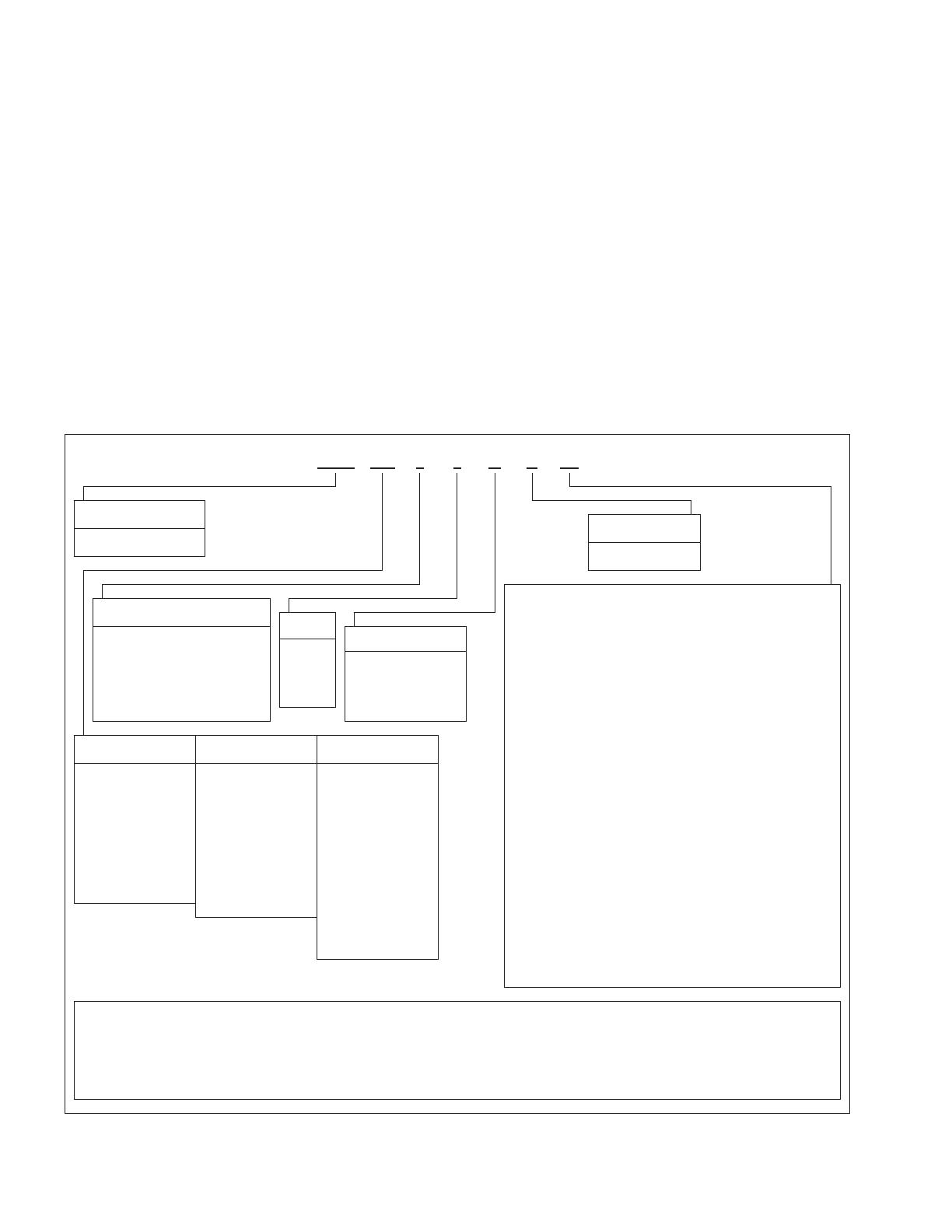
Catalog/Style Numbering
Eaton HMAX IntelliPass and IntelliDisconnect Catalog Number Matrix
HMX 011 3 4 N A P3
Product:
Software Options:
HMX = HVAC Drive (VT)
A - Standard
Intellipass/Options:
00 =None
P3 = Drive Isolation Fuses
(for FS 4-7 not available with M1, P6 or PE options)
P6 = Drive Isolation Contactor includes drive test switch
(For FS 4-7 not available with M1, P3 or PE options)
L4 = Pilot Lights (not available with M1)
M1 = Manual Bypass - includes pilot lights and Isolation contactor (not
available with any other wired option)
IS = Isolation Switch not available with M1, P6 or PE options
SA = Space Heater w/Xformer (Type 3R only)
K9 = Aux Contacts
Intellidisconnect Options:
00 = None
P3 = Drive Isolation Fuses
PE = Drive Output contactor
L3 = HMAX Pilot Lights
SA = Space Heater w/Xformer (Type 3R only)
K9 = Aux Contacts
Extended I/O Options in Slot D & E:
B1 = 6 DI or DO, 1 ext +24V DC/EXT +24V DC Programmable
B2 = 1 RO (NC/NO), 1 RO (NO), 1 Thermistor
B4 = 1 AI (mA isolated), 2 AO (mA isolated)
B5 = Card-3 Relay Dry Contact
B9 = 1 RO (NO), 5 DI 42 – 240V AC Input
BF = Expander IO - 1*AO, 1*DO, 1*RO
I/O Options in Slot B
F2 = 2 relay and 1 Thermistor- not available with L3/L4 Pilot light
option replaces standard Relay1 pcb in Slot B and Fault Relay function
Optional Communications in Slot D & E:
C4 = OPTC4: Lonworks
Enclosure/Style:
Voltage:
3 = IntelliPass NEMA Type 1
4 = IntelliPass NEMA Type 12
5 = IntelliPass NEMA Type 3R
A = IntelliDisconnect NEMA Type 1
B = IntelliDisconnect NEMA Type 12
C = IntelliDisconnect NEMA Type 3R
Braking:
1 = 208V
2 = 230V
4 = 480V
5 = 575V
N = No Brake Chopper
(Low Overload)
B = Internal Brake
Chopper Low
NEC 208 Volts: NEC 230 Volts: NEC 480 Volts:
4D6 = 4.6 Amp = 1.0 HP
7D5 = 7.5 Amp = 2 HP
011 = 11 Amp = 3 HP
017 = 17 Amp = 5 HP
025 = 24 Amp = 7.5 HP
031 = 31 Amp = 10 HP
047 = 47 Amp = 15 HP
060 = 60 Amp = 20 HP
075 = 75 Amp = 25 HP
088 = 88 Amp = 30 HP
4D2 = 4.2 Amp = 1.0 HP
6D8 = 6.8 Amp = 2 HP
9D6 = 9.6 Amp = 3 HP
016 = 16 Amp = 5 HP
022 = 22 Amp = 7.5 HP
028 = 28 Amp = 10 HP
042 = 42 Amp = 15 HP
054 = 54 Amp = 20 HP
068 = 68 Amp = 25 HP
080 = 80 Amp = 30 HP
104 = 104 Amp = 40 HP
2D1 = 2.1 Amp = 1 HP
3D4 = 3.4 Amp = 2 HP
5D6 = 5.6 Amp = 3 HP
7D6 = 7.6 Amp = 5 HP
011 = 11 Amp = 7.5 HP
014 = 14 Amp = 10 HP
021 = 21 Amp = 15 HP
027 = 27 Amp = 20HP
034 = 34 Amp = 25 HP
040 = 40 Amp = 30 HP
052 = 52 Amp = 40 HP
065 = 65 Amp = 50 HP
077 = 77 Amp = 60 HP
096 = 96 Amp = 75 HP
Notes:
All Boards are Varnished
Battery Included in all drives for real time clock
EMC = EMC C2 Standard
Graphic keypad on all drives
Bypass & HOA Keypad
On Board Base RS485 Communications:
BACnet MS/TP = MS/TP = Master Slave / Token Protocol (Universal BACnet)
RS 485 ModbusRTU RS485, ASCII or RTU, remote terminal unit 32 Nodes
On Board Ethernet Based Communications:
BACnet/IP Ethernet Industrial Protocol
M = Modbus/TCP Transmission Control Protocol (Ethernet Based) Note
All Boards are Varnished
4
General
H-Max Series Drives IntelliPass®/IntelliDisconnect® IL04008003E April 2013 www.eaton.com
Identi cation
Unit ID labels
H-Max IntelliPass/IntelliDisconnect Carton Label
H-Max IntelliPass/IntelliDisconnect Nameplate
IND.CONT. E
Q
.
77Y
6
www.eaton.com
Enclosure Type:
Short Circuit Ratings:
See IS Manuals for more information:
99776655
Schematic:
T
HMX01131NAIS
Catalog No:
Max Ambient Temp:
Order No:
1
Intellipass
Field installed conductors must be copper rated at 75°C.
Input:
Output:
Max HP:
0-208VAC 0-320Hz 10.6A
208VAC 50/60Hz 10.6A
IL04008003E
3 Hp @ 208VAC 10.6A
Control: 24VDC
40C
H-Max Series VFD
Style No:
3-3188-026A
285447-0008
MN04008005E
and
65KA @ 208VAC
654321
Assembled in USA
Serial No:
120418
Options: IS
Eaton
Catalog Number
Factory options
Eaton
Order & Serial
Numbers
Eaton
Style Number
Ratings
Schematic and
Instruction Manuals
Eaton
Catalog Number
Factory options
Eaton
Order Number
Eaton
Style Number
Ratings
Assembled in USA123456789012
123456
-40C to 70C (-40F to 158F)
3-3188-026A

Style No:
Storage Temp:
Max HP:
Order No:
7
JOB# 2000 AIR UNIT # 1
Cust.Ref No:
www.eaton.com
Options: IS
30-16557
5
Identi cation
H-Max Series Drives IntelliPass®/IntelliDisconnect® IL04008003E April 2013 www.eaton.com
Use table below to determine enclosure size and frame size based on Hp.
Enclosure Size and drive Frame size Indenfication
Volts Hp Current Drive Size Standard Enclosure
Type 1/12
3R and Oversize
Enclosure type 1/12
208 1 4.6
4 Size 4
A
2 7.5
3 10.6
230 1 4.2
2 6.8
3 9.6
480Y/277 1 2.1
2 3.4
3 4.8
5 7.6
7.5 11
208 5 16.7
5 Size 5
7.5 24.2
10 30.8
230 5 15.2
7.5 22
10 28
480Y/277 10 14
15 21
20 27
208 15 46.2
6 Size 6 B
230 15 42
480Y/277 25 34
30 40
40 52
208 20 59.4 6
Size 7 C
25 74.8
7
30 88
230 20 54 6
25 68
7
30 80
40 104
480 50 65
60 77
75 96
6
Identi cation
H-Max Series Drives IntelliPass®/IntelliDisconnect® IL04008003E April 2013 www.eaton.com
Components
IPass and IDisc Typical Component locations.
Typical Component Locations
H-Max
TM
Series
®
Intellipass
®
Active Energy Control
An Eaton Green Solution
23
32
4
4
7
Identi cation
H-Max Series Drives IntelliPass®/IntelliDisconnect® IL04008003E April 2013 www.eaton.com
Components
IPass and IDisc Typical Component locations.
8
Identi cation
H-Max Series Drives IntelliPass®/IntelliDisconnect® IL04008003E April 2013 www.eaton.com
Factory Wired Options
The Intellpass and IntelliDisconnect can be supplied with serveral factory wired power options. The sections below describe
the options.
Options
HMAX Option Matrix IPass IDisc
P3 - Drive Isolation Fuses X X
P6 - Drive Isolation Contactor includes manual switch X N/A
PE - Drive Output contactor N/A X
IS - Isolation Switch X N/A
SA - Space Heater (3R only) X X
K9 - Aux Contacts X X
M1 - Manual Bypass includes L4 and drive isolation contactor and door switch X N/A
L3 - H-Max Pilot Lights N/A X
L4 - H-Max Pilot Lights X N/A
P3- Drive Isolation Fuses
This option is available for both the IntelliPass and IntelliDisconnect designs 208/230V up to 30Hp and 480V models up to 75 hp.
3 Power Fuses are supplied wired to the Drive input. They are provided between the disconnect device and drive. The fuses
are not used in the bypass mode. The fuses are for drive protection only. They are listed, Class CC or Special Purpose Fuse
cube fuses sized according to the following table. This option cannot be used with IS Isolation switch or P6 isolation contac-
tor options. See IntelliDisconnnect or Typical IntelliPass schematic.
Hp Rating and Fuse Rating (A)
HP 208 V Fuse 230 V Fuse 460 V Fuse
1 6 6 5
2 12 12 6
3 20 20 8
5 25 25 12
7.5 30 30 20
10 45 45 25
15 60 60 30
20 80 80 45
25 90 90 45
30 100 100 50
40 N/A N/A 60
50 N/A N/A 80
60 N/A N/A 90
75 N/A N/A 100
9
Factory Wired Options
H-Max Series Drives IntelliPass®/IntelliDisconnect® IL04008003E April 2013 www.eaton.com
CCC Fuses (P3 option)
Cube Fuses (P3 option)
P3 Drive Fuse Option
10
Factory Wired Options
H-Max Series Drives IntelliPass®/IntelliDisconnect® IL04008003E April 2013 www.eaton.com
P6 – Drive Isolation Contactor includes Drive test switch
This option is only available on the IntelliPass models. An input contactor is supplied wired to the drive input and a manual
2 position selector switch is provided to control the contactor. The switch is located inside the enclosure on the door. The
enclosure door must be opened to operate this switch. See typical IntelliPass schematic.
The contactor removes main power from the Drive. The Drive display and logic will remain active because of the separate
24Volt power supply, but the Drive will not run. The Drive Keypad is still powered and the bypass feature remains operational
and the motor can be run in bypass using the keypad. The input contactor “I” is energized at all times while in the drive
mode if the door mounted selector switch us in the on position. This option cannot be used with M1 Manual Bypass, IS
Isolation switch or P3 fuse options.
P6 Drive Isolation Contactor Option Typical View Frames 4 - 6 (FR4 Shown)
Switch on inside of door
Input contactor
23
32
4
4
11
Factory Wired Options
H-Max Series Drives IntelliPass®/IntelliDisconnect® IL04008003E April 2013 www.eaton.com
IS - Drive Isolation Switch
This option is available on the IntelliPass models only. This is an MMP or molded case switch, installed at the input of the
Drive to be used as a switch only to isolate the drive from input power. The IntelliPass door must be opened to operate this
switch – a thru the door operator is not supplied. The switch removes main power from the Drive. The Drive display and logic
will remain active because of the separate 24Volt power supply, but the drive will not run. The drive Keypad is still powered
and the bypass feature remains operational and the motor can be run in bypass using the keypad. This option cannot be used
with P3 or P6 options. See Typical IntelliPass Schematic.
Drive Isolation Switch Option IS
23
32
4
4
12
Factory Wired Options
H-Max Series Drives IntelliPass®/IntelliDisconnect® IL04008003E April 2013 www.eaton.com
M1 - Manual Bypass (forced) Switch
This option is available on the IntelliPass models only. This option includes an input contactor “I”, L4 pilot light option and a 3
position door mounted selector switch - marked Drives/Off/Bypass. This switch manually overrides the Bypass control from
the system (keypad) and puts unit in bypass or in an OFF mode. See IntelliPass Schematic with M1 option.
When the door switch is in the Drive position, the H-Max Drive logic controls the motor and the keypad selects the operation
(Drive or Bypass), the control source and place (HOA, KEYPAD or Terminal block). The input contactor “I” is energized at all
times while in the drive mode.
When the door switch is moved to Bypass, three actions occur: 1) Drive input isolation contactor is forced open, 2) Drive
output contactor will be forced open and the bypass contactor will be forced closed. The motor will immediately start and run
full speed across the line regardless of the state of the system or drive.3) The Drive will be forced to the bypass mode and
the Keypad Display will show “Bypass”. When the switch is moved back the Drive position, Drive operation is restored and
the system may need to be restarted.
When the switch is in the off position neither the drive or bypass operation is possible. Moving the Switch to the off or
bypass position while the Drive is operating may cause the Drive to fault because the input power to the drive is removed by
the input contactor. See L4 for description/operation of the door mounted pilot lights.
Manual Bypass Option M1
H-Max
TM
Series
®
Intellipass
®
Active Energy Control
An Eaton G reen S olution
23
32
4
4
M1 Option
3R Versions have Bypass
switch located in Keypad
Enclosure
13
Factory Wired Options
H-Max Series Drives IntelliPass®/IntelliDisconnect® IL04008003E April 2013 www.eaton.com
PE- Drive Output contactor
This option is available for IntelliDisconnect models only. This option provides a contactor wired to the Drive output. The
motor is then wired to the contactor. The output contactor is controlled by the Drive so when the Drive is stopped the con-
tactor drops out and when the Drive is in a run mode, the output contactor is energized and connects the Drive to the motor.
A 24 volt power supply is also provided to power the contactor. Provisions for and external interlock is also provided. See
IntelliPass schematic with PE option.
IntelliDisconnect PE Output Contactor Option
PS
L
N
24V 2.5A
-
+
50-60Hz
100-240V~ 1.5A
DC OK
Adjust
SA - Space Heater Option (Type 3R enclosures only)
This option aids in preventing or reducing condensation from forming in the enclosure when the drive is inactive. A 120V
100W heater is installed in 3R enclosures size A & B and a 200W heater are installed in enclosure size C. A control trans-
former and fusing is also provided to power the heater. See schematics for more information. The heater includes a user
adjustable thermostat for variable temperature control and an internal fan. See pictures
SETTING THE THERMOSTAT
The heater is controlled by an adjustable thermostat. Set the thermostat to the desired temperature. It is recommended not
to exceed 75 F for most applications. The heater is active at all times when the main disconnect is closed including when in
the Drive, Off or Bypass operation. However, depending on the setting of the thermostat, the internal heat generated by the
system when in operation should be enough to turn off the heater. Generally the heater requires no maintenance since the
fan bearings are permanently lubricated and sealed.
14
Factory Wired Options
H-Max Series Drives IntelliPass®/IntelliDisconnect® IL04008003E April 2013 www.eaton.com
Heater
Control
Transformer
Heater Thermostat
Adjustment
Heater Fuses
See Schematic
15
Factory Wired Options
H-Max Series Drives IntelliPass®/IntelliDisconnect® IL04008003E April 2013 www.eaton.com
L3/L4 - HMAX Pilot Lights
The L3 option is available only on the IntelliDisconnect models and provides 3 door mounted pilot lights, 1 red, 1 white and 1
green. The L4 option is available on the IntelliPass models and provides 4 door mounted pilot lights: 1 red, 1 white, 1 green
and 1 amber.
H-Max
TM
Series
®
Intellipass
®
Active Energy Control
An Eaton Green Solution
L4 Option L3 Option
The white “Power On” light indicates that 24VDC power is active. However, Caution is advised if the light is not illuminated,
as this is may not be an indication that main power has been removed. If the light fails or the 24V power supply fails, main
power may still be present. Always follow proper safety procedures to determine the presence of main power on the unit
The red “Drive Fault” light indicates a Drive fault is present.
The green light indicates the system is commanded to run from the Drive and the Drive is in the “run” mode, the drive out-
put contactor is also energized if the PE option is supplied. The speed of the motor will depend on the Drive speed signal.
The motor may not be rotating if commanded at zero speed.
The amber light indicates the system has been commanded to run in bypass. The bypass contactor should be energized and
the motor running across the line.
16
Factory Wired Options
H-Max Series Drives IntelliPass®/IntelliDisconnect® IL04008003E April 2013 www.eaton.com
Plug in options
K9 Aux Contacts
This option adds 1 N.O. & N.C. auxiliary contacts to both the Drive output and bypass contactors for customer use.
K9 Aux Contact Applications
Product Frame Hp Voltage Qty Eaton P/N Description
IPass 4 ALL ALL 2 XTCEXFAC11 Aux NO, NC Contact, B/C frame Top Mount
IPass 5 ALL ALL 2 XTCEXFAC11 Aux NO, NC Contact, B/C frame Top Mount
IPass 6 ALL ALL 2 XTCEXFAG11 Aux NO, NC Contact, D/F/G frame Top Mount
IPass 7 ALL ALL 2 XTCEXFAG11 Aux NO, NC Contact, D/F/G frame Top Mount
IDisc 4 ALL ALL 1 XTCEXFAC11 Aux NO, NC Contact, B/C frame Top Mount
IDisc 5 ALL ALL 1 XTCEXFAC11 Aux NO, NC Contact, B/C frame Top Mount
IDisc 6 ALL ALL 1 XTCEXFAG11 Aux NO, NC Contact, D/F/G frame Top Mount
IDisc 7 ALL ALL 1 XTCEXFAG11 Aux NO, NC Contact, D/F/G frame Top Mount
17
Plug in options
H-Max Series Drives IntelliPass®/IntelliDisconnect® IL04008003E April 2013 www.eaton.com
Optional plug in PCBS
A number of plug in option cards are available. A maximum of 2 option cards may be factory installed in the control module
slots. Available options are shown in the table below.
Typical Plug in Option PCB
See the option manual included with each PCB for more information.
Also see H-Max Installation manual MN04008005E for more information on control wiring, control board layout and options
PCBs.
See option manual included with each PCB for more information also see H-Max Installation manual MN04008005E for more
information on control wiring and control board layout and options PCBs.
Dimensions & Mounting
The IntelliPass/IntelliDisconnect physical dims are based on the Enclosure frame size. See Table to determine the enclosure
frame size based on Hp and voltage.
Weights and lifting provisions are on the dimension section and with the drawing provided with the unit
Attach “load-rated” hooks or shackles to lifting eyes on back panel.
Always maintain a maximum of 45 degrees between the lifting cables and the vertical plane.
Do not pass ropes or cables through the lifting eyes as sharp edges may cause excessive wear and possible failure.
Select or adjust rigging lengths to compensate for unequal weight distribution of the load to keep unit in the upright
position.
Option
Brand
Config
VFD
Frame
Voltage
HP
Qty
P/N Style Number Description
B1 All All ALL ALL ALL 1 XMX-IO-B1-A 3-3131-0003A I/O Expander Card, 6 DI/DO, Slot D/E
B2 All All ALL ALL ALL 1 XMX-IO-B2-A 3-3131-0004A I/O Expander Card 2 x RO + Thermistor, Slot D/E
B4 All All ALL ALL ALL 1 XMX-IO-B4-A 3-3131-0005A I/O Expander Card 1 x AI, 2 x AO (isolated), Slot D/E
B5 All All ALL ALL ALL 1 XMX-IO-B5-A 3-3131-0006A I/O Expander Card 3 x RO, Slot D/E
B9 All All ALL ALL ALL 1 XMX-IO-B9-A 3-3131-0007A I/O Expander Card 1 x RO, 5 x DI (42-240VAC), Slot D/E
BF All All ALL ALL ALL 1 XMX-IO-BF-A 3-3131-0008A I/O expander Card, 1 x AO, 1 x DO, 1 x RO, Slot D/E
C4 All All ALL ALL ALL 1 XMX-COM-C4-A 3-3131-0009A LonWorks, Slot D/E
18
Dimensions & Mounting
H-Max Series Drives IntelliPass®/IntelliDisconnect® IL04008003E April 2013 www.eaton.com
STANDARD ENCLOSURE SIZE 4 TYPE 1/12
DIMENSIONS & MOUNTING
19
Dimensions & Mounting
H-Max Series Drives IntelliPass®/IntelliDisconnect® IL04008003E April 2013 www.eaton.com
STANDARD ENCLOSURE SIZE 5 TYPE 1/12
DIMENSIONS & MOUNTING
20
Dimensions & Mounting
H-Max Series Drives IntelliPass®/IntelliDisconnect® IL04008003E April 2013 www.eaton.com
  • Page 1 1
  • Page 2 2
  • Page 3 3
  • Page 4 4
  • Page 5 5
  • Page 6 6
  • Page 7 7
  • Page 8 8
  • Page 9 9
  • Page 10 10
  • Page 11 11
  • Page 12 12
  • Page 13 13
  • Page 14 14
  • Page 15 15
  • Page 16 16
  • Page 17 17
  • Page 18 18
  • Page 19 19
  • Page 20 20
  • Page 21 21
  • Page 22 22
  • Page 23 23
  • Page 24 24
  • Page 25 25
  • Page 26 26
  • Page 27 27
  • Page 28 28
  • Page 29 29
  • Page 30 30
  • Page 31 31
  • Page 32 32
  • Page 33 33
  • Page 34 34
  • Page 35 35
  • Page 36 36
  • Page 37 37
  • Page 38 38
  • Page 39 39
  • Page 40 40
  • Page 41 41
  • Page 42 42
  • Page 43 43
  • Page 44 44
  • Page 45 45
  • Page 46 46

Ask a question and I''ll find the answer in the document

Finding information in a document is now easier with AI