Supermicro AOM-CTG-i2SM-12 User manual
- Category
- Networking cards
- Type
- User manual

User's Guide
Revision 1.0
AOM-CTG-i2SM-12

User's Guide Revision 1.0
Release Date: August 4, 2020
Unless you request and receive written permission from Super Micro Computer, Inc., you may not
copy any part of this document.
Information in this document is subject to change without notice. Other products and companies
referred to herein are trademarks or registered trademarks of their respective companies or mark
holders.
Copyright © 2020 by Super Micro Computer, Inc.
All rights reserved.
Printed in the United States of America
The information in this user's guide has been carefully reviewed and is believed to be accurate. The
vendor assumes no responsibility for any inaccuracies that may be contained in this document, and
makes no commitment to update or to keep current the information in this user's guide, or to notify
any person or organization of the updates. Please Note: For the most up-to-date version of this
user's guide, please see our Website at www.supermicro.com.
Super Micro Computer, Inc. ("Supermicro") reserves the right to make changes to the product
described in this user's guide at any time and without notice. This product, including software and
documentation, is the property of Supermicro and/or its licensors, and is supplied only under a
license. Any use or reproduction of this product is not allowed, except as expressly permitted by
the terms of said license.
IN NO EVENT WILL SUPER MICRO COMPUTER, INC. BE LIABLE FOR DIRECT, INDIRECT,
SPECIAL, INCIDENTAL, SPECULATIVE OR CONSEQUENTIAL DAMAGES ARISING FROM THE
USE OR INABILITY TO USE THIS PRODUCT OR DOCUMENTATION, EVEN IF ADVISED OF
THE POSSIBILITY OF SUCH DAMAGES. IN PARTICULAR, SUPER MICRO COMPUTER, INC.
SHALL NOT HAVE LIABILITY FOR ANY HARDWARE, SOFTWARE, OR DATA STORED OR USED
WITH THE PRODUCT, INCLUDING THE COSTS OF REPAIRING, REPLACING, INTEGRATING,
INSTALLING OR RECOVERING SUCH HARDWARE, SOFTWARE, OR DATA.
Any disputes arising between the manufacturer and the customer shall be governed by the laws of
Santa Clara County in the State of California, USA. The State of California, County of Santa Clara
shall be the exclusive venue for the resolution of any such disputes. Supermicro's total liability for
all claims will not exceed the price paid for the hardware product.
FCC Statement: This equipment has been tested and found to comply with the limits for a Class A
digital device pursuant to Part 15 of the FCC Rules. These limits are designed to provide reasonable
protection against harmful interference when the equipment is operated in an industrial environment.
This equipment generates, uses, and can radiate radio frequency energy and, if not installed and
used in accordance with the manufacturer’s instruction manual, may cause harmful interference with
radio communications. Operation of this equipment in a residential area is likely to cause harmful
interference, in which case you will be required to correct the interference at your own expense.
California Best Management Practices Regulations for Perchlorate Materials: This Perchlorate
warning applies only to products containing CR (Manganese Dioxide) Lithium coin cells. “Perchlorate
Material-special handling may apply. See www.dtsc.ca.gov/hazardouswaste/perchlorate”.
WARNING: This product can expose you to chemicals including
lead, known to the State of California to cause cancer and birth
defects or other reproduc�ve harm. For more informa�on, go
to www.P65Warnings.ca.gov.
!

Preface
About this User's Guide
This user's guide is written for system integrators, IT technicians, and
knowledgeable end users. It provides information for the installation and use of the
AOM-CTG-i2SM-12 package.
About this Add-on Card
The AOM-CTG-i2SM-12 10 Gigabit Ethernet Adapter is the most compact and scal-
able 10G Ethernet adapter for today’s demanding data center environments. Based
on the Intel® 10GbE network controller 82599ES, it addresses the demanding needs
of the next-generation data center by providing features for virtualization, exibility
for LAN and SAN networking, and proven reliable performance. With NC-SI built-in,
this adapter provides connection for both data and remote management to simplify
cabling need in a data center. The AOM-CTG-i2SM-12 is designed in a proprietary
and small MicroLP form factor to t Supermicro MicroCloud 12-node system.
Note: AOM-CTG-i2SM-12 consists of the AOM-CTG-i2SM add-on card,
the AOM-RSC-E8R riser card, and Drive Kit MCP-240-93913-0N.
An Important Note to the User
All images and layouts shown in this user's guide are based upon the latest PCB
Revision available at the time of publishing. The card you have received may or
may not look exactly the same as the graphics shown in this user's guide.
Returning Merchandise for Service
A receipt or copy of your invoice marked with the date of purchase is required before
any warranty service will be rendered. You can obtain service by calling your ven-
dor for a Returned Merchandise Authorization (RMA) number. When returning the
motherboard to the manufacturer, the RMA number should be prominently displayed
on the outside of the shipping carton, and the shipping package is mailed prepaid
or hand-carried. Shipping and handling charges will be applied for all orders that
must be mailed when service is complete. For faster service, you can also request
a RMA authorization online (http://www.supermicro.com/RmaForm/).
Preface
iii

iv
Super AOM-CTG-i2SM Add-on Card User's Guide
This warranty only covers normal consumer use and does not cover damages in-
curred in shipping or from failure due to the alternation, misuse, abuse or improper
maintenance of products.
During the warranty period, contact your distributor rst for any product problems.
Conventions Used in the User's Guide
Pay special attention to the following symbols for proper system installation and to
prevent damage to the system or injury to yourself:
Warning: Important information given to ensure proper system installation
or to prevent damage to the components or injury to yourself.
Note: Additional information given to dierentiate between various models
or provides information for correct system setup.
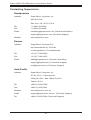
Naming Convention

v
Preface
Networking Adapter List

Contacting Supermicro
Headquarters
Address: Super Micro Computer, Inc.
980 Rock Ave.
San Jose, CA 95131 U.S.A.
Tel: +1 (408) 503-8000
Fax: +1 (408) 503-8008
Email: [email protected] (General Information)
[email protected] (Technical Support)
Website: www.supermicro.com
Europe
Address: Super Micro Computer B.V.
Het Sterrenbeeld 28, 5215 ML
's-Hertogenbosch, The Netherlands
Tel: +31 (0) 73-6400390
Fax: +31 (0) 73-6416525
Email: [email protected] (General Information)
[email protected] (Technical Support)
[email protected] (Customer Support)
Asia-Pacic
Address: Super Micro Computer, Inc.
4F, No. 232-1, Liancheng Rd.
Chung-Ho Dist., New Taipei City 235
Taiwan, R.O.C.
Tel: +886-(2) 8226-3990
Fax: +886-(2) 8226-3991
Website: www.supermicro.com.tw
Email: [email protected] (Technical Support)
Tel: +886-(2) 8226-5990 (Technical Support)
Super AOM-CTG-i2SM Add-on Card User's Guide
vi

Table of Contents
Preface
Chapter 1 Overview
1-1 Overview ......................................................................................................... 1-1
1-2 Key Features ................................................................................................... 1-1
1-3 Specications .................................................................................................. 1-1
1-4 Parts List ......................................................................................................... 1-4
Chapter 2 Hardware Components
2-1 Add-On Card Image and Layout ..................................................................... 2-1
2-2 Connectors ...................................................................................................... 2-3
Chapter 3 Installation
3-1 Static-Sensitive Devices .................................................................................. 3-1
3-2 Add-On Card Brackets .................................................................................... 3-2
3-3 Before Installation ........................................................................................... 3-3
3-4 Installing the Add-on Card .............................................................................. 3-3
3-5 Installing Drivers on Windows ......................................................................... 3-4
3-6 Installing Drivers on Linux ............................................................................... 3-5
v
Preface

Chapter 1: Overview
1-1
Chapter 1
Overview
1-1 Overview
Congratulations on purchasing your add-on card from an acknowledged leader in
the industry. Supermicro products are designed with the utmost attention to detail
to provide you with the highest standards in quality and performance. For product
support and updates, please refer to our website at http://www.supermicro.com/
products/nfo/networking.cfm#adapter.
1-2 Key Features
The key features of this add-on card include the following:
• Dual 10GbE SFP+ connectors
• MicroLP form factor
• Intel
®
QuickData Technology
• VMDq and PC-SIG SR-IOV for virtualized environments
• Supports both Direct Attach Copper (DAC) and ber cables
• RoHS compliant 6/6
• NC-SI for remote management
1-3 Specications
General
• Intel
®
82599ES 10GbE controller
• MicroLP form factor
• Dual SFP+ ports

1-2
AOM-CTG-i2SM-12 Add-on Card User's Guide
• Load balancing on multiple CPUs
• Intel
®
PROSet Utility for Windows
®
Device Manager
I/O Features
• Direct Cache Access (DCA) to avoid cache misses
• MSI-X support to minimize the overhead of interrupts, allowing load-balancing
between multiple cores/CPUs
• Tx/Rx IP, SCTP, TCP and UDP checksum ooading capabilities (IPv4, IPv6)
• Receiving and transmision of side scaling for Windows environments and scal-
able I/O for Linux environments
Virtualization Features
• Virtualization support such as VMDq, Next-Generation VMDq (64 queues per
port)
• PC-SIG SR-IOV implementation (64 virtual functions per port)
• Advanced packet ltering
• VLAN support to allow creation of multiple VLAN segments
• VXLAN through Software
Manageability Features
• Preboot eXecution Environment (PXE) support
• Simple Network Management Protocol (SNMP) and Remote Network Monitoring
(RMON) statistics counters
• iSCSI remote boot
• NC-SI for remote management
• Asset Management support on Supermicro
®
platforms

Chapter 1: Overview
1-3
• Controller asset tags such as part number, revision, serial number and MAC
addresses
Advanced Software Features
• Teaming support
• IEEE 802.3ad (link aggregation control protocol)
• IEEE 802.1Q VLANs
• IEEE 802.3 2005 ow control support
OS Support
• Windows Server
• Windows
• RedHat Linux
• SUSE Linux
• FreeBSD
• UEFI
• VMware
Cables Support
• SFP+ Direct Attach Copper cables
• Fiber-optic cables (with required optional SFP+ transceivers)
Power Consumption
• Maximum power consumption: 7W

1-4
AOM-CTG-i2SM-12 Add-on Card User's Guide
Operating Conditions
• Operating temperature: 0°C to 55°C (32°F to 131°F)
• Storage temperature: -40°C to 70°C (-40°F to 158°F)
• Storage humidity: 90% non-condensing relative humidity at 35°C
Physical Dimensions
• Card PCB dimensions: 113mm (4.45in) x 49mm (1.93in) (L x W)
Supported Platforms
• 5039MC-H12TRF (X11SCE-F)
• 5039MS-H12TRF (X11SSE-F)
Add-on Card Part Number Description
Add-on Card AOM-CTG-i2SM MicroLP 2-Port 10GbE SFP+ adapter
Riser Card AOM-RSC-E8R
MicroLP Riser Card for MicroCloud 12 node
Bracket MCP-240-93913-0N
MicroLP bracket for MicroCloud 12 node
Please note that this product is sold only as part of an integrated solution with
Supermicro server systems.
1-4 Parts List

Chapter 2: Hardware Components
2-1
Chapter 2
Hardware Components
2-1 Add-On Card Image and Layout
The AOM-CTG-i2SM-12 Image
1. Intel
®
82599ES 10GbE controller
2. JSFP1 (Connector Cage)
3. SFP1 Connector
4. SFP2 Connector

2-2
AOM-CTG-i2SM-12 Add-on Card User's Guide
JSFP1
MH2
MH3
SFP2
SFP1
MH1
REV:1.00
AOM-CTG-i2SM
DESIGNED IN USA
The AOM-CTG-i2SM-12 Layout
1. Intel
®
82599ES 10GbE controller
2. JSFP1 (Connector Cage)
3. SFP1 Connector
4. SFP2 Connector
3
1
2
4

Chapter 2: Hardware Components
2-3
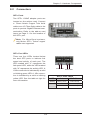
2-2 Connectors
SFP+ Ports
Two SFP+ 10GbE adapter ports are
located on the add-on card. Connect
a Direct Attach Copper Twin Axial
cable or an LC Fiber-Optic cable to the
ports to provide Gigabit Ethernet com-
munication. Refer to the add-on card
layout on Page 2-1 for the location of
the SFP+ port.
Note: For MicroCloud systems,
only Molex SFP+ Twinax copper
cables are supported.
Port 2 LED
SFP+ Port LEDs
There are four LEDs located below
the dual SFP ports to indicate link
speed and activity of each port. The
LED marked with "L" represents the
link speed LED, while the LED marked
with "A" represents the activity LED. A
10Gb connection is indicated by a solid
or blinking green LED. A 1Gb connec-
tion is indicated by a solid or blinking
yellow LED. See the table at right for
more information.
SFP+ Port LEDs
LED Color Denition
Activity Blinking Green 10Gb/s Activity
Link Solid Green 10Gb/s Link Speed
Solid Yellow 1Gb/s Link Speed
Port 1 LED
Port 1 Port 2
Port 1 Port 2

3-1
Chapter 3: Installation
Chapter 3
Installation
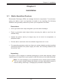
3-1 Static-Sensitive Devices
Electrostatic Discharge (ESD) can damage electronic com ponents. To avoid dam-
aging your add-on card, it is important to handle it very carefully. The following
measures are generally sucient to protect your equipment from ESD.
Precautions
• Use a grounded wrist strap designed to prevent static discharge.
• Touch a grounded metal object before removing the add-on card from the
antistatic bag.
• Handle the add-on card by its edges only; do not touch its components, or
peripheral chips.
• Put the add-on card back into the antistatic bags when not in use.
• For grounding purposes, make sure that your system chassis provides excellent
conductivity between the power supply, the case, the mounting fasteners and
the add-on card.
Unpacking
The add-on card is shipped in antistatic packaging to avoid static damage. When
unpacking your component or your system, make sure that you are static protected.
Note: To avoid damaging your components and to ensure proper installa-
tion, be sure to always connect the power cord last, and always remove it
before adding, removing or changing any hardware components.

3-2
AOM-CTG-i2SM-12 Add-on Card User's Guide
Note: For 2U systems, install the I/O bracket to the add-on card before
installing the card inside the system.
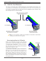
Removing/Installing the IO Bracket
Refer to the illustration at right for the following
instructions on removing/installing the I/O bracket.
To remove the I/O bracket: Loosen and remove
the I/O bracket screw, then gently pull the bracket
away from the add-on card.
To install the I/O bracket: Position the bracket so
that the I/O cut-outs align with the connectors on
the add-on card. Connect the I/O bracket to the
add-on card, making sure that the screw hole in
the PCB bracket and the I/O bracket are aligned.
Secure the bracket to the add-on card using the
I/O bracket screw.
BKT-0056L (Factory installed
MicroLP PCB bracket)
BKT-0061L (Factory
installed I/O bracket)
BKT-0062L (Customer installed
I/O bracket for 2U system)
For 2U System
I/O bracket
PCB
bracket
I/O bracket
screw
For 1U System
3-2 Add-On Card Brackets
The add-on card ships with a PCB bracket that is pre-installed at the factory. For
1U systems, an I/O bracket is also pre-installed on the card. For 2U systems, the
I\O bracket is bundled with the card and must be installed by the customer. See
the drawings below for bracket details.

3-3
Chapter 3: Installation
3-3 Before Installation
To install the add-on card properly, be sure to follow the instructions below.
1. Power down the system.
2. Remove the power cord from the wall socket.
3. Use industry standard anti-static equipment (such as gloves or wrist strap)
and follow the instructions listed on Page 3-1 to avoid damage caused by
ESD.
4. Familiarize yourself with the server, motherboard, and/or chassis documenta-
tion.
5. Conrm that your operating system includes the latest updates and hotxes.
3-4 Installing the Add-on Card
Follow the steps below to install the add-on card into your system.
1. Remove the server cover and, if necessary, set aside any screws for later
use.
2. Remove the add-on card slot cover. If the case requires a screw, place the
screw aside for later use.
3. Position the add-on card in the slot directly over the connector, and gently
push down on both sides of the card until it slides into the PCI connector.
4. Secure the add-on card to the chassis. If required, use the screw that you
previously removed.
5. Attach any necessary external cables to the add-on card.
6. Replace the chassis cover.
7. Plug the power cord into the wall socket, and power up the system.

3-4
AOM-CTG-i2SM-12 Add-on Card User's Guide
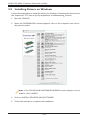
Note: If the FOUND NEW HARDWARE WIZARD screen displays on your
system, click CANCEL.
3. Click on INSTALL DRIVERS AND SOFTWARE.
4. Follow the prompts to complete the installation.
3-5 Installing Drivers on Windows
Follow the steps below to install the drivers for Windows. Download the drivers from
the Supermicro FTP site at ftp://ftp.supermicro.com/Networking_Drivers/.
1. Run the CDR-NIC.
2. When the SUPERMICRO window appears, click on the computer icon next to
the product model.

3-5
Chapter 3: Installation
3-6 Installing Drivers on Linux
Follow the steps below to install the driver to a Linux system.
1. Download the driver from the Supermicro CDR-NIC LAN driver CD, the Intel
Support website that contains the latest driver, or go to the Supermicro site at:
ftp://ftp.supermicro.com/Networking_Drivers/CDR-NIC_1.62_for_Add-on_NIC_
Cards/Intel/. Go to the following directory LAN/PROXGB/LINUX
2. Choose the desired Intel driver package le from LAN/PROXGB/LINUX.
3. Copy the driver to the directory of your choice. For example:
/home/username/ixgbe
or
/usr/local/src/ixgbe
4. Untar/unzip archive, where <x.x.x> is the version number for the driver tar le:
tar zxf ixgbe-x.x.x.tar.gz
5. Change to the driver src directory, where <x.x.x> is the version number for
the driver tar:
cd ixgbe-x.x.x/src/
make install
This is the process to install the Linux driver to your system. For more driver instal-
lation information, please refer to the Intel Support Website.

(Disclaimer Continued)
The products sold by Supermicro are not intended for and will not be used in life support systems,
medical equipment, nuclear facilities or systems, aircraft, aircraft devices, aircraft/emergency com-
munication devices or other critical systems whose failure to perform be reasonably expected to result
in signicant injury or loss of life or catastrophic property damage. Accordingly, Supermicro disclaims
any and all liability, and should buyer use or sell such products for use in such ultra-hazardous ap-
plications, it does so entirely at its own risk. Furthermore, buyer agrees to fully indemnify, defend
and hold Supermicro harmless for and against any and all claims, demands, actions, litigation, and
proceedings of any kind arising out of or related to such ultra-hazardous use or sale.
-
 1
1
-
 2
2
-
 3
3
-
 4
4
-
 5
5
-
 6
6
-
 7
7
-
 8
8
-
 9
9
-
 10
10
-
 11
11
-
 12
12
-
 13
13
-
 14
14
-
 15
15
-
 16
16
-
 17
17
-
 18
18
-
 19
19
-
 20
20


Supermicro AOM-CTG-i2SM-12 User manual
- Category
- Networking cards
- Type
- User manual
Ask a question and I''ll find the answer in the document
Finding information in a document is now easier with AI
Related papers
-
Supermicro AOC-S25G-i2S User manual
-
Supermicro AOC-CTG-I2S User manual
-
Supermicro AOC-MTGN-i2S User manual
-
-
-
-
-
Supermicro AOC-CTGS-i2T User manual
-
-
Supermicro AOC-CTG-I1S User manual
Other documents
-
AMX MAX-AOM User manual
-
-
 AquaPure AQUAPURE-AP-DW70 Operating instructions
-
 Gbord EN-101 User manual
-
Intel XL710QDA1BLK Datasheet
-
DirekTronik 180-1812 User guide
-
Spectrum Industries 68153D Assembly Instructions
-
-
Savant AOM-BAL16-00 Reference guide
-
CARLO GAVAZZI DEB71DM24A30 Installation guide

