KNLU Series (Koren) LED Under Cabinet Fixture
Models KNLU9, KNLU14, KNLU22, KNLU32 & KNLU40 Plug-in or Hard Wire, Linkable
Page 1 of 3 8060793 R3
Safety Precautions
Read all safety precautions and installation instructions carefully before installing or servicing this fixture. Failure to comply with these instructions could result in potentially fatal
electric shock and/or property damage.
It is recommended that a qualified electrician perform all wiring. This fixture must be wired in accordance with all national and local electrical codes.
Do not handle any energized fixture or attempt to energize any fixture with wet hands or while standing on a wet or damp surface or in water.
This fixture is designed for use in a 120VAC, 60Hz fused circuit. This fixture can be dimmed down to 10% of full scale using a compatible TRIAC (forward-phase or leading-edge) or
ELV (reverse-phase or trailing-edge) dimmer. This Fixture is dimmable in the high (II) setting only.
Make sure that the power source conforms to the requirements of the fixture. (See labels on the fixture housing).
To reduce the risk of electrical shock, and to assure proper operation, this fixture must be adequately grounded. To accomplish proper grounding, there must be a separate ground wire
(green) contact between this fixture and the ground connection of your main power supply panel.
This fixture is intended to be used for general indoor lighting in dry or damp locations. Linkable total wattage is 200 watts.
Disclaimer
Changes or modifications not expressly approved by the party responsible for compliance could void the user’s authority to operate the equipment. NOTE: This equipment has been
tested and found to comply with the limits for a Class B digital device, pursuant to Part 15 of the FCC Rules and Canadian ICES-005 (B) / NMB-005 (B). These limits are designed to
provide reasonable protection against harmful interference in a residential installation. This equipment generates uses and can radiate radio frequency energy and, if not installed and used
in accordance with the instructions, may cause harmful interference to radio communications. However, there is no guarantee that interference will not occur in a particular installation. If
this equipment does cause harmful interference to radio or television reception, which can be determined by turning the equipment off and on, the user is encouraged to try to correct the
interference by one or more of the following measures:
• Reorient or relocate the receiver antenna.
• Increase the separation between the equipment and receiver.
• Connect the equipment into an outlet on a circuit different from that to which the receiver is connected.
• Consult with the dealer or an experienced radio/TV technician for help.
Any modifications to this fixture may void the warranty and interfere with the safe operation of the luminaire.
Operation is subject to the following two conditions: (1) this device may not cause interference, and (2) this device must accept any interference, including interference that may cause
undesired operation of the device.
Assembly Instructions
1. Preparation for Installation
A. Disconnect electrical power before installing or servicing any part of this
fixture.
B. Place fixture on a clean flat surface.
C. Determine input power connection method (Cord, Hardwire or Link) and follow
corresponding directions below.
2. Cord to Outlet Installation
(Skip this step if using Hardwire or Link-to-Fixture Installation)
A. Fixture must be mounted within 5’ of an outlet. Power cord NOT included
(Sold Separately).
B. Connect Cord to fixture by snapping the quick connect end of the cord to the
corresponding connector in the end of the fixture marked “IN”. The cord will
only connect to the “IN” connector so make the right connector is identified.
Do not force the connection, it should snap in easily.
C. Follow the directions for Mounting below.
D. Once Mounting is completed, plug the cord into the outlet.
E. The unit can now be turned on with the Power switch (7a). By flipping the
switch (7a) select between one of the 3 modes (Lo, Off, Hi ).
Switch (6a) is used to change the color temperature of light
delivered 2700K, 3000K & 4000K CCT respectively.
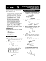
3. Hardwire Installation Preparation (Figure 2)
(Skip this step if using Cord to Outlet or Link-to-Fixture Installation
to Power Unit)
A. Remove appropriate 3/8” diameter knockout for supply wiring entry
and remove plug (1).
B. Determine appropriate connector:
i) Cable connector is included.
ii) Flexible conduit BX (AC) 3/8”trade size cable (not included).
iii) Anti-short bushing (not included).
C. Insert cable connector (3) into the housing open hole. Screwing it
into the nut in the bracket (4).
D. Determined the length of BX cable and add about 5” or an
appropriate length for the stripping purposes. Cut the required
length of the cable. Trim away the insulation. Push the exposed
wires (hot, neutral and ground) through the anti-short bushing and
slide this bushing all the way down to the exposed wires until it is
snug up against the armor.
E. Remove screw holding on back cover plate and remove cover (5)
and discard.
F. (See Hardware Installation Completion) for image (6)
G. Snap bracket into main housing and tighten screw back in to hold
into position (7).