Product description
Identification
Motor code
3
13
Lenze • BA 33.0006 • 5.1
Example M C A 21X25 -RS0 B0 -A38R -ST5
S00N
-R0SU
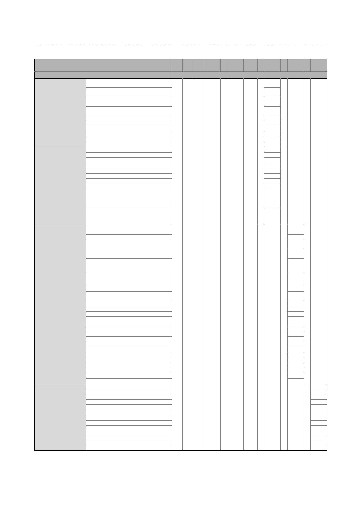
Meaning Type Motor code
Design Standard flange form A/FF with through hole, cyl.
shaft without keyway
-
A
Standard flange form A/FF with through hole, cyl.
shaft with keyway
B
Standard flange form C/FT with threaded holes, cyl.
shaft without keyway
C
Standard flange form C/FT with threaded holes, cyl.
shaft with keyway (standard attachment)
N
Same as version A except that flange is large F
Same as version B except that flange is large G
Same as version C except that flange is large U
Same as version N except that flange is large V
Foot mounting B3 without keyway O
Foot mounting B3 with keyway P
Shaft Shaft 11x23 (MCS06) 11
Shaft 14x30 (MCS09; MCA 10) 14
Shaft 19x40 (MCS12; MCA13) 19
Shaft 24x50 (MCS14; MCA14, 17) 24
Shaft 28x60 (MCS19; MCA19) 28
Shaft 38x80 (MA22, 22) 38
Shaft 55x110 (MA26) 55
Concentricity/vibrational
severity/direct gearbox
attachment
Concentricity/vibrational severity N, R or V
Direct gearbox attachment: Motor without pinion
for mounting on open gearbox with pinion; flange
for direct gearbox attachment without intermediate
cover, with tapered hollow shaft
Z0X
Direct gearbox attachment: Motor without pinion
for mounting on open gearbox with pinion; flange
for direct gearbox attachment with intermediate
cover, with tapered hollow shaft
Y0X
Electrical connection Separate circular connectors for power/brake,
encoder/thermal detector, fan
-
ST
Shared rectangular connector for power, encoder... SQ
Separate terminal boxes for power/brake,
encoder/thermal detector/fan
KK
Separate terminal boxes for power/brake, blower
circular connectors for encoder, thermal detector
KG
Terminal box for power+brake; circular connector
for encoder and thermal detector; circular connector
for blower
KS
Circular connector for power+brake; circular
connector for encoder+thermal detector; terminal
box for fan
SK
Enclosure IP23 2
IP54 without shaft sealing ring (except for direct
gearbox attachment)
5
IP65 with shaft sealing ring 6
IP64 (A-flange, without shaft sealing ring) / IP65 A
IP54 with shaft sealing ring (A-end bearing, oil-tight) B
IP54 with shaft sealing ring, double lip (A-end
bearing dust-tight)
C
Cooling Natural ventilation / without fan D
Natural ventilation / without fan S00
Blower 230V; AC; 1N; filter F1F
Blower 400V; AC; 3N; filter F3F
Blower 480V; AC; 3N FWO
Blower 230V; AC; 1N F10
Blower 400V; AC; 3N F30
Blower 115V; AC; 1N F50
Blower 480V; AC; 3N; filter FWF
Load flywheel Without additional load flywheel N
With additional mass inertia J
Motor protection, temperature
protection
NC thermal contact
-
B
KTY + PTC (MCS09...19) D
KTY sensor; electronic nameplate E
KTY sensor R
KTY - TCO NC contact (standard MQA) T
Electronic nameplate Standard nameplate 0
Standard nameplate + electronic nameplate 1
Second nameplate supplied loose 2
Second nameplate supplied loose + electronic
nameplate
3
Colour/specification Colour: black S
Specification - UL design and CSA design, approval U
Specification - UL design, approval R


