Page is loading ...

1
PID-8CH-SSR Multi-Loop Controller Instruction Manual
1. Features:
1.1. 8 channels of temperature controls are packed into 160 x 80 x 110mm case
8 kinds of combinations of temperature set value, PID constant, alarm set value, etc.
1.1.Input Sensor Types
Thermocouple (temperature input): K, J, T, E, S
Resistance thermometer (temperature input): Pt100, CU50
1.2.Control Outputs
A control output can be a relay output, voltage output (for driving SSR), or current output, depending on
the model.
1.3.Adjusting PID Constants
Can be easily set the optimum PID constants by performing AT (auto-tuning) with the limit cycle method.
1.4.Standard Alarms
Can be output an alarm when the deviation, process value, set point, or manipulated value reaches a
specified value.
1.5.Use this controller within the following allowable range:
Allowable ambient temperature: −0 to +55 °C
Allowable ambient humidity: 5 to 85 % RH.
2. Dimensions:
h×w×d(Unit: mm) 160×80×85 Panel cutout 152×76
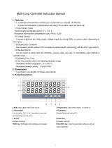
3. Parts Description:
1 ALM: lamp Lights when Event occurs 2 Output lamp: Lights when output is turned on
3 Channel key:
You can press ‘CH1~8’ for 3 seconds to enter into
corresponding channel menu.
4 PV display:
Displays Measured value (PV)
5 Up key:
Increase numerals.
6 Down key:
Decrease numerals
7Shift key: Shift digits when settings are changed. 8 Set (SET) key: Used for parameter calling up and set
value registration.

2
4. Terminal Arrangement:
5. Parameters
ID Symbol Name Manual Setting
range Ex-Factory
The public parameters(First level)
0 Lock Set data lock LOCK=18, Set data unlock
LOCK≠18, Set data lock. 0~50 18
1 TS Input type Cu50; Pt2 (pt100); K; E;J;T; S - -
2 ALP Alarm type
0: Alarm function OFF;
1:Process high alarm;
2:Process low alarm;
3: Deviation High alarm ;
4: Deviation low alarm;
5: Band alarm
6: Out of band alarm.
0-6 0
3 Kt PID
control cycle. PID control response time ____ 120
4 Dp
Decimal point
position
selection
Set the position of the decimal point for
the measured value to be displayed. 0-1 1
5 P-SH Range high Input range. 0
6 P-SL Range low 9999
7 C-F Measured value
(PV) unit select
C: Celsius F: Fahrenheit
If the value is changed, the controller
needs to execute Auto-tuning again. Refer
to 6.Auto-tuning
C , F C
8 Addr Address Communication address can be set from 0
to 255 1~255 1

3
9 Baud Communication
speed 1200; 2400; 4800; 9600; - 9600
The Parameters of each channels(Second level)
0 SP+N
(1~4)
Setting Values
Of channel
N,(N=1-4)
Set the temperature set value (SV) which
is the target value for control
Determined
by P-SL
P-SH
100
1 AL+N Alarm value Please refer to ALP for the alarm mode
suitable. 0
2 PB+N PV Bias
The value set in the PV bias is added to
the actual input value to correct the input
value.
±20.0 0.0
3 kP+N Proportional
band
Set when PI or PID control is
performance. For heating / cooling PID
action.
When P=0,the controller is ON/OFF
control
1~100 100
4 kI+N Integral time Eliminates offset occurring in proportional
control. 0~3000 500
5 kD+N Derivative time Prevents overshoot and/or undershoot
caused by integral action effect.. 0~2000S 100S
6 Hy+N Differential gap
When the control is ON/OFF control(P=0)
Relay contact may repeat its turning ON
and OFF due to input fluctuation if
measured value (PV) is near the alarm set
value.the differential gap setting can
prevent the relay contact from ON or OFF
repetition.
0.1~50.0 1.0
7 AT+N Auto tuning 1: AT with learning start
0: AT with learning stop 0~1 0
8 COL+N Hot/Cold ‘0’:reverse control(heating)
‘1’:positive control(cooling) 0~1 0
6. Operation
6.1 First level menu setting
Press SET key for 3 seconds around enter first level menu, meanwhile the first route display window and the
second display window show the symbol of the parameters and parameter value. User can press ◄(shift
key) and ▲, ▼ key to modify the parameter value. After finish modifying parameter then press SET key save
and then set next parameter.
6.2 Second level menu setting.
Press CH1 CH2 CH3 CH4 CH5 CH6 CH7 CH8 key for 3 seconds then enter into each channel's second
level menu. User can press ◄(shift key) and ▲, ▼ key to modify the parameter value. After finish modifying
parameter then press SET key save and then set next parameter.

4
7. Determining PID Constants (Auto-tuning)
When AT is executed, the optimum PID constants for the set point at that time are set automatically. A
method (called the limit cycle method) for forcibly changing the manipulated variable and finding the
characteristics of the control object is employed.
Set parameter HY as 0.5, if the output is relay set the t as 2,
then set the AT as 1, in this time the controller enter into
Auto-tuning. PV window will alternately Display “AT” and PV
value, now meter’s control way is on-off mode, after 3 times
vibrating( 3 control period) automatic save P, I, D parameter, the
self-adjusting procession finished.
Operation will be as shown in the following diagram:
Attentions:
when Auto-tuning, the controller should not change the set value.
When the power off during Auto-tuning, it will restart Auto-tuning next time.
When it need artificially exit during Auto-tuning, set the Parameter (AT) to 0 so that can exit,but the
setting result will not be valid.
8. Alarm function
Alarm (ALM) function Alarm status[ON] Alarm status[OFF]
Process high alarm Measured value>Alarm set value Measured value<Alarm set value
Process low alarm Measured value<Alarm set value Measured value>Alarm set value
Deviation high alarm Measured value>Alarm set value + Set value Measured value>Alarm set value + Set value
Deviation low alarm Measured value<Alarm set value - Set value Measured value>Alarm set value - Set value

5
Band alarm
Measured value<Alarm set value + Set value
And
Measured value>Alarm set value - Set value
Measured value>Alarm set value + Set value
Or
Measured value<Alarm set value - Set value
Out of band alarm
Measured value>Alarm set value + Set value
Or
Measured value<Alarm set value - Set value
Measured value<Alarm set value + Set value
And
Measured value>Alarm set value - Set value
10. Host communication based on MODBUS-RTU protocol [OPTIONAL]
The master controls communication between master and slave. A typical message consists of a request
(query message) sent from the master followed by an answer (response message) from the slave. When
master begins data transmission, a set of data is sent to the slave in a fixed sequence. When it is received,
the slave decodes it, takes the necessary action, and returns data to the master.
10.1 Communication Mode:
Data bit length Stop bits Parity bit Communication time interval
8-bit (Binary) 1,2 NONE 300ms
10.2 Message length of each function (Unit: byte):
Function code
(Hexadecimal) Function Query message Response message
Min Max Min Max
03H Read holding registers 8 8 7 7
06H Preset single register 8 8 8 8
10.3 Message format
Slave address The slave address is a number from 1 to 255 manually set at the front key panel of the
controller.
Function code Refer to 2. Message length of each function
Data The data to execute the function specified by the function code is sent to the slave and
corresponding data returned to the master from the slave.
CRC-16 CRC-16: Cyclic Redundancy Check)
10.4 Read holding registers [03H]
The query message specifies the starting register address and quantity of registers to be read.
Slave address
Function code
03H
Register
address
Quantity
The setting must be 1
CRC16
Example: The contents of the holding register 1001H are the read out from slave address 1.
Query message: 01 03 10 01 00 01 D1 0A
Response message: 01 03 02 00 FD 79 C5
Explain:00FD=253,is processed as 25.3
10.5 Preset single register [06H]
The query message specifies data to be written into the designated holding register. Only R/W holding
registers can be specified. The controller EEPROM had a life span of data written to the EEPROM less than
1000,000 times

6
Slave address Function code Register
address
Write data CRC16
Example: Data is written into the holding register 0004H of slave address 1.
Query message: 01 06 00 04 FF 38 88 29
Response message: 01 06 00 04 FF 38 88 29
When input set value(SV) is -20.0,-20.0 is processed as -200,-200=0000H-00C8H=FF38H
10.6 No response
The slave ignores the query message and does not respond when:
• The slave address in the query message does not coincide with any slave address settings.
• The CRC code of the master does not coincide with that of the slave.
• Transmission error such as overrun, framing, parity and etc., is found in the query message.
• The Communication time interval less than 300ms.
10.7 Register address list:
8 channels controller is composed of two identical 4 channels controller, so it has two Slave address
Symbol Decimal point Real Register Holding Register
Measured value(PV) YES 1001H~1004H 44098~44101
The first public parameters (Refer to 5. Parameters)
Lock NO 0000H 40001
TS NO 0001H 40002
ALP NO 0002H 40003
Kt NO 0003H 40004
dP NO 0004H 40005
P-SH YES 0005H 40006
P-SL YES 0006H 40007
OP-B NO 0007H 40008
Addr NO 0008H 40009
Baud NO 0009H 40010
The Parameters of channel 1 (Refer to 5. Parameters)
SP1~ COL1 - 000AH~0012H 40011~40019
The Parameters of channel 2 (Refer to 5. Parameters)
SP2~ COL2 - 0013H~001BH 40020~40028
The Parameters of channel 3 (Refer to 5. Parameters)
SP3~ COL3 - 001CH~0024H 40029~40037
The Parameters of channel 4 (Refer to 5. Parameters)
SP4~ COL4 - 0025H~002DH 40038~40046
Character Symbols :This manual indicates 9-segment display characters as shown below.
A B C D E F G H I J K L M
N O P Q R S T U Y
/