Page is loading ...

RKC INSTRUMENT INC.
SRZ
Instruction Manual
Module Type Controller
IMS01T04-E6

Modbus is a registered trademark of Schneider Electric.
Company names and product names used in this manual are the trademarks or registered trademarks of
the respective companies.

IMS01T04-E6
i-1
Thank you for purchasing this RKC product. In order to achieve maximum performance and ensure proper
operation of the instrument, carefully read all the instructions in this manual. Please place the manual in a
convenient location for easy reference.
SYMBOLS
: This mark indicates that all precautions should be taken for safe usage.
: This mark indicates important information on installation, handling and operating
procedures.
: This mark indicates supplemental information on installation, handling and
operating procedures.
: This mark indicates where additional information may be located.
To prevent injury to persons, damage to the instrument and the equipment, a
suitable external protection device shall be required.
All wiring must be completed before power is turned on to prevent electric
shock, fire or damage to the instrument and the equipment.
This instrument must be used in accordance with the specifications to
prevent fire or damage to the instrument and the equipment.
This instrument is not intended for use in locations subject to flammable or
explosive gases.
Do not touch high-voltage connections such as power supply terminals, etc.
to avoid electric shock.
RKC is not responsible if this instrument is repaired, modified or
disassembled by other than factory-approved personnel. Malfunction may
occur and warranty is void under these conditions.
: This mark indicates precautions that must be taken if there is danger of electric
shock, fire, etc., which could result in loss of life or injury.
: This mark indicates that if these precautions and operating procedures are not taken,
damage to the instrument may result.
WARNING
!
CAUTION
WARNING
!

IMS01T04-E6
i-2
This product is intended for use with industrial machines, test and measuring equipment.
(It is not designed for use with medical equipment and nuclear energy plant.)
This is a Class A instrument. In a domestic environment, this instrument may cause radio
interference, in which case the user may be required to take additional measures.
This instrument is protected from electric shock by reinforced insulation. Provide reinforced
insulation between the wire for the input signal and the wires for instrument power supply,
source of power and loads.
Be sure to provide an appropriate surge control circuit respectively for the following:
- If input/output or signal lines within the building are longer than 30 meters.
- If input/output or signal lines leave the building, regardless the length.
This instrument is designed for installation in an enclosed instrumentation panel. All
high-voltage connections such as power supply terminals must be enclosed in the
instrumentation panel to avoid electric shock to operating personnel.
All precautions described in this manual should be taken to avoid damage to the instrument or
equipment.
If the equipment is used in a manner not specified by the manufacturer, the protection
provided by the equipment may be impaired.
All wiring must be in accordance with local codes and regulations.
All wiring must be completed before power is turned on to prevent electric shock, instrument
failure, or incorrect action. The power must be turned off before repairing work for input break
and output failure including replacement of sensor, contactor or SSR, and all wiring must be
completed before power is turned on again.
To prevent instrument damage as a result of failure, protect the power line and the
input/output lines from high currents with a suitable overcurrent protection device with
adequate breaking capacity such as a fuse, circuit breaker, etc.
A malfunction in this product may occasionally make control operations impossible or prevent
alarm outputs, resulting in a possible hazard. Take appropriate measures in the end use to
prevent hazards in the event of malfunction.
Prevent metal fragments or lead wire scraps from falling inside instrument case to avoid
electric shock, fire or malfunction.
Tighten each terminal screw to the specified torque found in the manual to avoid electric shock,
fire or malfunction.
For proper operation of this instrument, provide adequate ventilation for heat dissipation.
Do not connect wires to unused terminals as this will interfere with proper operation of the
instrument.
Turn off the power supply before cleaning the instrument.
Do not use a volatile solvent such as paint thinner to clean the instrument. Deformation or
discoloration may occur. Use a soft, dry cloth to remove stains from the instrument.
To avoid damage to the instrument display, do not rub with an abrasive material or push the
front panel with a hard object.
NOTICE
This manual assumes that the reader has a fundamental knowledge of the principles of electricity,
process control, computer technology and communications.
The figures, diagrams and numeric values used in this manual are only for explanation purpose.
RKC is not responsible for any damage or injury that is caused as a result of using this instrument,
instrument failure or indirect damage.
RKC is not responsible for any damage and/or injury resulting from the use of instruments made by
imitating this instrument.
Periodic maintenance is required for safe and proper operation of this instrument. Some components
have a limited service life, or characteristics that change over time.
Every effort has been made to ensure accuracy of all information contained herein. RKC makes no
warranty, expressed or implied, with respect to the accuracy of the information. The information in this
manual is subject to change without prior notice.
No portion of this document may be reprinted, modified, copied, transmitted, digitized, stored,
processed or retrieved through any mechanical, electronic, optical or other means without prior written
approval from RKC.
CAUTION

IMS01T04-E6 i-3
CONTENTS
Page
1. OUTLINE ........................................................................... 1-1
1.1 Features ...................................................................................................... 1-2
1.2 Checking the Product .................................................................................. 1-3
1.2.1 Z-TIO module .......................................................................................................... 1-3
1.2.2 Z-DIO module .......................................................................................................... 1-3
1.2.3 Optional (sold separately) ....................................................................................... 1-3
1.3 Model Code................................................................................................. 1-4
1.3.1 Z-TIO module .......................................................................................................... 1-4
1.3.2 Z-DIO module .......................................................................................................... 1-7
1.4 Parts Description ......................................................................................... 1-9
1.4.1 Z-TIO module .......................................................................................................... 1-9
1.4.2 Z-DIO module ........................................................................................................ 1-11
2. SETTING PROCEDURE TO OPERATION ....................... 2-1
3. MOUNTING ........................................................................ 3-1
3.1 Mounting Cautions ........................................................................................ 3-2
3.2 Dimensions ................................................................................................... 3-4
3.3 Important Points When Joining Modules ...................................................... 3-5
3.4 DIN Rail Mounting and Removing ................................................................ 3-6
3.5 Panel Mounting ............................................................................................. 3-8
4. WIRING ............................................................................. 4-1
4.1 Wiring Cautions ............................................................................................ 4-2
4.2 Connecting Precautions ............................................................................... 4-4
4.3 Terminal Configuration ................................................................................. 4-5
4.3.1 Z-TIO module .......................................................................................................... 4-5
4.3.2 Z-DIO module ....................................................................................................... 4-10
4.4 Connection to Host Computer .................................................................... 4-12
4.5 Installation of Termination Resistor ............................................................ 4-17
4.6 Connections for Loader Communication .................................................... 4-19
5. SETTINGS BEFORE OPERATION ................................... 5-1
5.1 Module Address Setting ............................................................................... 5-2
5.2 Protocol Selections and Communication Speed Setting ............................... 5-3
5.3 Operating Precautions .................................................................................. 5-4
5.4 Communication Requirements ..................................................................... 5-5

IMS01T04-E6
i-4
Page
6. RKC COMMUNICATION ................................................... 6-1
6.1 Polling ........................................................................................................... 6-2
6.1.1 Polling procedures .................................................................................................. 6-2
6.1.2 Polling procedures example .................................................................................... 6-7
6.2 Selecting ....................................................................................................... 6-8
6.2.1 Selecting procedures .............................................................................................. 6-8
6.2.2 Selecting procedures example .............................................................................. 6-11
6.3 Communication Data Structure ................................................................... 6-12
6.4 Communication Data List............................................................................ 6-13
6.4.1 Reference to communication data list ................................................................... 6-13
6.4.2 Communication data of Z-TIO module .................................................................. 6-14
6.4.3 Communication data of Z-DIO module .................................................................. 6-30
7. MODBUS............................................................................ 7-1
7.1 Communication Protocol............................................................................... 7-2
7.1.1 Message format ...................................................................................................... 7-2
7.1.2 Function code ......................................................................................................... 7-3
7.1.3 Communication mode ............................................................................................. 7-3
7.1.4 Slave responses ..................................................................................................... 7-4
7.1.5 Calculating CRC-16 ................................................................................................ 7-5
7.2 Register Read and Write .............................................................................. 7-8
7.2.1 Read holding registers [03H] ................................................................................. 7-8
7.2.2 Preset single register [06H] ................................................................................... 7-9
7.2.3 Diagnostics (Loopback test) [08H] ....................................................................... 7-10
7.2.4 Preset multiple registers [10H] ............................................................................ 7-11
7.3 Data Processing Precautions ..................................................................... 7-12
7.4 How to Use Memory Area Data .................................................................. 7-13
7.5 How to Use Data Mapping .......................................................................... 7-17
7.6 Communication Data List............................................................................ 7-18
7.6.1 Reference to communication data list ................................................................... 7-18
7.6.2 Communication data of Z-TIO module .................................................................. 7-19
7.6.3 Communication data of Z-DIO module .................................................................. 7-39
7.6.4 Memory area data address (Z-TIO)....................................................................... 7-42
7.6.5 Data mapping address (Z-TIO, Z-DIO) .................................................................. 7-44

IMS01T04-E6
i-5
Page
8. COMMUNICATION DATA DESCRIPTION ....................... 8-1
8.1 Reference to Communication Data Contents ............................................... 8-2
8.2 Communication Data of Z-TIO Module ......................................................... 8-3
8.2.1 Normal setting data items ....................................................................................... 8-3
8.2.2 Engineering setting data items .............................................................................. 8-61
8.3 Communication Data of Z-DIO Module ..................................................... 8-143
8.3.1 Normal setting data items ................................................................................... 8-143
8.3.2 Engineering setting data items ............................................................................ 8-154
9.
TROUBLESHOOTING ....................................................... 9-1
10. SPECIFICATIONS ......................................................... 10-1
10.1 Z-TIO module ........................................................................................... 10-2
10.2 Z-DIO module ......................................................................................... 10-16
11. APPENDIX ..................................................................... 11-1
11.1 ASCII 7-bit Code Table ............................................................................. 11-2
11.2 Current Transformer (CT) Dimensions ..................................................... 11-3
11.3 Cover ........................................................................................................ 11-4
11.4 Block Diagram of Logic Output Selection Function ................................... 11-6
11.5 Peak Current Suppression Function ......................................................... 11-7
11.6 Example of Using DI/DO........................................................................... 11-9
11.7 Example of Using Unused Heat/Cool Control Channel Inputs ................ 11-12
INDEX .................................................................................... A-1

i-6 IMS01T04-E6
MEMO

OUTLINE
IMS01T04-E6 1-1
1.1 Features ........................................................................................... 1-2
1.2 Checking the Product ....................................................................... 1-3
1.2.1 Z-TIO module ............................................................................................ 1-3
1.2.2 Z-DIO module ............................................................................................ 1-3
1.2.3 Optional (sold separately) .......................................................................... 1-3
1.3 Model Code ...................................................................................... 1-4
1.3.1 Z-TIO module ............................................................................................ 1-4
1.3.2 Z-DIO module ............................................................................................ 1-7
1.4 Parts Description ............................................................................. 1-9
1.4.1 Z-TIO module ............................................................................................ 1-9
1.4.2 Z-DIO module .......................................................................................... 1-11

1. OUTLINE
1-2 IMS01T04-E6
1.1 Features
This chapter describes features, package contents and model code, etc. The module type controller has the
following features:
Module type controller SRZ interfaces with the host computer via Modbus or RKC communication
protocols. The SRZ sets all of the data items via communication (The communication interface used for
both protocols is RS-485.). Therefore before operation, it is necessary to set value of each data item via
communication.
Common to both Z-TIO and Z-DIO module
A user can select RKC communication or Modbus.
When each module is connected, the power and communication lines are connected internally within the
modules, and thus it is only necessary to wire one module to the power terminal and communication
terminal; there is no need to individually wire each module to the terminals. This reduces the amount of
wiring needed.
Compact size
Terminal type: depth 85 mm, Connector type: depth 79 mm
Z-TIO module (Z-TIO-A, Z-TIO-B)
The Z-TIO module is a temperature control module equipped with either two or four control channels.
The measured input is a universal input that supports thermocouple input, resistance temperature sensor
input, voltage input, current input, and feedback resistance input.
The input type can be specified separately for each channel, and different input types can be combined.
Output types are relay contact output, voltage pulse output, voltage output, current output, open collector output, and
triac output. Output types are specified when the order is placed, and a different output type can be specified for
each channel.
4CH Z-TIO module can have 4 CT (current transformer) inputs.
Up to 16 Z-TIO modules can be connected.
[The maximum number of SRZ modules (including other function modules) on the same communication line is 31.]
Z-DIO module (Z-DIO-A)
The Z-DIO module is an event input/output module equipped with digital inputs and outputs (DI8 points
/DO8 points).
DI signal assignment enables switching of various mode states and memory areas of the Z-TIO module.
DO signal assignment enables output of the event result of the Z-TIO module to the event output (DO),
and output of the DO manual output state of the Z-DIO module.
Up to 16 Z-DIO modules can be connected.
[The maximum number of SRZ modules (including other function modules) on the same communication line is 31.]
For reference purposes, the Modbus protocol identifies the host computer as master, each module
of SRZ as slave.
For details of the Z-CT module, refer to Z-CT Instruction Manual (IMS01T21-E).

1. OUTLINE
IMS01T04-E6 1-3
1.2 Checking the Product
Before using this product, check each of the following:
Model code
Check that there are no scratches or breakage in external appearance (case, front panel, or terminal, etc.)
Check that all of the items delivered are complete. (Refer to below)
If any of the products are missing, damaged, or if your manual is incomplete, please contact RKC
sales office or the agent.
1.2.1 Z-TIO module
Description Q’TY Remarks
Z-TIO-A module or Z-TIO-B module 1
Z-TIO Instruction Manual
[For Host communication] (IMS01T01-E)
1 Enclosed with instrument
Z-TIO Host Communication Quick Instruction Manual
[For Host communication] (IMS01T02-E)
1 Enclosed with instrument
Joint connector cover KSRZ-517A 2 Enclosed with instrument
Power terminal cover KSRZ-518A(1) 1 Enclosed with instrument
SRZ Instruction Manual
(IMS01T04-E6)
1 This manual (sold separately) *
* This manual can be downloaded from the official RKC website:
http://www.rkcinst.com/english/manual_load.htm
1.2.2 Z-DIO module
Description Q’TY Remarks
Z-DIO module 1
Z-DIO module Instruction Manual
(IMS01T03-E)
1 Enclosed with instrument
Joint connector cover KSRZ-517A 2 Enclosed with instrument
Power terminal cover KSRZ-518A(1) 1 Enclosed with instrument
SRZ Instruction Manual
(IMS01T04-E6)
1 This manual (sold separately) *
* This manual can be downloaded from the official RKC website:
http://www.rkcinst.com/english/manual_load.htm
1.2.3 Optional (sold separately)
Description Q’TY Remarks
End plate DEP-01 2
Connector SRZP-01 (front screw type) 2 For the connector type module
Connector SRZP-02 (side screw type) 2 For the connector type module
CT cable W-BW-03-1000 1 For CT input connector (cable length: 1 m)
CT cable W-BW-03-2000 1 For CT input connector (cable length: 2 m)
CT cable W-BW-03-3000 1 For CT input connector (cable length: 3 m)
Current transformer CTL-6-P-N 1 0.0 to 30.0 A
Current transformer CTL-12-S56-10L-N 1 0.0 to 100.0 A
Terminal cover KSRZ-510A(1) 1 For the terminal type module

1. OUTLINE
1-4 IMS01T04-E6
1.3 Model Code
Check that the product received is correctly specified by referring to the following model code list:
If the product is not identical to the specifications, please contact RKC sales office or the agent.
1.3.1 Z-TIO module
Suffix code
Z-TIO-A □ □ □ □ □ / □ □ □ □□□/Y
(1) (2) (3) (4) (5) (6) (7) (8) (9) (10)
Z-TIO-B □ □ □ / □ N □ □ □□□/Y
(1) (2) (3) (6) (7) (8) (9) (10)
Suffix code
Specifications
Hardware coding only Quick start code1
(1) (2) (3) (4) (5) (6) (7) (8) (9) (10)
Wiring type Terminal type T
Connector type C
Relay contact output M
Voltage pulse output V
Output1 (OUT1) Voltage output, Current output (Refer to Output Code Table)
Triac output T
Open collector output D
Relay contact output M
Voltage pulse output V
Output2 (OUT2) Voltage output, Current output (Refer to Output Code Table)
Triac output T
Open collector output D
Relay contact output M
Output3 (OUT3) Voltage pulse output V
[Z-TIO-A type only] Voltage output, Current output (Refer to Output Code Table)
Triac output T
Open collector output D
Relay contact output M
Output4 (OUT4) Voltage pulse output V
[Z-TIO-A type only] Voltage output, Current output (Refer to Output Code Table)
Triac output T
Open collector output D
Current transformer (CT)
input
None N
CT (4 points) [4-channel type], CT (2 points) [2-channel type] A
No quick start code (Configured to factory default) N
Quick start code Specify quick start code 1 1
Specify quick start code 1 and 2 2
Control Method
(all channel common)
[Quick start code 1]
Quick start code 1 is not specified No code
PID control with AT (Reverse action) F
PID control with AT (Direct action) D
Heat/Cool PID control with AT
1
G
Heat/Cool PID control with AT (for Extruder [air cooling])
1
A
Heat/Cool PID control with AT (for Extruder [water cooling])
1
W
Position proportioning PID control without FBR
2
Z
Measured input and Range
(all channel common)
[Quick start code 1]
Quick start code 1 is not specified No code
Refer to range code table.
Instrument specification Version symbol /Y
1
Z-TIO-A type: CH2 and CH4 only accept Measured value (PV) monitor and event action.
Z-TIO-B type: CH2 only accepts Measured value (PV) monitor and event action.
2
Z-TIO-A type: Inputs of CH2 and CH4 can be used as FBR input.
Z-TIO-B type: Input of CH2 can be used as FBR input.
4-channel type:
2-channel type:

1. OUTLINE
IMS01T04-E6
1-5
Output Code Table
Output type Code Output type Code
Voltage output (0 to 1 V DC) 3 Voltage output (1 to 5 V DC) 6
Voltage output (0 to 5 V DC) 4 Current output (0 to 20 mA DC) 7
Voltage output (0 to 10 V DC) 5 Current output (4 to 20 mA DC) 8
Range Code Table
[Thermocouple (TC) input, RTD input] [Voltage input, Current input]
Type Code Range (Input span) Code Range (Input span) Type Code Range (Input span)
K02 0 to 400 C KA1 0 to 800 F 0 to 10 mV DC 101
K04 0 to 800 C KA2 0 to 1600 F 0 to 100 mV DC 201 Programmable range
K41 200 to 1372 C KC7 328 to 2501 F 0 to 1 V DC 301 19999 to 19999
K K09 0.0 to 400.0 C KA4 0.0 to 800.0 F 0 to 5 V DC 401 [The decimal point position is selectable]
K10 0.0 to 800.0 C 0 to 10 V DC 501 (Factory set value: 0.0 to 100.0)
K35 200.0 to 400.0 C 1 to 5 V DC 601
K40 200.0 to 800.0 C 0 to 20 mA DC 701
K42 200.0 to 1372.0 C 4 to 20 mA DC 801
J02 0 to 400 C JA1 0 to 800 F
J04 0 to 800 C JA2 0 to 1600 F
J15 200 to 1200 C JB9 328 to 2192 F
J J08 0.0 to 400.0 C JB6 0.0 to 800.0 F
J09 0.0 to 800.0 C
J27 200.0 to 400.0 C
J32 200.0 to 800.0 C
J29 200.0 to 1200.0 C
T T19 200.0 to 400.0 C TC5 328 to 752 F
TC6 0.0 to 752.0 F
E E20 200.0 to 1000.0 C EB2 0.0 to 800.0 F
EB1 328 to 1832 F
S S06 50 to 1768 C SA7 58 to 3214 F
R R07 50 to 1768 C RA7 58 to 3214 F
B B03 0 to 1800 C BB1 32 to 3272 F
N N07 200 to 1372 C NA8 328 to 2502 F
PLII A02 0 to 1390 C AA2 0 to 2534 F
W5Re/W26Re W03 0 to 2300 C WB1 32 to 4208 F
Pt100 D21 200.0 to 200.0 C DC6 328.0 to 752.0 F
D35 200.0 to 850.0 C DD2 328 to 1562 F
JPt100 P31 200.0 to 649.0 C PC6 328.0 to 752.0 F
PD2 328 to 1200 F

1. OUTLINE
IMS01T04-E6
1-6
Quick start code 2 (Initial setting code)
Quick start code 2 tells the factory to ship with each parameter preset to the values detailed as specified by
the customer. Quick start code is not necessarily specified when ordering, unless the preset is requested.
These parameters are software selectable items and can be re-programmed in the field via the manual.
□ □ □ □-□ □
(1) (2) (3) (4) (5) (6)
Specifications
Quick start code 2 (Initial setting code)
(1) (2) (3) (4) (5) (6)
Event function 1 (EV1)
1
None N
Event function 1 (Refer to Event type code table)
Event function 2 (EV2)
1
None N
Event function 2 (Refer to Event type code table)
Event function 3 (EV3)
1
None N
Event function 3 (Refer to Event type code table)
Temperature rise completion 6
Event function 4 (EV4)
1
None N
Event function 4 (Refer to Event type code table)
Control loop break alarm (LBA) 5
None N
CT type
2
CTL-6-P-N P
CTL-12-S56-10L-N S
Communication protocol RKC communication (ANSI X3.28-1976) 1
Modbus 2
1
If it is desired to specify the deviation action between channels or the deviation using local SV, the settings must be configured by the customer. (Engineering setting data)
2
The CT assignment and Heater break alarm (HBA) type must be configured by the customer. (Engineering setting data)
Event type code table
Code Type Code Type Code Type
A Deviation high H Process high V SV high
B Deviation low J Process low W SV low
C Deviation high/low K Process high with hold action 1 MV high [heat-side]
D Band L Process low with hold action 2 MV low [heat-side]
E Deviation high with hold action Q Deviation high with re-hold action 3 MV high [cool-side]
F Deviation low with hold action R Deviation low with re-hold action 4 MV low [cool-side]
G Deviation high/low with hold action T Deviation high/low with re-hold action

1. OUTLINE
IMS01T04-E6
1-7
1.3.2 Z-DIO module
Z-DIO-A □-□ □/□-□□□□□□□
(1) (2) (3) (4) (5) (6) (7) (8)
Suffix code
Specifications
Hardware coding only Quick start code1
(1) (2) (3) (4) (5) (6) (7) (8)
Wiring type Terminal type T
Connector type C
Digital input (DI) None N
8 points A
None N
Digital output (DO) Relay contact output (8 points) M
Open collector output (8 points) D
Quick start code No quick start code (Configured to factory default) N
(DI/DO assignments) Specify quick start code 1 1
DI signal assignments Quick start code 1 is not specified No code
(DI1 to DI8) None N
[Quick start code 1] Refer to DI assignment code table.
DO signal assignments Quick start code 1 is not specified No code
(DO1 to DO4) None N
[Quick start code 1] Refer to DO assignment code table.
DO signal assignments Quick start code 1 is not specified No code
(DO5 to DO8) None N
[Quick start code 1] Refer to DO assignment code table.
Communication protocol RKC communication (ANSI X3.28) 1
Modbus 2
DI assignment code table
Code DI1 DI2 DI3 DI4 DI5 DI6 DI7 DI8
00 No assi
g
nment
01
Memory area transfer (1 to 8)
1
AUTO/MAN
02 REM/LOC
03 Interlock release EDS start signal 1
04 Soak stop
05 RUN/STOP
06 REM/LOC
07 AUTO/MAN EDS start signal 1
08 Operation mode
3
Soak stop
09 RUN/STOP
10 EDS start signal 1
11 REM/LOC Soak stop
12 RUN/STOP
13 Area set
2
EDS start signal 1
Soak stop
14
RUN/STOP
15 Soak stop
16 EDS start signal 1
17 REM/LOC Soak stop
18 Interlock release AUTO/MAN RUN/STOP
19
EDS start signal 1
Soak stop
20
RUN/STOP
21 Soak stop
22
EDS start signal 1
Soak stop
23 AUTO/MAN REM/LOC
24
Soak stop
RUN/STOP
25 REM/LOC EDS start signal 1
26 Memory area
transfer (1, 2)
1
Area set
2
Interlock release RUN/STOP AUTO/MAN REM/LOC Operation mode
3
27 Memory area transfer (1 to 8)
1
Area set
2
Operation mode
3
EDS start signal 1 EDS start signal 2
28 Memory area
transfer (1, 2)
1
Area set
2
Interlock release RUN/STOP AUTO/MAN REM/LOC
29 EDS start signal 1 EDS start signal 2 Operation mode
3
RUN/STOP: RUN/STOP transfer (Contact closed: RUN)
AUTO/MAN: Auto/Manual transfer (Contact closed: Manual mode)
REM/LOC: Remote/Local transfer (Contact closed: Remote mode)
Interlock release (Interlock release when rising edge is detected)
EDS start signal 1 (EDS start signal ON when rising edge is detected [for disturbance 1])
EDS start signal 2 (EDS start signal ON when rising edge is detected [for disturbance 2])
Soak stop (Contact closed: Soak stop)
1
Memory area transfer (:Contact open : Contact closed)
Memory area number
1 2 3 4 5 6 7 8
DI1
DI2
DI3
2
Area set becomes invalid prior to factory shipment.
3
Operation mode transfer (:Contact open : Contact closed)
Operation mode
Unused Monitor Monitor
Event function Control
DI5 (DI7)
DI6 (DI8)
Continued on the next page.
Contact closed
Contact open
250 ms or more
DI signal will become valid at rising edge after the closed contact is held for 250 ms.
(Rising edge)

1. OUTLINE
IMS01T04-E6
1-8
Continued from the previous page.
DO assignment code table
[DO1 to DO4]
Code DO1 DO2 DO3 DO4
00 No assignment
01
DO1 manual output DO2 manual output DO3 manual output DO4 manual output
02 Event 1 comprehensive output
1
Event 2 comprehensive output
2
Event 3 comprehensive output
3
Event 4 comprehensive output
4
03 Event 1 (CH1) Event 2 (CH1) Event 3 (CH1) Event 4 (CH1)
04 Event 1 (CH2) Event 2 (CH2) Event 3 (CH2) Event 4 (CH2)
05 Event 1 (CH3) Event 2 (CH3) Event 3 (CH3) Event 4 (CH3)
06 Event 1 (CH4) Event 2 (CH4) Event 3 (CH4) Event 4 (CH4)
07 Event 1 (CH1) Event 1 (CH2) Event 1 (CH3) Event 1 (CH4)
08 Event 2 (CH1) Event 2 (CH2) Event 2 (CH3) Event 2 (CH4)
09 Event 3 (CH1) Event 3 (CH2) Event 3 (CH3) Event 3 (CH4)
10 Event 4 (CH1) Event 4 (CH2) Event 4 (CH3) Event 4 (CH4)
11 HBA (CH1) of Z-TIO module HBA (CH2) of Z-TIO module HBA (CH3) of Z-TIO module HBA (CH4) of Z-TIO module
12 Burnout status (CH1) Burnout status (CH2) Burnout status (CH3) Burnout status (CH4)
13 Temperature rise completion
5
HBA comprehensive output
6
Burnout state comprehensive output
7
DO4 manual output
1
Logical OR of Event 1 (ch1 to ch4)
2
Logical OR of Event 2 (ch1 to ch4)
3
Logical OR of Event 3 (ch1 to ch4)
4
Logical OR of Event 4 (ch1 to ch4)
5
Temperature rise completion status (ON when temperature rise completion occurs for all channels for which event 3 is set to temperature rise completion.)
6
The following signals are output depending on the setting of the DO signal assignment module address.
・Logical OR of HBA (ch1 to ch4) of Z-TIO module
・Logical OR of HBA (ch1 to ch12) of Z-CT module
・Logical OR of HBA (ch1 to ch4) of Z-TIO module and HBA (ch1 to ch12) of Z-CT module
7
Logical OR of burnout state (ch1 to ch4)
[DO5 to DO8]
Code DO5 DO6 DO7 DO8
00 No assignment
01
DO5 manual output DO6 manual output DO7 manual output DO8 manual output
02 Event 1 comprehensive output
1
Event 2 comprehensive output
2
Event 3 comprehensive output
3
Event 4 comprehensive output
4
03 Event 1 (CH1) Event 2 (CH1) Event 3 (CH1) Event 4 (CH1)
04 Event 1 (CH2) Event 2 (CH2) Event 3 (CH2) Event 4 (CH2)
05 Event 1 (CH3) Event 2 (CH3) Event 3 (CH3) Event 4 (CH3)
06 Event 1 (CH4) Event 2 (CH4) Event 3 (CH4) Event 4 (CH4)
07 Event 1 (CH1) Event 1 (CH2) Event 1 (CH3) Event 1 (CH4)
08 Event 2 (CH1) Event 2 (CH2) Event 2 (CH3) Event 2 (CH4)
09 Event 3 (CH1) Event 3 (CH2) Event 3 (CH3) Event 3 (CH4)
10 Event 4 (CH1) Event 4 (CH2) Event 4 (CH3) Event 4 (CH4)
11 HBA (CH1) of Z-TIO module HBA (CH2) of Z-TIO module HBA (CH3) of Z-TIO module HBA (CH4) of Z-TIO module
12 Burnout status (CH1) Burnout status (CH2) Burnout status (CH3) Burnout status (CH4)
13 Temperature rise completion
5
HBA comprehensive output
6
Burnout state comprehensive output
7
DO8 manual output
1
Logical OR of Event 1 (ch1 to ch4)
2
Logical OR of Event 2 (ch1 to ch4)
3
Logical OR of Event 3 (ch1 to ch4)
4
Logical OR of Event 4 (ch1 to ch4)
5
Temperature rise completion status (ON when temperature rise completion occurs for all channels for which event 3 is set to temperature rise completion.)
6
The following signals are output depending on the setting of the DO signal assignment module address.
・Logical OR of HBA (ch1 to ch4) of Z-TIO module
・Logical OR of HBA (ch1 to ch12) of Z-CT module
・Logical OR of HBA (ch1 to ch4) of Z-TIO module and HBA (ch1 to ch12) of Z-CT module
7
Logical OR of burnout state (ch1 to ch4)
For details of the Z-CT module, refer to Z-CT Instruction Manual (IMS01T21-E).

1. OUTLINE
IMS01T04-E6 1-9
1.4 Parts Description
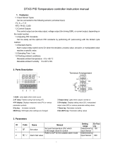
1.4.1 Z-TIO module
Module mainframe
<Terminal type>
* The 2-channel type does not have neither an input select switch (for CH3) and nor an input select switch (for CH4).
<Connector type>
** The 2-channel type does not have neither an input select switch (for CH3) and nor an input select switch (for CH4).
Indication lamps
FAIL/RUN [Green or Red] When normal (RUN): A green lamp is on
Self-diagnostic error (FAIL): A green lamp flashes
Instrument abnormality (FAIL): A red lamp is on
RX/TX [Green] During data send and receive: A green lamp turns on
Switches
Address setting switch Sets the Z-TIO module address.
(Refer to P. 5-2.)
DIP switch Sets the communication speed, data bit configuration, and communication
protocol. (Refer to P. 5-3.)
Input select switch Selector switch for the measured input type.
(Refer to P. 8-70.)
Input
select switch*
(for CH3)
Input
select switch*
(for CH4)
DIP switch
Input select
switch
(for CH1)
Input select
switch
(for CH2)
(Right side) (Left side)
CT1
CT2
LOADER
CT4
CT3
TIO
FAIL/ UNR
RX/TX
0
2
1
3
4
5
9
8
7
6
C
A
B
D
E
F
0
2
1
3
4
5
9
8
7
6
C
A
B
D
E
F
CT1
CT2
RNU/LIAF
RX/TX
TIO
(Z-TIO-AT: 4-channel type)
Loader communication
connector
Indication lamps
Address setting
switch
CT Input connector
(Optional)
Input/Output terminals
(Z-TIO-BT: 2-channel type)
CN1
CN3
CN2
CN4
0
2
1
3
4
5
9
8
7
6
C
A
B
D
E
F
CT1
CT2
CT3
CT4
TIO
FAIL/ UNR
RX/TX
LOADER
TIO
CN1
CN3
CN2
CN4
0
2
1
3
4
5
9
8
7
6
C
A
B
D
E
F
CT1
CT2
RNU/LIAF
RX/TX
LOADE R
Loader communication
connector
Indication lamps
Address setting
switch
CT Input connector
(Optional)
Input/Output connector
DIP switch
Input select
switch
(for CH1)
Input select
switch
(for CH2)
(Right side)
Input
select switch
**
(for CH3)
Input
select switch **
(for CH4)
(Left side)
(Z-TIO-BC: 2-channel type)(Z-TIO-AC: 4-channel type)

1. OUTLINE
IMS01T04-E6
1-10
Base
Mounting bracket
Used to fix the module on DIN rails and
also to fix each module joined together.
(Base: Rear)
Mounting holes (M3 screw)
Holes for screws to fix the base to
a panel, etc.
Customer must provide the M3 screws.
Power supply terminals
Supply power to only one of the joined
modules, and all of the joined modules will
receive power.
(Refer to 4.1 Wiring Cautions)
Used to mechanically and electrically connect
each module.
Joint connector
Communication terminals (RS-485)
Connect communication wires to only one o
f
the joined modules, and all of the joined
modules will communicate.
(Base: Front)
Base
(Right side)
(Z-TIO-A: Terminal type)
(Right side)
(Z-TIO-A: Connector type)
Base

1. OUTLINE
IMS01T04-E6
1-11
1.4.2 Z-DIO module
Module mainframe
Indication lamps
FAIL/RUN [Green or Red] When normal (RUN): A green lamp is on
Self-diagnostic error (FAIL): A green lamp flashes
Instrument abnormality (FAIL): A red lamp is on
RX/TX [Green] During data send and receive: A green lamp turns on
Switches
Address setting switch Sets the Z-DIO module address.
(Refer to P. 5-2.)
DIP switch Sets the communication speed, data bit configuration, and communication
protocol. (Refer to P. 5-3.)
Terminal configurations of the base are the same as the base of Z-TIO module. (Refer to P. 1-10)
DIP switch
LOADER
IN OUT
DIO
FAIL/ UNR
RX/TX
0
2
1
3
4
5
9
8
7
6
C
A
B
D
E
F
<Terminal type>
Digital input
terminals
Loader
communication
connector
Indication lamps
A
ddress setting switch
Base
Digital output
terminals
(Right side)
CN1
CN3
CN2
CN4
0
2
1
3
4
5
9
8
7
6
C
A
B
D
E
F
FAIL/ UNR
RX/TX
LOADER
IN OUT
DIO
DIP switch
Base
<Connector type>
Digital input
connector
Digital output
connector
Loader
communication
connector
Indication lamps
A
ddress setting switch
(Right side)

IMS01T04-E6
1-12
MEMO
/