Page is loading ...


DeZURIK
Instruction and Operating Manual Page 2 © 2022 DeZURIK, Inc.
Instructions
These instructions are for use by personnel who are responsible for the installation, operation and
maintenance of DeZURIK valves, actuators or accessories.
Safety Messages
All safety messages in the instructions are identified by a general warning sign and the signal word CAUTION,
WARNING or DANGER. These messages indicate procedures to avoid injury or death.
Safety label(s) on the product indicate hazards that can cause injury or death. If a safety label becomes difficult
to see or read, or if a label has been removed, please contact DeZURIK for replacement label(s).
Personnel involved in the installation or maintenance of valves should be constantly alert to potential
emission of pipeline material and take appropriate safety precautions. Always wear suitable protection
when dealing with hazardous pipeline materials. Handle valves which have been removed from service
with suitable protection for any potential pipeline material in the valve.
Inspection
Your DeZURIK product has been packaged to provide protection during shipment; however, items can be
damaged in transport. Carefully inspect the unit for damage upon arrival and file a claim with the carrier if
damage is apparent.
Parts
Replaceable wear parts are listed on the assembly drawing. These parts can be stocked to minimize
downtime. Order parts from your local DeZURIK sales representative or directly from DeZURIK. When ordering
parts please provide the following information:
If the valve has a data plate: please include the 7-digit part number with either 4-digit revision number
(example: 9999999R000) or 8-digit serial number (example: S1900001) whichever is applicable. The
data plate will be attached to the valve assembly. Also, include the part name, the assembly drawing
number, the balloon number and the quantity stated on the assembly drawing.
If there isn't any data plate visible on the valve: please include valve model number, part name, and
item number from the assembly drawing. You may contact your local DeZURIK Representative to help
you identify your valve.
DeZURIK Service
DeZURIK service personnel are available to maintain and repair all DeZURIK products. DeZURIK also offers
customized training programs and consultation services. For more information, contact your local DeZURIK
sales representative or visit our website at DeZURIK.com.

DeZURIK
APCO CDD-9000T Double Door Check Valves
September 2015 Page 3 D12041
Table of Contents
Description - - - - - - - - - - - - - - - - - - - - - - - - - - - - - - - - - - - - - - - - - - - - - - - - - - - - - 4
Handling and Storage - - - - - - - - - - - - - - - - - - - - - - - - - - - - - - - - - - - - - - - - - - - - - 4
Installation - - - - - - - - - - - - - - - - - - - - - - - - - - - - - - - - - - - - - - - - - - - - - - - - - - - - - 4
Fusion/Powder Coated Valves - - - - - - - - - - - - - - - - - - - - - - - - - - - - - - - - - - - - - - - 4
Maintenance - - - - - - - - - - - - - - - - - - - - - - - - - - - - - - - - - - - - - - - - - - - - - - - - - - - 5
Disassembly Procedure - - - - - - - - - - - - - - - - - - - - - - - - - - - - - - - - - - - - - - - - - -
5
Assembly Procedure - - - - - - - - - - - - - - - - - - - - - - - - - - - - - - - - - - - - - - - - - - - - 6
Operation - - - - - - - - - - - - - - - - - - - - - - - - - - - - - - - - - - - - - - - - - - - - - - - - - - - - - - 6
Drawings - - - - - - - - - - - - - - - - - - - - - - - - - - - - - - - - - - - - - - - - - - - - - - - - - - - - - - 7
Troubleshooting - - - - - - - - - - - - - - - - - - - - - - - - - - - - - - - - - - - - - - - - - - - - - - - - - 8

DeZURIK
APCO CDD-9000T Double Door Check Valves
D12041 Page 4 September 2015
Description
A Double Door Check Valve consists of a valve body, torsion spring loaded hinged doors, and a
resilient seat compression molded to valve body. The spring loaded doors move away from the valve
seat to allow flow in the forward direction, and return to valve seat when upstream flow is stopped.
Handling and Storage
Lifting the valve improperly may damage it. Do not fasten lifting devices through the seat opening in the
body. Lift the valve with slings, chains or cables fastened around the valve body, or fastened to bolts or
rods through bolt holes in the flanges.
If installation will be delayed, place valve indoors in secure, weather tight storage. If temporary outside
storage is unavoidable, make sure a vermin proof rain cover (water shedding tarp, etc.) is secured
around/over the equipment to keep off rain and mud. Skid and set the assembly on a flat, solid, and
well drained surface for protection from ground moisture, runoff and pooled rain water.
Installation
The APCO CDD-9000T Double Door Check Valve may be installed in a horizontal or vertical position
(with the flow upward). Valve supports are not needed. The Valve must be installed with the hinge
pin in the vertical position for horizontal flow applications.
• Before installation, remove foreign material such as weld spatter, oil, grease, and dirt from the
pipeline.
• Prepare pipe ends and install valves in accordance with the pipe manufacture’s instructions for
the joint used.
Do not deflect the pipe-valve joint. Minimize bending stresses in the valve end
connection with pipe loading.
If excessive seat leakage occurs during start-up, recheck the installation and
eliminate any distortion to the valve body.
• Ensure the valve and pipeline flanges are concentric to ensure proper flange sealing and seat
leakage control.
• Tighten the flange bolts or studs in a crisscross pattern and minimum of four stages.
Fusion/Powder Coated Valves
Valves with fusion/powder coated exterior paint require flat washers to be installed
under the flange nuts when installing the valve to the pipeline flange to prevent the
paint from cracking or chipping.

DeZURIK
APCO CDD-9000T Double Door Check Valves
September 2015 Page 5 D12041
Maintenance
It is suggested that these valves, which do not require routine scheduled maintenance, be included as
part of the normal facility equipment inspections for any malfunction while under normal usage
conditions. A malfunction of the valve will be apparent by the leakage of the media. In some
installations where there is a high head, a moderate “slam” of the Double Doors will be normal.
.
These valves may open or close without warning due to flow changes from pumps starting
and stopping. Servicing these valves while the pipeline is under pressure can cause
personal injury or equipment damage.
Relieve pipeline pressure and lockout the pumps before servicing the valve.
Disassembly Procedure
See Figure 1 for part identification.
Instructions for valves using pin retainers
1. Relieve the pressure in the pipeline.
2. Remove valve from line.
3. Remove pin retainers (7).
4. Remove stop pin (6) from body (1).
5. Depress spring or springs (4) to free hinge pin (5) and push hinge pin out of the body (1) while
holding the spring firmly, since it is preloaded and may snap out.
6. Remove spring or springs (4), doors (2).
Instructions for valves using caps
1. Relieve the pressure in the pipeline.
2. Remove valve from line.
3. Loosen cap (9) set screws.
4. Pinch caps (9) inward and withdraw caps, hinge pin (5) and stop pin (6), spring (4), and doors
(2).

DeZURIK
APCO CDD-9000T Double Door Check Valves
D12041 Page 6 September 2015
Assembly Procedure
See Figure 1 for part identification.
Instructions for valves using pin retainers
1. Clean all ports with a suitable solvent. Trichloroethylene is recommended, particularly for
resilient seated valves.
2. Position doors (2) in body (1), aligning pin holes in the doors with holes in the body.
3. Partially install hinge pin (5). Lateral movement of doors after assembly should not exceed
3/32” in sizes 2 - 12” (50 – 300 mm) and 5/32” for sizes 14” (350 mm) and above.
4. Wind up spring or springs (4) one-half turn to obtain initial torsion and install spring with the
spring arms flat on the doors (2). Do not unwind spring as this will change spring torque and
also limit the opening of the doors. Complete insertion of hinge pin (5).
5. Install stop pin (6) into body (1).
6. Install pin retainers (7) using suitable thread sealant to insure a positive seal.
Instructions for valves using caps
1. Clean all ports with a suitable solvent. Trichloroethylene is recommended, particularly for
resilient seated valves.
2. Position doors (2) together so pin holes in doors are aligned.
3. Slide hinge pin (5) through first pair of door pin holes.
4. Wind up spring or springs (4) one-half turn to obtain initial torsion and install spring with the
spring arms flat on the doors (2). Do not unwind spring as this will change spring torque and
also limit the opening of the doors.
5. Slide hinge pin (5) fully through spring (4) and second pair of door (2) pin holes.
6. Position hinge pin (5) in holes of upper and lower caps (9) at end farthest from end cap flange.
7. Position stop pin in holes of upper and lower caps (9) closest to end cap flange.
8. Position caps (9) next to upper and lower cap grooves in valve body (1) and slide doors (2),
spring (4), pins (5 and 6) and caps (9) fully into place in valve body (1).
9. Tighten caps set screws.
Operation
The Double Door Check Valve is held closed by the legs of a torsion spring. Flow from the pump
causes the Double Door Check Valve to open. Conversely, when the pump is stopped, flow decay
occurs and at a point near zero velocity, the force from the legs of the torsion spring instantly closes the
Double Door Check valve for non-slam shut-off.

DeZURIK
APCO CDD-9000T Double Door Check Valves
September 2015 Page 7 D12041
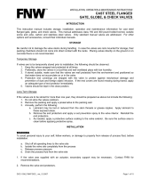
Drawings
* Lifting Eye Bolt is used on
10” and larger Ductile Iron
valves, and on 8” and larger
Carbon Steel and Stainless
Steel valves.
NO
DESCRIPTION
1
Body
2
Door
3
Seat
4
Spring
5
Hinge Pin
6
Stop Pin
7
Pin Retainer (NPT
Plug)
8
Lifting Eye Bolt*
9
Cap
Figure 1 – CDD-9000T Double Door Check Valve (Wafer and Lugged versions)

DeZURIK
APCO CDD-9000T Double Door Check Valves
D12041 Page 8 September 2015
Troubleshooting
Condition Possible Cause Corrective Action
Valve leaks excessively from
one side of the doors to the
other.
Obstruction caught between
doors and seat. Remove obstruction.
Seat is worn or damaged. Repair or replace seat.
Valve slams Springs may be broken. Replace springs.
Valve won’t open Improper installation. Flow arrow on valve body should
be pointing in direction of flow.
Valve leaks at flange joint.
Loose flange bolting. Tighten flange bolting.
Blown flange gasket. Replace flange gasket.
Misalignment or damage to field
piping and supports. Adjust misalignment or repair
piping or supports.
Damaged flange face(s) or
improper flange connections.
Repair flange, replace valve
body or adjust flange
connections.

Limited Warranty
DeZURIK, Inc. (“Seller”) manufactured products, auxiliaries and parts thereof that we manufacture for a period of twenty-four (24) months from date
of shipment from Seller’s factory, are warranted to the original purchaser only against defective workmanship and material, but only if properly stored,
installed, operated, and serviced in accordance with Seller’s recommendations and instructions.
For items proven to be defective within the warranty period, your exclusive remedy under this limited warranty is repair or replacement of the defective
item, at Seller’s option, FCA Incoterms 2020 Seller’s facility with removal, transportation, and installation at your cost.
Products or parts manufactured by others but furnished by Seller are not covered by this limited warranty. Seller may provide repair or replacement
for other’s products or parts only to the extent provided in and honored by the original manufacturer’s warranty to Seller, in each case subject to the
limitations contained in the original manufacturer’s warranty.
No claim for transportation, labor, or special or consequential damages or any other loss, cost or damage is being provided in this limited warranty.
You shall be solely responsible for determining suitability for use and in no event shall Seller be liable in this respect.
This limited warranty does not warrant that any Seller product or part is resistant to corrosion, erosion, abrasion or other sources of failure, nor does
Seller warrant a minimum length of service.
Your failure to give written notice to us of any alleged defect under this warranty within twenty (20) days of its discovery, or attempts by someone other
than Seller or its authorized representatives to remedy the alleged defects therein, or failure to return product or parts for repair or replacement as
herein provided, or failure to store, install, or operate said products and parts according to the recommendations and instructions furnished by Seller
shall be a waiver by you of all rights under this limited warranty.
This limited warranty is voided by any misuse, modification, abuse or alteration of Seller’s product or part, accident, fire, flood or other Act of God, or
your failure to pay entire contract price when due.
The foregoing limited warranty shall be null and void if, after shipment from our factory, the item is modified in any way or a component of another
manufacturer, such as but not limited to; an actuator is attached to the item by anyone other than a Seller factory authorized service personnel.
All orders accepted shall be deemed accepted subject to this limited warranty, which shall be exclusive of any other or previous warranty, and this
shall be the only effective guarantee or warranty binding on Seller, despite anything to the contrary contained in the purchase order or represented by
any agent or employee of Seller in writing or otherwise, notwithstanding, including but not limited to implied warranties.
THE FOREGOING REPAIR AND REPLACEMENT LIMITED WARRANTY IS IN LIEU OF ALL OTHER WARRANTIES, OBLIGATIONS AND
LIABILITIES, INCLUDING, BUT NOT LIMITED TO, ALL WARRANTIES OF FITNESS FOR A PARTICULAR PURPOSE OR OF MERCHANTABILITY
OR OTHERWISE, EXPRESSED OR IMPLIED IN FACT OR BY LAW, AND STATE SELLER’S ENTIRE AND EXCLUSIVE LIABILITY AND YOUR
EXCLUSIVE REMEDY FOR ANY CLAIM IN CONNECTION WITH THE SALE AND FURNISHING OF SERVICES, GOODS OR PARTS, THEIR
DESIGN, SUITABILITY FOR USE, INSTALLATION OR OPERATIONS. NEITHER ANY PERFORMANCE OR OTHER CONDUCT, NOR ANY ORAL
OR WRITTEN INFORMATION, STATEMENT, OR ADVICE PREPARED BY SELLER OR ANY OF OUR EMPLOYEES OR AGENTS WILL CREATE A
WARRANTY, OR IN ANY WAY INCREASE THE SCOPE OR DURATION OF THE LIMITED WARRANTY.
Disclaimer
Metric fasteners should not be used with ASME Class 150/300 bolt holes and flange bolt patterns. If you use metric fasteners with ASME Class 150/300
bolt holes and flange bolt patterns, it may lead to product failure, injury, and loss of life. DeZURIK Inc. disclaims all liability associated with the use of
metric fasteners with ASME Class 150/300 bolt holes and flange patterns, including but not limited to personal injury, loss of life, loss of product,
production time, equipment, property damage, lost profits, consequential damages of any kind and environment damage and/or cleanup. Use of metric
fasteners with ASME Class 150/300 bolt holes and flange bolt patterns is a misuse that voids all warranties and contractual assurances. If you use
metric fasteners with ASME Class 150/300 bolt holes and flange bolt patterns, you do so at your sole risk and any liability associated with such use shall
not be the responsibility of DeZURIK, Inc. In addition to the foregoing, DeZURIK’s Manufacturer’s Conditions apply.
Limitation of Liability
IN NO EVENT SHALL SELLER BE LIABLE FOR ANY DIRECT, INDIRECT, SPECIAL, PUNITIVE, EXEMPLARY, OR CONSEQUENTIAL DAMAGES
(INCLUDING, BUT NOT LIMITED TO; DAMAGE TO OR LOSS OF OTHER PROPERTY OR EQUIPMENT, BUSINESS INTERUPTION, COST OF
SUBSTITUTE PRODUCTS, LOSS OF TIME, LOSS OF PROFITS OR REVENUE, COST OF CAPTIAL, LOSS OF USE, OR DIMINUTION IN VALUE)
WHATSOEVER, AND SELLER’S LIABILITY, UNDER NO CIRCUMSTANCES, WILL EXCEED THE CONTRACT PRICE FOR THE GOODS AND/OR
SERVICES FOR WHICH LIABILITY IS CLAIMED. ANY ACTION FOR BREACH OF CONTRACT BY YOU, OTHER THAN RIGHTS RESPECTING OUR
LIMITED WARRANTY DESCRIBED ABOVE, MUST BE COMMENCED WITHIN 12 MONTHS AFTER THE DATE OF SALE.
Sales and Service
For information about our worldwide locations, approvals, certifications and local representative:
Web site: www.dezurik.com E-Mail: info@dezurik.com
250 Riverside Ave. N., Sartell, MN 56377 ● Phone: 320-259-2000 ● Fax: 320-259-2227
DeZURIK, Inc. reserves the right to incorporate our latest design and material changes without notice or obligation.
Design features, materials of construction and dimensional data, as described in this manual, are provided for your information only
and should not be relied upon unless confirmed in writing by DeZURIK, Inc. Certified drawings are available upon request.
December 2022
/