
INSTRUCTION MANUAL
iE2820
DUAL BAND FM TRANSCEIVER
This device complies with Part 15 of the FCC Rules. Operation is sub-
ject to the following two conditions: (1) this device may not cause
harmful interference, and (2) this device must accept any interference
received, including interference that may cause undesired operation.

i
FOREWORD
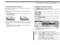
Thank you for purchasing this Icom product. The IC-E2820
DUAL BAND FM TRANSCEIVER
is designed and built with Icom’s
superior technology and craftsmanship. With proper care, this
product should provide you with years of trouble-free opera-
tion.
We want to take a couple of moments of your time to thank
you for making your IC-E2820 your radio of choice, and hope
you agree with Icom’s philosophy of “technology first.” Many
hours of research and development went into the design of
your IC-E2820.
DD
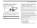
FEATURES
❍Diversity reception
❍DV (Digital Voice) with GPS operation
capabilities (Optional UT-123 is required)
❍V/V, U/U simultaneous receive capability
❍Independent controls for both left and right
receivers
❍Separate controller for flexible installation
❍Remote control microphone included
IMPORTANT
READ ALL INSTRUCTIONS carefully and completely
before using the transceiver.
SAVE THIS INSTRUCTION MANUAL— This in-
struction manual contains important operating instructions for
the IC-E2820.
EXPLICIT DEFINITIONS
WORD DEFINITION
RWARNING!
CAUTION
NOTE
Personal injury, fire hazard or electric shock
may occur.
Equipment damage may occur.
Recommended for optimum use. No risk of
personal injury, fire or electric shock.
Icom, Icom Inc. and the logo are registered trademarks of Icom
Incorporated (Japan) in the United States, the United Kingdom, Ger-
many, France, Spain, Russia and/or other countries.
All other products or brands are registered trademarks or trademarks
of their respective holders.

RWARNING RF EXPOSURE! This device emits Radio
Frequency (RF) energy. Extreme caution should be observed when
operating this device. If you have any questions regarding RF expo-
sure and safety standards please refer to the Federal Communica-
tions Commission Office of Engineering and Technology’s report on
Evaluating Compliance with FCC Guidelines for Human Radio fre-
quency Electromagnetic Fields (OET Bulletin 65).
RWARNING! NEVER connect the transceiver to an AC out-
let. This may pose a fire hazard or result in an electric shock.
RWARNING! NEVER operate the transceiver while driving a
vehicle. Safe driving requires your full attention—anything less may
result in an accident.
NEVER connect the transceiver to a power source of more than
16 V DC. This will damage the transceiver.
NEVER connect the transceiver to a power source using reverse
polarity. This will damage the transceiver.
NEVER cut the DC power cable between the DC plug and fuse
holder. If an incorrect connection is made after cutting, the transceiver
may be damaged.
NEVER expose the transceiver to rain, snow or any liquids. The
transceiver may be damaged.
NEVERoperate or touch the transceiver with wet hands. This may
result in an electric shock or damage the transceiver.
NEVERplace the transceiver where normal operation of the vehi-
cle may be hindered or where it could cause bodily injury.
NEVER let objects impede the operation of the cooling fan on the
rear panel.
DO NOT push the PTT when not actually desiring to transmit.
DO NOT allow children to play with any radio equipment contain-
ing a transmitter.
During mobile operation, DO NOT operate the transceiver with-
out running the vehicle’s engine. When the transceiver’s power is ON
and your vehicle’s engine is OFF, the vehicle’s battery will soon be-
come exhausted.
AVOID using or placing the transceiver in direct sunlight or in
areas with temperatures below –10°C or above +60°C.
BE CAREFUL! The transceiver will become hot when operat-
ing it continuously for long periods.
AVOID setting the transceiver in a place without adequate venti-
lation. Heat dissipation may be affected, and the transceiver may be
damaged.
AVOID the use of chemical agents such as benzine or alcohol
when cleaning, as they can damage the transceiver’s surfaces.
USE Icom microphones only (supplied or optional). Other manu-
facturer’s microphones have different pin assignments and may dam-
age the transceiver if attached.
ii
PRECAUTIONS

iii
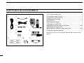
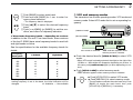
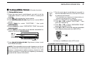
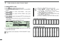
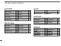
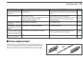
qDC power cable (3 m) ………………………………………1
wController cable (10 cm†) ……………………………………1
eSeparation cable (3.4 m†) …………………………………1
rMagnets with screws ………………………………………2
tFuse (20 A) …………………………………………………1
yMicrophone hanger …………………………………………1
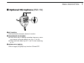
uMicrophone (HM-133)* ……………………………………1
iMounting screws, nuts and washers …………………1 set
oMobile mounting bracket …………………………………1
!0Microphone connector plate with screw ……………1 set
!1Remote controller bracket …………………………………1
*HM-154
HAND MICROPHONE
may be supplied with some versions.
†Approx.
qw
e
r
t
y
u
o
i
!1!0
SUPPLIED ACCESSORIES

iv
TABLE OF CONTENTS 1
2
3
4
5
6
7
8
9
10
11
12
13
14
15
16
17
18
19
FOREWORD .................................................................................... i
IMPORTANT .................................................................................... i
EXPLICIT DEFINITIONS .................................................................. i
PRECAUTIONS ............................................................................... ii
SUPPLIED ACCESSORIES ........................................................... iii
TABLE OF CONTENTS .................................................................. iv
QUICK REFERENCE GUIDE .................................................. I–XIV
■Installation ................................................................................ I
■Your first contact ..................................................................... X
■Repeater operation ............................................................... XII
■Programming memory channels........................................... XIII
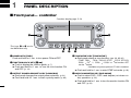
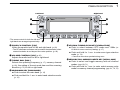
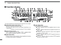
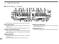
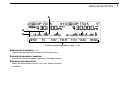
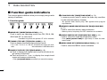
1PANEL DESCRIPTION ........................................................ 1–14
■Front panel— controller .......................................................... 1
■Function display ...................................................................... 3
■Function guide indications ...................................................... 7
■Main unit ................................................................................. 9
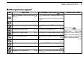
■Microphone (HM-133) ........................................................... 11
■Microphone keypad ............................................................... 12
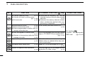
■Optional microphones (HM-154)............................................ 14
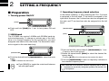
2SETTING A FREQUENCY ................................................. 15–19
■Preparation ........................................................................... 15
■Using the tuning dial ............................................................. 17
■Using the [Y]/[Z] keys .......................................................... 17
■Using the keypad .................................................................. 17
■Tuning step selection ............................................................ 18
■Lock functions ....................................................................... 19
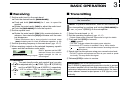
3BASIC OPERATION .......................................................... 20–28
■Receiving .............................................................................. 20
■Transmitting .......................................................................... 20
■Selecting output power ......................................................... 21
■Operating mode selection ..................................................... 21
■Squelch attenuator ................................................................ 22
■V/V, U/U simultaneous receive (Para-watch) ........................ 23
■Sub-band mute/busy beep .................................................... 24
■Monitor function .................................................................... 24
■Single band operation ........................................................... 25
■One-touch PTT function ........................................................ 26
■Audio mute function .............................................................. 27
■Band scope ........................................................................... 27
4REPEATER OPERATION .................................................. 29–34
■General ................................................................................. 29
■Accessing a repeater ............................................................ 30
■Subaudible tones .................................................................. 32
■Offset frequency .................................................................... 34
5DV MODE OPERATION (Optional UT-123 is required) ..... 35–59
■Digital mode operation .......................................................... 35
■Call sign programming .......................................................... 35
■Digital voice mode operation ................................................. 38
■DV automatic detect ............................................................. 40
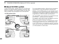
■About D-STAR system .......................................................... 41
■Digital repeater operation ...................................................... 42
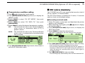
■Received call sign ................................................................. 47
■Copying the call sign ............................................................. 49

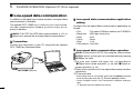
■Break-in communication ....................................................... 51
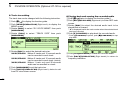
■Message operation ............................................................... 52
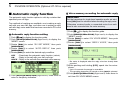
■Automatic reply function ........................................................ 55
■EMR communication ............................................................. 56
■Low-speed data communication ........................................... 57
■DV voice memory .................................................................. 58
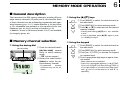
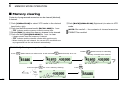
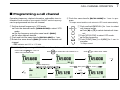
6MEMORY MODE OPERATION .......................................... 60–70
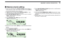
■General description ............................................................... 60
■Memory channel selection .................................................... 60
■Programming a memory channel .......................................... 61
■Memory bank selection ......................................................... 63
■Memory bank setting ............................................................. 64
■Programming memory/bank/scan name ............................... 65
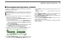
■Copying memory contents .................................................... 67
■Memory clearing ................................................................... 69
■Erasing/transferring bank contents ....................................... 70
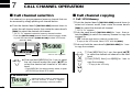
7CALL CHANNEL OPERATION ......................................... 71–72
■Call channel selection ........................................................... 71
■Call channel copying ............................................................. 71
■Programming a call channel ................................................. 72
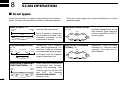
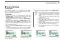
8SCAN OPERATION ........................................................... 73–78
■Scan types ............................................................................ 73
■Scan start/stop ...................................................................... 74
■Scan edges programming ..................................................... 75
■Scan resume condition ......................................................... 77
■Skip channel setting .............................................................. 78
9 PRIORITY WATCH ............................................................. 79–80
■Priority watch types ............................................................... 79
■Priority watch operation ........................................................ 80
10DTMF MEMORY ENCODER .............................................. 81–84
■Programming a DTMF tone sequence .................................. 81
■Transmitting a DTMF tone sequence .................................... 82
■DTMF speed ......................................................................... 84
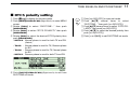
11 TONE SQUELCH AND POCKET BEEP ............................ 85–90
■Tone/DTCS squelch beep operation ..................................... 85
■DTCS polarity setting ............................................................ 88
■Tone scan .............................................................................. 89
■Digital call sign/digital code squelch ..................................... 90
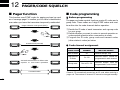
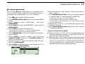
12PAGER/CODE SQUELCH ................................................. 91–94
■Pager function ....................................................................... 91
■Code programming ............................................................... 91
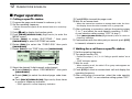
■Pager operation .................................................................... 93
■Code squelch ........................................................................ 94
v
TABLE OF CONTENTS

vi
13MENU SCREEN OPERATION ......................................... 95–112
■General ................................................................................. 95
■Menu list ................................................................................ 96
■Item list .................................................................................. 96
■SET MODE items .................................................................. 99
■DV SET MODE items .......................................................... 101
■SCAN items ........................................................................ 103
■DUP/TONE items................................................................. 104
■DISPLAY items ................................................................... 105
■SOUND items ..................................................................... 107
■DV GPS items ..................................................................... 108
■PACKET items .................................................................... 109
■GPS SET MODE items ....................................................... 109
■GPS-A SET MODE items .................................................... 111
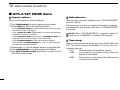
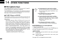
14OTHER FUNCTIONS ..................................................... 113–120
■Microphone keys ................................................................. 113
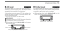
■All reset ............................................................................... 114
■Partial reset ......................................................................... 114
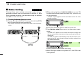
■Data cloning ........................................................................ 115
■Auto power OFF .................................................................. 116
■Time-out timer ..................................................................... 116
■Packet operation ................................................................. 117
15GPS/GPS-A OPERATION .............................................. 121–128
■GPS operation .................................................................... 121
■GPS-A operation ................................................................. 128
16MAINTENANCE ............................................................. 129–131
■Troubleshooting .................................................................. 129
■Fuse replacement ............................................................... 130
■Optional UT-123 installation ................................................ 131
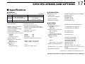
17SPECIFICATIONS AND OPTIONS ................................ 132–134
■Specifications ...................................................................... 132
■Options ................................................................................ 133
18ABOUT CE ..................................................................... 135–136
1
2
3
4
5
6
7
8
9
10
11
12
13
14
15
16
17
18
19

I
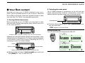
QUICK REFERENCE GUIDE
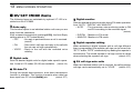
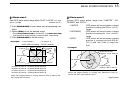
■Installation
DPrecaution— magnets
RCAUTION
Magnets are used for the controller’s attachment to the main
unit.
NEVER hold the whole unit by the controller only when carry-
ing the transceiver. Carry the transceiver holding the main
unit. If held by the controller, the main unit may drop off and
may result in injury to the person carrying it or damage the
transceiver.
NEVER attach the controller on the main unit’s top cover, par-
ticularly around the internal speaker grill. It may cause the
contents of the CPU and memory device could be deleted.
may cause the contents of the CPU and memory device
could be deleted.
NEVER put the controller near a clock, television set (CRT
type), magnetic compass and any magnetic/IC cards, credit
cards, etc. It may cause the product to malfunction, and the
content of the magnetic card could be deleted.
Please note that the controller may drop off when a high im-
pact or vibration is applied.
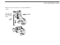
DInstallation methods
•The supplied remote controller bracket and separation cable
can be used for installation.
•The optional MB-65
MOUNTING BASE
must be used when in-
stalling into your vehicle.
•Optional OPC-440
MICROPHONE CABLE
(5.0 m) is available
to extend the microphone cable.
•Optional OPC-441
SPEAKER CABLE
(5.0 m) is available to ex-
tend the speaker cable.
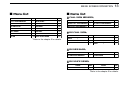
Main unit
Controller

II
QUICK REFERENCE GUIDE
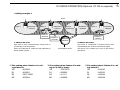
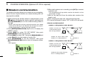
DLocation
Select a location which can support the weight of the trans-
ceiver and does not interfere with driving. We recommend the
locations shown in the diagram below.
NEVER place the transceiver or remote controller where nor-
mal operation of the vehicle may be hindered or where it
could cause bodily injury.
NEVER place the transceiver or remote controller where air
bag deployment may be obstructed.
DO NOT place the transceiver or remote controller where hot
or cold air blows directly onto it.
AVOID placing the transceiver or remote controller in direct
sunlight.
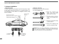
DUsing the mounting bracket
qDrill 4 holes where the mounting bracket is to be installed.
•Approx. 5.5–6 mm when using nuts; approx. 2–3 mm when using
self-tapping screws.
wInsert the supplied screws, nuts and washers through the
mounting bracket and tighten.
eAdjust the angle for your suitable position.
IMPORTANT!
Detailed installation notes for Icom mobile transceivers to
fitted into vehicles are available. Contact your Icom dealer
or distributor.
Nut
Spring washer
When using
self-tapping
screws
Flat washer Mounting nut
Mounting
bracket
25˚
Controller Main unit
Main unit
Main unit
Quick reference guide

III
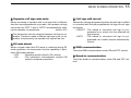
QUICK REFERENCE GUIDE
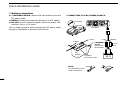
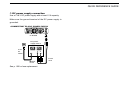
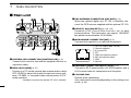
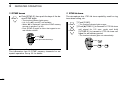
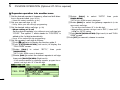
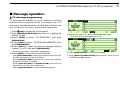
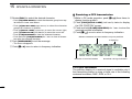
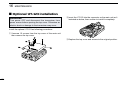
DController/Separation cable connection
Two connection cables, controller cable (10 cm) for single
body installation and separation cable (3.4 m) for remote in-
stallation, are supplied with the IC-E2820.
Connect the controller and the main unit using with the sup-
plied connection cable as follows.
IMPORTANT!— number of pin
The connectors on the ends of the connection cable have dif-
ferent numbers of pins - one end has 6 pins and the other end
4 pins. You should connect the 6-pin connector to the main
unit, and the 4-pin connector to the controller.
DMicrophone connection
Amicrophone connector is available on the main unit front
panel. Connect the supplied microphone connector as illus-
trated below.
Attach the supplied microphone connector plate after the mi-
crophone connection, otherwise the controller will separate
from the mail unit when the microphone cable is pulled during
single body installation.
Controller Microphone
Main unit
Controller Main unit
4-pin connector 6-pin connector

IV
QUICK REFERENCE GUIDE
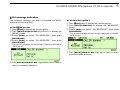
DOptional GPS antenna connection
When the optional UT-123 is installed, the GPS antenna sup-
plied with the UT-123 can be connected.
Connect the GPS antenna as below.
Mount the GPS antenna onto a convenient flat surface. The
GPS antenna includes magnet mount base, therefore, the an-
tenna can be mounted onto a metal roof/wall, etc.
NOTE
When the GPS antenna is connected, only remote installa-
tion is allowed.
DImportant notes when using GPS receiver
• The GPS antenna is not weather-proof construction, there-
fore, NEVER install the antenna in outdoor.
• Please do not install the GPS antenna close the TX an-
tenna. The transmit signal may cause GPS receiver mul-
function.
• The GPS signal cannot pass through the metal object.
When installing GPS antenna inside a vehicle, we recom-
mend to mount under the front or rear glass such as on the
dashboard, etc. Please avoid the areas shown in the follow-
ing:
1. Do not mount where it will block the driver’s view.
2. Do not mount where the air bags could deploy.
• The Global Positioning System (GPS) is built and operated
by the US Defence Department. The Department is respon-
sible for accuracy and maintenance of the system. Any
changes that the Department makes may affect the accu-
racy and function of the GPS system.
• When GPS receiver is activated, please do not cover the
GPS antenna with any object.
• The GPS receiver may not work if used in the following lo-
cations:
1. Tunnels or high-rise buldings
2. Underground parking lot
3. Under a bridge or viaduct
4. In remote forested areas
5. Under bad weather condition (rainy or cloudy day)
to [GPS ANT]
GPS antenna
GPS antenna cable length: approx. 5 m (16.4 ft)
Quick reference guide

V
QUICK REFERENCE GUIDE
DController’s attachment
You can attach the controller of the IC-E2820 by one of 2
methods.
•Example 1
•Example 2
DRemote installation
The supplied remote controller bracket is used for remote in-
stallation.
• Attach the remote controller
bracket onto a flat surface
using with 4 self-tapping
screws (2.6 mm(d)), or double-
sticky tape, etc., as at left,
then attach remote controller
to the bracket.
When installing into your vehicle
qAttach the supplied remote controller bracket as below.
Remote controller
bracket Remote
controller
These screws
are not supplied.
Remote controller bracket

VI
QUICK REFERENCE GUIDE
Quick reference guide
wAttach the remote controller on to the optional MB-65 as
below.
Remote controller
bracket
Optional
MB-65
Adjust the view-
ing angle for
maximum visibili-
ty of the function
display.

VII
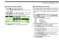
DBattery connection
➥RWARNING NEVER remove the fuse holders from the
DC power cable.
➥NEVER connect the transceiver directly to a 24 V battery.
➥DO NOT use the cigarette lighter socket for power con-
nections. (See p. 10 for details)
Use a rubber grommet when passing the DC power cable
through a metal plate to prevent a short circuit.
•CONNECTING TO A DC POWER SOURCE
IC-E2820
Fuses
20 A
black
red⊕−
12 V
Grommet
NOTE:
Use terminals for the
cable connections.
R
WARNING
!
NEVER
remove the
fuse holders.
Crimp Solder
12 V
battery Supplied
DC power cable
+ red
_ black
QUICK REFERENCE GUIDE

VIII
QUICK REFERENCE GUIDE
DDC power supply connection
Use a 13.8 V DC power supply with at least 15 A capacity.
Make sure the ground terminal of the DC power supply is
grounded.
•CONNECTING TO A DC POWER SUPPLY
See p. 130 for fuse replacement.
DC power
supply 13.8 V
to an
AC
outlet
Fuses
20 A
black
red⊕
−
⊕
−
IC-E2820
Quick reference guide

IX
QUICK REFERENCE GUIDE
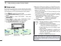
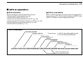
DAntenna installation
•Antenna location
To obtain maximum performance from the transceiver, select
a high-quality antenna and mount it in a good location. It is
not necessary to use radials on a magnetic mount (“mag
mount”) antenna.
•Antenna connector
The antenna uses a PL-259 connector.
•PL-259 CONNECTOR
qSlide the coupling ring
down. Strip the cable
jacket and soft solder.
wStrip the cable as shown
at left. Tin the center con-
ductor.
eSlide the connector body
on and solder it.
rScrew the coupling ring
onto the connector body.
NOTE: There are many publications covering proper an-
tennas and their installation. Check with your local dealer
for more information and recommendations.
30 mm
10 mm (soft solder)
10 mm
1–2 mm
solder solder
Soft
solder
Coupling ring
To antenna
for diversity
reception
To antenna
for Tx/Rx
Roof-mount antenna
(Drill a hole or use a magnetic mount.)
Gutter-mount antenna
Trunk-mount
antenna

X
QUICK REFERENCE GUIDE
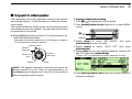
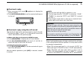
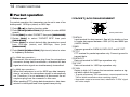
■Your first contact
Now that you have your IC-E2820 installed in your car or
shack, you are probably anxious to get on the air. We would
like to take you through a few basic operation steps to make
your first time “On The Air” an enjoyable experience.
1. Turning ON the transceiver
Before powering up your IC-E2820, you may want to make
sure the audio volume and squelch level controls are set in
9–10 o’clock positions.
Although you have purchased a brand new transceiver, some
settings may be changed from the factory defaults because
of the Quality Control (QC) process. Resetting the CPU is
necessary to start from factory default.
➥While pushing both band’s [M/CALL•MW] keys, push and
hold [PWR] for 1 sec. to reset the CPU.
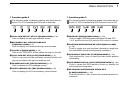
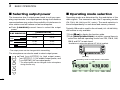
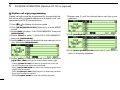
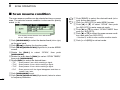
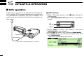
2. Selecting the main band
The IC-E2820 displays 2 frequencies on the left and right
bands simultaneously. However, transmission, some keys
and microphone operation apply only to the main band.
➥Push the desired band’s (left or right) [MAIN•BAND] to se-
lect the main band.
•“Q” appears for the main band.
Using the HM-133
You can select the main band from the HM-133.
Push
Push again
[MAIN•BAND]
[M/CALL•MW]
While pushing both [M/CALL•MW], turn power ON.
[M/CALL•MW]
[PWR]
Set both [VOL] and [SQL] controls to 9–10 o’clock positions.
Quick reference guide

XI
QUICK REFERENCE GUIDE
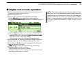
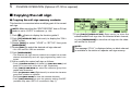
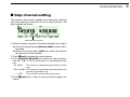
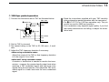
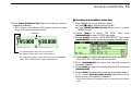
3. Selecting the operating frequency band
The IC-E2820 can use 2 m or 70 cm on either the left or right
band. The operating band can be exchanged between them,
and using the same bands, V/V and U/U, is also possible..
➥Push and hold the desired band’s (left or right)
[MAIN•BAND] for 1 sec. then rotate the appropriate band’s
[DIAL].
•Push [MAIN•BAND] momentarily to return to frequency indica-
tion.
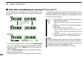
4. Tune the frequency
The tuning dial will allow you to dial in the frequency you want
to use. Pages 17 and 18 will instruct you on how to set the
tuning speed.
Using the HM-133
You can directly enter the frequency with the HM-133 keypad
for the main band.
[EXAMPLE]: Setting frequency to 145.3625 MHz.
Push
Push
Push
Push
Rotate the desired [DIAL].
[DIAL]
[MAIN•BAND]
Frequency band initial is displayed.

XII
QUICK REFERENCE GUIDE
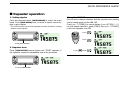
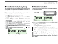
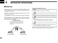
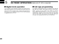
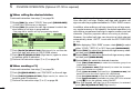
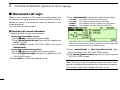
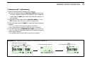
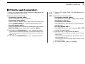
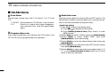
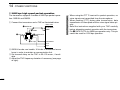
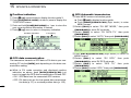
■Repeater operation
1. Setting duplex
Push the desired band’s [MAIN•BAND] to select the main
band. Push [DUP•MONI] once or twice to select minus du-
plex or plus duplex.
•The USA version has an auto repeater function, therefore, setting
duplex is not required.
2. Repeater tone
Push [TONE•DTMF] several times until “TONE” appears, if
the repeater requires a subaudible tone to be accessed.
Using the HM-133
Plus or minus duplex selection and the repeater tone setting
can be made easily via the HM-133.
Push [
DUP
–7(TONE)] for minus duplex; [
DUP
+8(TSQLS)]
for plus duplex selection, push [FUNC] then [
DUP
–7(TONE)]
to turn the repeater tone ON.
Push
Push , then
Push
Push [TONE•DTMF].
Push [DUP•MONI].
Quick reference guide

XIII
QUICK REFERENCE GUIDE
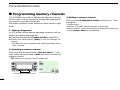
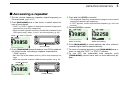
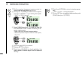
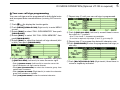
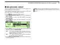
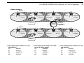
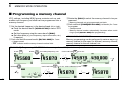
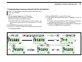
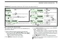
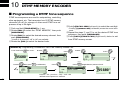
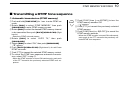
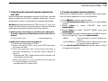
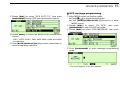
■Programming memory channels
The IC-E2820 has a total of 522 memory channels (including
20 scan edges and 2 call channels) for storing often used operat-
ing frequency, repeater settings, etc.
Any memory channel can be recalled on either the left or right
band.
1. Setting a frequency
In VFO mode, set the desired operating frequency with re-
peater, tone and tuning steps, etc.
➥Push the desired band’s [V/MHz•SCAN] to select VFO.
➥
Rotate the same band’s [DIAL] to set the desired fre-
quency.
•Set other data, such as repeater tone, duplex information, tuning
step), if desired.
2. Selecting a memory channel
Push and hold the same band’s [M/CALL•MW] for 1 sec.,
then rotate the same band’s [DIAL] to select the desired
memory channel.
•“X” indicator and memory channel number blink.
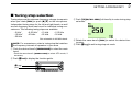
3. Writing a memory channel
Push and hold [S.MW](M/CALL•MW) (Left band’s) for 1 sec.
to program.
•3 beeps sound
•Return to VFO mode automatically after programming.
•Memory channel number automatically increases when continuing
to push [M/CALL•MW] after programming.
Push [M/CALL•MW] for 1 sec.
Page is loading ...
Page is loading ...
Page is loading ...
Page is loading ...
Page is loading ...
Page is loading ...
Page is loading ...
Page is loading ...
Page is loading ...
Page is loading ...
Page is loading ...
Page is loading ...
Page is loading ...
Page is loading ...
Page is loading ...
Page is loading ...
Page is loading ...
Page is loading ...
Page is loading ...
Page is loading ...
Page is loading ...
Page is loading ...
Page is loading ...
Page is loading ...
Page is loading ...
Page is loading ...
Page is loading ...
Page is loading ...
Page is loading ...
Page is loading ...
Page is loading ...
Page is loading ...
Page is loading ...
Page is loading ...
Page is loading ...
Page is loading ...
Page is loading ...
Page is loading ...
Page is loading ...
Page is loading ...
Page is loading ...
Page is loading ...
Page is loading ...
Page is loading ...
Page is loading ...
Page is loading ...
Page is loading ...
Page is loading ...
Page is loading ...
Page is loading ...
Page is loading ...
Page is loading ...
Page is loading ...
Page is loading ...
Page is loading ...
Page is loading ...
Page is loading ...
Page is loading ...
Page is loading ...
Page is loading ...
Page is loading ...
Page is loading ...
Page is loading ...
Page is loading ...
Page is loading ...
Page is loading ...
Page is loading ...
Page is loading ...
Page is loading ...
Page is loading ...
Page is loading ...
Page is loading ...
Page is loading ...
Page is loading ...
Page is loading ...
Page is loading ...
Page is loading ...
Page is loading ...
Page is loading ...
Page is loading ...
Page is loading ...
Page is loading ...
Page is loading ...
Page is loading ...
Page is loading ...
Page is loading ...
Page is loading ...
Page is loading ...
Page is loading ...
Page is loading ...
Page is loading ...
Page is loading ...
Page is loading ...
Page is loading ...
Page is loading ...
Page is loading ...
Page is loading ...
Page is loading ...
Page is loading ...
Page is loading ...
Page is loading ...
Page is loading ...
Page is loading ...
Page is loading ...
Page is loading ...
Page is loading ...
Page is loading ...
Page is loading ...
Page is loading ...
Page is loading ...
Page is loading ...
Page is loading ...
Page is loading ...
Page is loading ...
Page is loading ...
Page is loading ...
Page is loading ...
Page is loading ...
Page is loading ...
Page is loading ...
Page is loading ...
Page is loading ...
Page is loading ...
Page is loading ...
Page is loading ...
Page is loading ...
Page is loading ...
Page is loading ...
Page is loading ...
Page is loading ...
Page is loading ...
Page is loading ...
Page is loading ...
Page is loading ...
Page is loading ...
Page is loading ...
Page is loading ...
Page is loading ...
Page is loading ...
Page is loading ...
Page is loading ...
Page is loading ...
Page is loading ...
Page is loading ...
-
 1
1
-
 2
2
-
 3
3
-
 4
4
-
 5
5
-
 6
6
-
 7
7
-
 8
8
-
 9
9
-
 10
10
-
 11
11
-
 12
12
-
 13
13
-
 14
14
-
 15
15
-
 16
16
-
 17
17
-
 18
18
-
 19
19
-
 20
20
-
 21
21
-
 22
22
-
 23
23
-
 24
24
-
 25
25
-
 26
26
-
 27
27
-
 28
28
-
 29
29
-
 30
30
-
 31
31
-
 32
32
-
 33
33
-
 34
34
-
 35
35
-
 36
36
-
 37
37
-
 38
38
-
 39
39
-
 40
40
-
 41
41
-
 42
42
-
 43
43
-
 44
44
-
 45
45
-
 46
46
-
 47
47
-
 48
48
-
 49
49
-
 50
50
-
 51
51
-
 52
52
-
 53
53
-
 54
54
-
 55
55
-
 56
56
-
 57
57
-
 58
58
-
 59
59
-
 60
60
-
 61
61
-
 62
62
-
 63
63
-
 64
64
-
 65
65
-
 66
66
-
 67
67
-
 68
68
-
 69
69
-
 70
70
-
 71
71
-
 72
72
-
 73
73
-
 74
74
-
 75
75
-
 76
76
-
 77
77
-
 78
78
-
 79
79
-
 80
80
-
 81
81
-
 82
82
-
 83
83
-
 84
84
-
 85
85
-
 86
86
-
 87
87
-
 88
88
-
 89
89
-
 90
90
-
 91
91
-
 92
92
-
 93
93
-
 94
94
-
 95
95
-
 96
96
-
 97
97
-
 98
98
-
 99
99
-
 100
100
-
 101
101
-
 102
102
-
 103
103
-
 104
104
-
 105
105
-
 106
106
-
 107
107
-
 108
108
-
 109
109
-
 110
110
-
 111
111
-
 112
112
-
 113
113
-
 114
114
-
 115
115
-
 116
116
-
 117
117
-
 118
118
-
 119
119
-
 120
120
-
 121
121
-
 122
122
-
 123
123
-
 124
124
-
 125
125
-
 126
126
-
 127
127
-
 128
128
-
 129
129
-
 130
130
-
 131
131
-
 132
132
-
 133
133
-
 134
134
-
 135
135
-
 136
136
-
 137
137
-
 138
138
-
 139
139
-
 140
140
-
 141
141
-
 142
142
-
 143
143
-
 144
144
-
 145
145
-
 146
146
-
 147
147
-
 148
148
-
 149
149
-
 150
150
-
 151
151
-
 152
152
-
 153
153
-
 154
154
-
 155
155
-
 156
156
-
 157
157
-
 158
158
-
 159
159
-
 160
160
-
 161
161
-
 162
162
-
 163
163
-
 164
164


Ask a question and I''ll find the answer in the document
Finding information in a document is now easier with AI
