AFCO Industries EA12SSENSBTU Installation guide
- Type
- Installation guide

Round Fluted Aluminum Column
Round Fluted Aluminum Column
Round Fluted Aluminum Column
INSTALLATION INSTRUCTIONS
R
OUND
F
LUTED
A
LUMINUM
C
OLUMN
AFCO Form AL01-R Rev. 7/2013
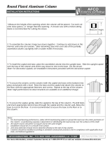
1.Measure the height of the opening where the column will be placed. Cut each col-
umn stave (piece)
1/4” longer than the opening. A circular saw with a metal cutting
blade is recommended for cutting the staves.
2.
T
o assemble the column, hinge two staves together. Continue to add staves in this
manner until only one remains. Slide remaining stave into each side of the partially
assembled column, tap lightly with a rubber mallet if necessary.
4.
T
o secure the column, set the column (with the capital and base at the bottom) into
place and plumb with a level. Raise the base and the capital and attach the column to
the floor with the appropriate fasteners and screws. Repeat at the top of the column.
Note: High performance tie down brackets are available at an additional charge.
5. To secure the capital, gently, slide the capital to the top of the column. Pre-drill holes
and insert appropriate sized screws through the capital and the column wall. Allow the
base to rest on the floor. It is not recommended to secure the base to the floor or to
the column.
Notes:
a. For best load-bearing performance, utilize AFCO load-bearing plates to spread the load over the entire perimeter of
the column. Load-bearing capacity is dependent on distributing the load evenly over the surfaces of the shaf
t.
b
. All column staves should be cut square and to the same length.
c. Installation should be on a smooth level surface.
d. 2nd story balconies should not be attached directly to the side of any column.
e. Columns should be installed according to standard construction practices and in compliance with applicable local,
state, and federal regulations.
3. To install the capital and base, place the assembled column into the upright base. Slide the upright capital
o
ver the top of the column and all the way down to rest on the base. Do not secure.
Note: For decorative capitals, see installation instructions provided with the decorative capital.

Round Fluted Wrap
Round Fluted Wrap
Round Fluted Wrap
-
-
-
Around Aluminum Column
Around Aluminum Column
Around Aluminum Column
INSTALLATION INSTRUCTIONS
R
OUND
F
LUTED
W
RAP
-A
ROUND
A
LUMINUM
C
OLUMN
AFCO Form AL02-R Rev.7/2013
1. Measure the height of the opening where the column will be placed. Cut each col-
umn stave (piece)
1/4” longer than the opening. A circular saw with a metal cutting
blade is recommended for cutting the staves.
2.
To assemble the column, hinge the smaller opening of the stave into the larger
o
pening of the stave. Continue to add staves in this manner around the existing post
until only one stave remains. Hinge the last modified stave to the partially assembled
column and snap into place. Tap lightly with a rubber mallet if necessary to ensure the
joint is fully engaged.
Note: The stave with the modified lip has a portion of the inter-locking
lip removed.
3
.
T
o secure the column, attach the column to the overhead beam or header with th
e
a
ppropriate fasteners and screws. Repeat this at the bottom of the column.
Note: High performance tie down brackets are available at an additional charge.
4
.
T
o assemble and install the capital and base, remove one screw from each side of th
e
b
ase. Place the two pieces of the base around the bottom of the column, flush with th
e
f
loor and re-insert the screws to secure in place. Repeat this process with the capital at
the top of the column. To secure the capital, gently slide the capital to the top of the
column. Pre-drill holes and insert appropriate sized screws through the capital and the
column wall. Be sure the capital is flush with both the header and the base.
If needed, caulk between seams for a finished look. Allow the base to rest on the floor.
It is not recommended to secure the base to the floor.
Note: For decorative capitals, see installation instructions provided with the decorative
capital.
Notes:
a. This column is not load-bearing.
b. All column staves should be cut square and to the same length.
c. Installation should be on a smooth level surface.
d. 2nd story balconies should not be attached directly to the side of any column.
e. Columns should be installed according to standard construction practices and in compliance with applicable local,
state, and federal regulations.
SIZE CHART
C
OLUMN
S
IZE
S
TAVES
P
ER
C
OLUMN
M
AXIMUM
S
IZE
OF
E
XISTING
R
OUND
P
OST
M
AXIMUM
S
IZE
OF
E
XISTING
S
QUARE
P
OST
12
5 9
3/4” 7 1/2”
15
5
12” 9”
18
6
15” 11”
24
6 22
1/4” 15 1/2”

INSTALLATION INSTRUCTIONS
R
OUND
F
LUTED
6” & 8” S
NAP
-T
OGETHER
A
LUMINUM
C
OLUMN
AFCO Form AL03-R Rev. 7/2013
1. Measure the height of the opening where the column will be placed. Cut each col-
umn stave (piece)
1/4” longer than the opening. A circular saw with a metal cutting
blade is recommended for cutting the staves.
2.
To assemble the column, snap the interlocks of two staves together beginning at one
en
d and continuing along the length of the column. Add staves in the same manne
r
u
ntil column shaft is complete. Tap lightly with a rubber mallet if necessary.
For wrap-around-post installation: Follow above instructions but add final stave with
the partially assembled column in an upright position around the interior post.
3.
To secure the column, attach the column to the overhead beam or header with the
a
ppropriate fasteners and screws. Repeat this at the bottom of the column.
For whole capital and base: Before putting the column into position, place the assem-
bled column in the upright base. Slide the capital over the top of the column and all
th
e way down to rest on the base. Then, set the column with the capital and base into
place and plumb with a level. Secure the column.
Note: High performance tie down brackets are available at an additional charge.
4. To assemble and install the split capital and base, place the two pieces of the base
around the bottom of the secured column, flush with the floor and secure together
with PVC glue. Repeat this process with the capital at the top of the column. Be sure
the capital is flush with both the header and the base.
For whole capital and base: To secure the capital to the top of the secured column, pre-
drill holes and insert appropriate sized screws through the capital and the column wall.
Installer may elect to use an optional installation method by securing the capital in
place with construction adhesive. If needed, caulk between seams for a finished look.
Allow the base to rest on the floor. It is not recommended to secure the whole base to
the floor or to the column.
Note: For decorative capitals, see installation instructions provided with the decorative
capital.
Notes:
a. For best load-bearing performance, utilize AFCO load-bearing plates to spread the load over the entire perimeter of
the column. Load-bearing capacity is dependent on distributing the load evenly over the surfaces of the shaf
t.
b
. All column staves should be cut square and to the same length.
c. Installation should be on a smooth level surface.
d. 2nd story balconies should not be attached directly to the side of any column.
e. Columns should be installed according to standard construction practices and in compliance with applicable local,
state, and federal regulations.
SIZE CHART
C
OLUMN
S
IZE
S
TAVES
P
ER
C
OLUMN
M
AXIMUM
S
IZE
OF
E
XISTING
R
OUND
P
OST
M
AXIMUM
S
IZE
OF
E
XISTING
S
QUARE
P
OST
6 3 4
1/2” 3 1/2”
8 3 6
1/4” 4 1/2”
Round Fluted 6” & 8” Snap
Round Fluted 6” & 8” Snap
Round Fluted 6” & 8” Snap
-
-
-
Together Aluminum Column
Together Aluminum Column
Together Aluminum Column

Decorative Aluminum Capitals
Decorative Aluminum Capitals
Decorative Aluminum Capitals
INSTALLATION INSTRUCTIONS
D
ECORATIVE
A
LUMINUM
C
APITALS
AFCO Form AL10-DC Rev. 7/2013
Note: These instructions supplement the Round Fluted Aluminum Column Installation Instructions.
1. Follow the appropriate installation instructions for measuring, cutting, assembly, and securing the column.
Note: When measuring and cutting staves, allow for the additional height added by the decorative capital.
2. Place the capital on floor, stand the assembled column in ring of capital. Using
a
1/8” bit, drill holes in the column to align with the predrilled holes of the capital.
Use the provided screws to secure the capital to the column.
3.
Place the assembled column on its side, then slide the base on the column
shaft. Ensure the base aligns with the capital (do not secure).
4.
Set column in place and plumb with a level. Attach the capital to the upper
structure by inserting the appropriate screws, thru pre-drilled holes in the ceiling
end of the capital.
5.
Caulk and paint as necessary to hide the seams and screw heads.
Notes:
a. For best load-bearing performance, utilize AFCO load-bearing plates to spread the load over the entire perimeter of
the column. Load-bearing capacity is dependent on distributing the load evenly over the surfaces of the shaf
t.
b
. All column staves should be cut square and to the same length.
c. Installation should be on a smooth level surface.
d. 2nd story balconies should not be attached directly to the side of any column.
e. Columns should be installed according to standard construction practices and in compliance with applicable local,
state, and federal regulations.

Decorative Split Aluminum Capitals
Decorative Split Aluminum Capitals
Decorative Split Aluminum Capitals
INSTALLATION INSTRUCTIONS
D
ECORATIVE
S
PLIT
A
LUMINUM
C
APITAL
AFCO Form AL11-DC Rev. 7/2013
Note: These instructions supplement the Round Wrap-Around Aluminum Column Installation Instructions
and the Round Fluted Snap-Together Aluminum Column Installation Instructions.
1. Follow the appropriate installation instructions for measuring, cutting, assembly, and securing the column.
Note: When measuring and cutting staves, allow for the additional height added by the decorative capital.
2. When preparing to install, ensure that the capital halves remain in pairs as
received. Place one half of the split capital in place around the top of the col-
umn. Insert the appropriate screws, into the pre-drilled holes to attach the capi-
tal to the upper structure.
3.
Repeat for the second half of the capital. Adjust as necessary to minimize any gaps at the seams.
4.
U
sing a
1/8” bit, drill holes in the staves to align with the predrilled holes in
the capital. Use the provided screws to secure the capital to the column.
5.
Caulk and paint as necessary to hide the seams and screw heads.
Notes:
a. For best load-bearing performance, utilize AFCO load-bearing plates to spread the load over the entire perimeter of
the column. Load-bearing capacity is dependent on distributing the load evenly over the surfaces of the shaf
t.
b
. All column staves should be cut square and to the same length.
c. Installation should be on a smooth level surface.
d. 2nd story balconies should not be attached directly to the side of any column.
e. Columns should be installed according to standard construction practices and in compliance with applicable local,
state, and federal regulations.

Decorative Aluminum Capitals
Decorative Aluminum Capitals
Decorative Aluminum Capitals
INSTALLATION INSTRUCTIONS
D
ECORATIVE
A
LUMINUM
C
APITALS
AFCO Form AL10-DC Rev. 7/2013
Note: These instructions supplement the Round Fluted Aluminum Column Installation Instructions.
1. Follow the appropriate installation instructions for measuring, cutting, assembly, and securing the column.
Note: When measuring and cutting staves, allow for the additional height added by the decorative capital.
2. Place the capital on floor, stand the assembled column in ring of capital. Using
a
1/8” bit, drill holes in the column to align with the predrilled holes of the capital.
Use the provided screws to secure the capital to the column.
3.
Place the assembled column on its side, then slide the base on the column
shaft. Ensure the base aligns with the capital (do not secure).
4.
Set column in place and plumb with a level. Attach the capital to the upper
structure by inserting the appropriate screws, thru pre-drilled holes in the ceiling
end of the capital.
5.
Caulk and paint as necessary to hide the seams and screw heads.
Notes:
a. For best load-bearing performance, utilize AFCO load-bearing plates to spread the load over the entire perimeter of
the column. Load-bearing capacity is dependent on distributing the load evenly over the surfaces of the shaf
t.
b
. All column staves should be cut square and to the same length.
c. Installation should be on a smooth level surface.
d. 2nd story balconies should not be attached directly to the side of any column.
e. Columns should be installed according to standard construction practices and in compliance with applicable local,
state, and federal regulations.

Decorative Split Aluminum Capitals
Decorative Split Aluminum Capitals
Decorative Split Aluminum Capitals
INSTALLATION INSTRUCTIONS
D
ECORATIVE
S
PLIT
A
LUMINUM
C
APITAL
AFCO Form AL11-DC Rev. 7/2013
Note: These instructions supplement the Round Wrap-Around Aluminum Column Installation Instructions
and the Round Fluted Snap-Together Aluminum Column Installation Instructions.
1. Follow the appropriate installation instructions for measuring, cutting, assembly, and securing the column.
Note: When measuring and cutting staves, allow for the additional height added by the decorative capital.
2. When preparing to install, ensure that the capital halves remain in pairs as
received. Place one half of the split capital in place around the top of the col-
umn. Insert the appropriate screws, into the pre-drilled holes to attach the capi-
tal to the upper structure.
3.
Repeat for the second half of the capital. Adjust as necessary to minimize any gaps at the seams.
4.
U
sing a
1/8” bit, drill holes in the staves to align with the predrilled holes in
the capital. Use the provided screws to secure the capital to the column.
5.
Caulk and paint as necessary to hide the seams and screw heads.
Notes:
a. For best load-bearing performance, utilize AFCO load-bearing plates to spread the load over the entire perimeter of
the column. Load-bearing capacity is dependent on distributing the load evenly over the surfaces of the shaf
t.
b
. All column staves should be cut square and to the same length.
c. Installation should be on a smooth level surface.
d. 2nd story balconies should not be attached directly to the side of any column.
e. Columns should be installed according to standard construction practices and in compliance with applicable local,
state, and federal regulations.

Acadian, Craftsman, Empire & Square Fluted Aluminum Columns
Acadian, Craftsman, Empire & Square Fluted Aluminum Columns
Acadian, Craftsman, Empire & Square Fluted Aluminum Columns
INSTALLATION INSTRUCTIONS FOR ALL SIZES
A
CADIAN
, C
RAFTSMAN
, E
MPIRE
& S
QUARE
F
LUTED
A
LUMINUM
C
OLUMNS
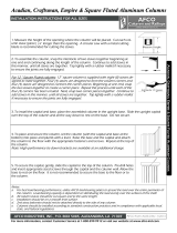
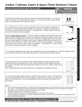
1. Measure the height of the opening where the column will be placed. Cut each col-
umn stave (piece)
1/4” longer than the opening. A circular saw with a metal cutting
blade is recommended for cutting the staves.
2.
T
o assemble the column, snap the interlocks of two staves together beginning at
one end and continuing along the length of the column. Continue to add staves in
this manner, until all staves are together. Tap lightly with a rubber mallet if necessary
to ensure the joints are fully engaged.
For 12 “ Square Fluted columns: 12” square column is supplied with eight (8) staves de-
signed to mate together. Four (4) staves are designed to form the column corners and
four (4) staves are designed to connect the corner pieces. Beginning at one end, snap
the two staves together to create a corner piece. Repeat this process until each of the
four (4) corners has been created. Next, snap two corner pieces together. Continue to
add staves in this manner, until all staves are together. Tap lightly with a rubber mallet
if necessary to ensure the joints are fully engaged.
4. To place and secure the column, set the column (with the capital and base at the
bottom) into place and plumb with a level. Raise the base and the capital and attach
the column to the floor with the appropriate fasteners and screws. Repeat at the top of
the column.
Note: High performance tie down brackets are available at an additional charge.
5
.
T
o secure the capital, gently, slide the capital to the top of the column. Pre-drill holes
and insert appropriate sized screws through the capital and the column wall. Allow the
base to rest on the floor. It is not recommended to secure the base to the floor or to
the column.
Notes:
a. For best load-bearing performance, utilize AFCO load-bearing plates to spread the load over the entire perimeter of
the column. Load-bearing capacity is dependent on distributing the load evenly over the surfaces of the shaf
t.
b
. All column staves should be cut square and to the same length.
c. Installation should be on a smooth level surface.
d. 2nd story balconies should not be attached directly to the side of any column.
e. Columns should be installed according to standard construction practices and in compliance with applicable local,
state, and federal regulations.
3. To install the capital and base, place the assembled column in the upright base. Slide the upright capital
o
ver the top of the column and all the way down to rest on the base. Do not secure.

Acadian Wrap
Acadian Wrap
Acadian Wrap
-
-
-
Around Aluminum Column
Around Aluminum Column
Around Aluminum Column
INSTALLATION INSTRUCTIONS
A
CADIAN
W
RAP
-A
ROUND
A
LUMINUM
C
OLUMN
1. Measure the height of the opening where the column will be placed. Cut each col-
umn stave (piece)
1/4” longer than the opening. A circular saw with a metal cutting
blade is recommended for cutting the staves.
2.
T
o assemble the column, snap the interlocks of two staves together beginning at
one end and continuing along the length of the column. This will form half of th
e
c
olumn. Repeat this process with two more staves to form the other half of the col-
umn. Tap lightly with a rubber mallet if necessary to insure the joint is fully engaged.
3.
T
o install the capital and base, place each half of the base onto half of the column.
Place each half of the capital onto half of the column. Snap the two halves of the col-
umn with the base and capital together. For wrap around post installation, assemble
the column in an upright position around interior post. Tap lightly with a rubber mal-
let if necessary to ensure the joints are fully engaged.
4.
T
o secure the column, gently slide the capital away from the top of the column. At-
tach the column to the overhead beam or header with the provided fasteners and
screws. Repeat this at the bottom by gently sliding the base up and securing the col-
umn to the floor.
Note: High performance tie down brackets are available at an additional charge.
5. To secure the capital, gently, slide the capital to the top of the column. Pre-drill holes
and insert appropriate sized screws through the capital and the column wall. Allow the
base to rest on the floor. It is not recommended to secure the base to the floor or to
the column. If needed, caulk between seams for a finished look.
Note: An optional decorative block kit is available for the Acadian Wrap-Around Aluminum Column. See installation in-
Notes:
a. For best load-bearing performance, utilize AFCO load-bearing plates to spread the load over the entire perimeter of
the column. Load-bearing capacity is dependent on distributing the load evenly over the surfaces of the shaf
t.
b
. All column staves should be cut square and to the same length.
c. Installation should be on a smooth level surface.
d. 2nd story balconies should not be attached directly to the side of any column.
e. Columns should be installed according to standard construction practices and in compliance with applicable local,
state, and federal regulations.
SIZE CHART
C
OLUMN
S
IZE
S
TAVES
P
ER
C
OLUMN
M
AXIMUM
S
IZE
OF
E
XISTING
R
OUND
P
OST
M
AXIMUM
S
IZE
OF
E
XISTING
S
QUARE
P
OST
6 4 4–
1/2” 4– 1/2” X 4– 1/2”
8 4
5-
3/4” 5- 3/4” X 5- 3/4”


Square Wrap
Square Wrap
Square Wrap
-
-
-
Around Aluminum Column
Around Aluminum Column
Around Aluminum Column
INSTALLATION INSTRUCTIONS
S
QUARE
W
RAP
-A
ROUND
A
LUMINUM
C
OLUMN
AFCO Form ALO6-S Rev. 7/2013
1. Measure the height of the opening where the column will be placed. Cut each col-
umn stave (piece)
1/4” longer than the opening. A circular saw with a metal cutting
blade is recommended for cutting the staves.
2.
To assemble the column, snap the interlocks of two staves together beginning at
one end and continuing along the length of the column. Continue to add staves in
this manner, until all staves are together. Tap lightly with a rubber mallet if necessary
to ensure the joints are fully engaged. For wrap-around-post installation follow abov
e
i
nstructions but add final stave with the partially assembled column in an upright posi-
tion around the interior post.
3.
To secure the column, attach the column to the overhead beam or header with the
a
ppropriate fasteners and screws. Repeat this at the bottom of the column.
Note: High performance tie down brackets are available at an additional charge.
4
.
T
o assemble and install the capital and base, place the two pieces of the base around
the bottom of the column, flush with the floor and insert the provided screws to secure
in place. Repeat this process with the capital at the top of the column. Be sure the cap-
ital is flush with both the header and the base. If needed, caulk between seams for
a
fi
nished look.
Notes:
a. For best load-bearing performance, utilize AFCO load-bearing plates to spread the load over the entire perimeter of
the column. Load-bearing capacity is dependent on distributing the load evenly over the surfaces of the shaf
t.
b
. All column staves should be cut square and to the same length.
c. Installation should be on a smooth level surface.
d. 2nd story balconies should not be attached directly to the side of any column.
e. Columns should be installed according to standard construction practices and in compliance with applicable local,
state, and federal regulations.
C
OLUMN
S
IZE
S
TAVES
P
ER
C
OLUMN
M
AXIMUM
S
IZE
OF
E
XISTING
R
OUND
P
OST
M
AXIMUM
S
IZE
OF
E
XISTING
S
QUARE
P
OST
4 2
3” 3”
6 4 4
7/8” 4 1/2”
SIZE CHART
8 4 6
7/8” 6 1/2”
10
4 8
1/2” 8 1/2”
12
8
10” 10”

Wellington Aluminum Column
Wellington Aluminum Column
Wellington Aluminum Column
INSTALLATION INSTRUCTIONS
W
ELLINGTON
A
LUMINUM
C
OLUMN
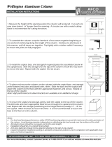
1. Measure the height of the opening where the column will be placed. Cut each col-
umn stave (piece)
1/4” longer than the opening. A circular saw with a metal cutting
blade is recommended for cutting the staves.
2.
T
o assemble the column, snap the interlocks of two staves together beginning at
one end and continuing along the length of the column. Continue to add staves in
this manner, until all staves are together. Tap lightly with a rubber mallet if necessary
to ensure the joints are fully engaged.
4.
T
o place and secure the column, set the column (with the capital base, and astragal
at the bottom) into place and plumb with a level. Raise the base and the capital and
attach the column to the floor with the appropriate fasteners and screws. Repeat at
the top of the column.
Note: High performance tie down brackets are available at an additional charge.
5
.
T
o secure the capital and astragal, gently, slide the capital to the top of the column.
Pre-drill holes and insert appropriate sized screws through the capital and the column
wall. Repeat with the astragal, positioning at the height desired (usually 12” - 18” be-
low capital. Allow the base to rest on the floor. It is not recommended to secure the
base to the floor or to the column.
Notes:
a. For best load-bearing performance, utilize AFCO load-bearing plates to spread the load over the entire perimeter of
the column. Load-bearing capacity is dependent on distributing the load evenly over the surfaces of the shaf
t.
b
. All column staves should be cut square and to the same length.
c. Installation should be on a smooth level surface.
d. 2nd story balconies should not be attached directly to the side of any column.
e. Columns should be installed according to standard construction practices and in compliance with applicable local,
state, and federal regulations.
3. To install the capital, base, and astragal (if required) place the assembled column in
the upright base. Slide the astragal over the top of the column and all the way down
to rest on the base. Repeat with the capital. Do not secure.

Wellington Wrap
Wellington Wrap
Wellington Wrap
-
-
-
Around Aluminum Column
Around Aluminum Column
Around Aluminum Column
INSTALLATION INSTRUCTIONS
W
ELLINGTON
W
RAP
-A
ROUND
A
LUMINUM
C
OLUMN
1. Measure the height of the opening where the column will be placed. Cut each col-
umn stave (piece)
1/4” longer than the opening. A circular saw with a metal cutting
blade is recommended for cutting the staves.
2.
T
o assemble the column, snap the interlocks of two staves together beginning at
one end and continuing along the length of the column. Continue to add staves in
this manner. Snap the final stave into place and tap lightly with a rubber mallet if nec-
essary to ensure the joint is fully engaged. For wrap-around-post installation follow
above instructions but add final stave with the partially assembled column in an up-
right position around the interior post.
3.
T
o secure the column, attach the column to the overhead beam or header with th
e
a
ppropriate fasteners and screws. Repeat this at the bottom of the column.
Note: High performance tie down brackets are available at an additional charge.
4
.
T
o assemble and install the capital and base, drill and counter-sink through flat sur-
face of both halves of the base with
1/8” bit. Install both halves to the bottom of the
column, flush with the floor, and secure them with the provided screws on all sides.
Repeat this process with the capital at the top of the column. If needed, caulk between
seams for a finished look.
To assemble and install the astragal, drill and counter-sink through flat surface of both
halves of astragal with 1/8” bit. Position at height desired (usually about 12” – 18” be-
low capital). Then attach both halves to the column, and secure them with the provid-
ed screws on all sides. If needed, caulk between seams for a finished look.
Notes:
a. For best load-bearing performance, utilize AFCO load-bearing plates to spread the load over the entire perimeter of
the column. Load-bearing capacity is dependent on distributing the load evenly over the surfaces of the shaf
t.
b
. All column staves should be cut square and to the same length.
c. Installation should be on a smooth level surface.
d. 2nd story balconies should not be attached directly to the side of any column.
e. Columns should be installed according to standard construction practices and in compliance with applicable local,
state, and federal regulations.
-
 1
1
-
 2
2
-
 3
3
-
 4
4
-
 5
5
-
 6
6
-
 7
7
-
 8
8
-
 9
9
-
 10
10
-
 11
11
-
 12
12
-
 13
13
AFCO Industries EA12SSENSBTU Installation guide
- Type
- Installation guide
Ask a question and I''ll find the answer in the document
Finding information in a document is now easier with AI
Other documents
-
Hagerco 849S - Split Astragal Installation guide
-
 AFCO EA0610ENPSPACAC Installation guide
-
 AFCO EA0810INFSFTUTU Installation guide
-
 AFCO EA0808RNFSPTUTU Installation guide
-
 AFCO EA0908INPSPWEWE Installation guide
-
 AFCO 600CA608 Installation guide
-
 AFCO 006CA608 Installation guide
-
 AFCO 175 Series Installation guide
-
 HB&G 713515 Installation guide
-
 Turncraft 2508 Dimensions Guide


