Page is loading ...

©2019. Euri Lighting | A Division of IRTRONIX Inc. All Rights Reserved
PLEASE REVIEW THE INSTRUCTIONS AND WARNINGS LISTED BELOW PRIOR TO PROPER INSTALLATION
WARNINGS CAUTIONS
•Turn off electrical power at fuse or circuit breaker before wiring fixture to the power
supply.
• Turn off the power when you perform any maintenance.
• Verify that supply voltage is correct by comparing it with theluminaire label information.
• All connections should be capped with UL approved wire connectors.
• Total number of panels allowed on a single circuit using branch circuit wiring is 18.
• Over 90 minutes emergency working time
• Avoid direct eye exposure to the light source while it is on.
• Account for small parts and destroy packing material, as these may be hazardous
to children.
• Risk of Burn. Disconnet power and allow fixture to cool before handling.
Notes FCC Notes
1. Indoor lighting only.
2. Before installation, ensure the LED panel is not damaged.
3. Don’t stare at the LED luminous surface for long time.
4. Keep away from children, and ensure working eletrical appatatus inaccessible to them.
5. No packages accessible to children, because they might be choked for playing, or
eating the small accessories.
6. No covering, be away from fire or high-temperature substance.
7. Manufacturer reserves the right to offer no replacement or warranty to the led
panels dissembled or repaired by users themselves.
8. Cut off power before cleaning the panels with dry cloth, use no chemical or
corrosive substance.
9. Cut off power before installation.
10. The light source of this luminaire is not replaceable; when the light source reaches
its end of life the whole luminaire shall be replaced.
This product must be installed in accordance with the applicable installation code by
a person familiar with the construction and operation of the product and the hazards
involved min 90°C supply conductors.
This device complies with Part 15 of the FCC Rules. Operation is subject to the
following two conditions:
(1) this device may not cause harmful interference, and (2) this device must accept
any interference received, including interference that may cause undesired operation.
Changes or modifications to this unit not expressly approved by the party responsible
for compliance could void the user’s authority to operate the equipment.
NOTE: This equipment has been tested and found to comply with the limits for a Class
B digital device, pursuant to Part 15 of the FCC Rules. These limits are designed to
provide reasonable protection against harmful interference in a residential installation.
This equipment generates, uses and can radiate radio frequency energy and, if not
installed and used in accordance with the instructions, may cause harmful interference
to radio communications. However, there is no guarantee that interference will not
occur in a particular installation. If this equipment does cause harmful interference
to radio or television reception, which can be determined by turning the equipment off
and on, the user is encouraged to try to correct the interference by one or more of the
following measures:
- Reorient or relocate the receiving antenna.
- Increase the separation between the equipment and receiver.
- Connect the equipment into an outlet on a circuit different from that to which the
receiver is connected.
- Consult the dealer or an experienced radio/ TV technician for help.
INSTALLATION INSTRUCTIONS - Wiring Instructions
CONTINUES ON REVERSE
For customer service please call us at 1-310-787-3280
Office Hours: 8:00 a.m. – 5:00 p.m. PST Monday-Friday
Questions?
LED Panel Series | 2x4 Class
2 ft x 4 ft. Emergency Panel Light
LED
Panel
2 ft. x 4 ft.
INSTALLATION GUIDE
MODEL #: EPN24-2040sem-2 / EPN24-2050sem-2

For customer service please call us at 1-310-787-3280
Office Hours: 8:00 a.m. – 5:00 p.m. PST Monday-Friday
Questions?
LED Panel Series | 2x4 Class
2 ft x 4 ft. Emergency Panel Light
LED
Panel
2 ft. x 4 ft.
INSTALLATION GUIDE
MODEL #: EPN24-2040sem-2 / EPN24-2050sem-2
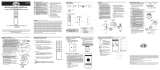
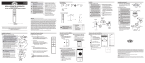
Drop Ceiling Installation Steps
Recessed Frame Installation
The automatic test function is controlled by internal single chip microcomputer.
Depending on the luminescent color of the LED indicator,
It displays the working state and determines whether there is an exception.
Red stable: charging mode
Red and Green off: discharging mode or mains supply disconnected
Green stable: battery fully charged
Red flashing: failure as below
Battery is not connected
Battery is defective
Load failure during emergency mode, open circuit/short circuit
Color
State
Test switch
Under normal working condition, the lamp will enter the discharge state by pressing the test switch.
Release the switch and automatically return to the charging state.
In the discharge mode, the discharge will be switched off according to the test switch for more than 3 seconds.
3
4
5
1. Check the fitting bag against the parts list.
2. Compare celling against specifications to ensure ceiling meets installation rquirements. See chart below.
3. Remove ceiling panel down. 4. Insert fixture at an angle up into
ceiling and lower into place.
5. Confirm that fixture in seated
flush in the celing channels
/