Page is loading ...

Page 1
INSTALLATION INSTRUCTIONS
CONTEMPORARY
LINEAR VENT-FREE
GAS FIREPLACE MODEL
VFLB(60,72)FP90(N,P)-1
This appliance may be installed in an aftermarket,
permanently located, manufactured (mobile) home,
where not prohibited by local codes.
This appliance is only for use with the type of gas
indicated on the rating plate. This appliance is not
convertible for use with other gases.
INSTALLER:
Leave this manual with the appliance.
CONSUMER:
Retain this manual for future reference.
WARNING
If the information in this manual is not
followed exactly, a re or explosion may
result causing property damage, personal
injury or loss of life.
— Do not store or use gasoline or other
ammable vapors and liquids in the
vicinity of this or any other appliance.
— WHAT TO DO IF YOU SMELL GAS
• Do not try to light any appliance.
• Do not touch any electrical switch;
do not use any phone in your building.
• Immediately call your gas supplier
from a neighbor’s phone. Follow
the gas supplier’s instructions.
• If you cannot reach your gas
supplier, call the re department.
— Installation and service must be
performed by a qualied installer,
service agency or the gas supplier.
WARNING
"FIRE, EXPLOSION, AND ASPHYXIATION HAZARD
Improper adjustment, alteration, service,
maintenance or installation of this heater or
its controls can cause death or serious injury.
Read and follow instructions and precautions
in User's Information Manual provided with
this heater."
This is an unvented gas-red heater. It uses air
(oxygen) from the room in which it is installed.
Provisions for adequate combustion and
ventilation air must be provided.
Refer to pages 15.
This series is design certied in
accordance with American National
Standard Institute (ANSI) Z21.11.2
by the Canadian Standards
Association Laboratories (CSA)
as an Unvented Room Fireplace
and should be installed according
to these instructions.
GAS-FIRED
UL FILE NO. MH46389

Page 2 40216-1-0120
TABLE OF CONTENTS
Before You Start ....................................................................................................................................3 - 4
Carton Contents ......................................................................................................................................... 5
Hardware Pack ........................................................................................................................................... 6
Important Soot Prevention Steps ............................................................................................................... 7
Product Specications ................................................................................................................................ 8
Homeowner Reference Information ........................................................................................................... 8
Accessories ................................................................................................................................................ 9
Introduction .............................................................................................................................................. 10
Important Safety Information .................................................................................................................... 11
Safety Information for Users of Propane Gas .......................................................................................... 12
Important Installation Guidelines .............................................................................................................. 13
Water Vapor: A By-Product of Unvented Room Heaters .......................................................................... 13
Provisions for Adequate Combustion And Ventilation Air ...................................................................14 -15
Fireplace Dimensions ............................................................................................................................... 16
Clearances ............................................................................................................................................... 17
Adding Nailing Flanges And Standoff Brackets ................................................................................. 18 - 19
Utility Installation ...............................................................................................................................20 - 24
Installation OPTION 1 - Clean Face ......................................................................................................... 25
OPTION 1 - Clean Face (Non - Combustible Board Installation) ...................................................... 26 - 28
Installation OPTION 2 - Flush Mount ....................................................................................................... 29
OPTION 2 - Flush Face (Non - Combustible Board Installation) ......................................................30 - 32
Completing Installation ...................................................................................................................... 33 - 34
Lighting Instructions ................................................................................................................................. 35
Pilot Flame Characteristics ...................................................................................................................... 36
Proame - IP Control System ...................................................................................................................37
Trouble Shooting ...............................................................................................................................38 - 41
VFLB(60,72)FP90 - Exploded View .........................................................................................................42
VFLB(60,72)FP90 - Parts List .................................................................................................................. 43
Service Technician Notes .................................................................................................................. 44 - 45
Master Parts Distributor List ..................................................................................................................... 46
How To Order Repair Parts ......................................................................................................................46
Warranty ................................................................................................................................................... 47
SECTION PAGE

40216-1-0120 Page 3
UNPACKING THE FIREPLACE
1. Remove the six screws securing the plywood top to the
corner supports. Remove the plywood top and discard.
2.
Remove the two screws securing each side of the corner
and center supports to the pallet. Remove the corner and
center supports and discard.
3. Cut the banding securing the replace to the pallet.
Discard the banding.
NOTICE
SHEET
GLASS LABEL
FRAGILE LABEL
CARTON LABEL
Figure 1
4.
Remove the plastic wrap securing the hardware box to the
replace. Discard the plastic wrap. Open the hardware box,
remove the instruction packet, and set the hardware box to side.
HARDWARE
INSTRUCTIONS
(INSIDE BOX)
Figure 2
5. Carefully remove the bundle from inside the replace. This
bundle contains two center glass supports and the burner
deector glass. Put the bundle in an out of the way place to
avoid damaging the components.
6. Lift the replace off the pallet and place it near the
installation site. If the replace must be placed on end so
that a hand truck may be used for transportation, remove all
loose components from inside the replace. Truck from the
left end (when facing the replace opening) only.
7. Remove the non-combustible board from the pallet.
NOTICE:
Non-combustible board is required for installation
above the replace as specied in the installation instructions.
BEFORE YOU START

Page 4 40216-1-0120
BEFORE YOU START (CONT'D)
SAMPLE WARNINGS AND DEFINITIONS:
DANGER
Indicates a hazardous situation which, if not avoided, will
result in death or serious injury.
WARNING
Indicates a hazardous situation which, if not avoided, could
result in death or serious injury.
CAUTION
Indicates a hazardous situation which, if not avoided, could
result in minor or moderate injury.
NOTICE: Addresses practices not related to personal injury.
INSTALLATION INFORMATION
1. Read the soot prevention information on page 7.
2. Read the safety information on pages 11 - 12.
3. Frame the opening. See page 26 for Clean Face Installation,
or page 30 for Flush Mount Installation.
4. Install the gas lines. See pages 20 - 22.
5. Install the wiring. See pages 22 - 24.
6. Install the remote system. See pages 37.
7. Light the replace. See page 35.
8. For detailed instructions on operating the Proame - IP
Control System, see page 37 and Homeowner's Manual.
9. For detailed instructions on operating LED controls, (see
Homeowner's Manual.)
10. Show the homeowner how to operate the replace.
(See Homeowner's Manual.)
11. Show the homeowner how to do the basic maintenance.
(See Homeowner's Manual.)
FIREPLACE INSTALLATION GUIDELINES
Determine where to install the replace. The replace can be
mounted on any of these surfaces:
1. A at hard combustible or non-combustible surface.
2. A raised platform of combustible or non-combustible
material.
If the replace is installed directly on carpeting, tile or other
combustible material other than wood ooring, it must be installed
on a metal or wood panel extending the full width and depth of
the replace.
This replace is designed to be installed in a zero-clearance
enclosure. This means combustible material such as framing
lumber can come in contact with the top and side standoff
spacers, and secured to combustible framing using the framing
brackets provided.
This replace requires an easily accessible gas shutoff valve be
installed in the gas supply line prior to its entry to the replace.
Determine the following before installation:
• Any desired accessories
• Gas supply piping (left side entrance).
• Electrical connections
• Electrical supply requirements for lights.
(120V, 60Hz, 1 Amp) (left side entrance)
A shut-off valve containing a ange and key is recommended.
FINISHING OPTIONS
Choose from two nishing options.
Option 1 - Clean Face: This type of installation starting on
(pages 25, 26, 27 and 28) will allow for nishing around the
replace opening with high temperature paint.
Option 2 - Flush Mount: This type of installation starting on
(pages 29, 30, 31 and 32) will allow you to apply tile, marble,
stone or other non-combustible material over the face of the
replace cabinet, up to the replace opening ange.
CAUTION
PARTS MAY HAVE SHARP EDGES.
Wear leather gloves and handle parts carefully to protect
hands during unpacking, assembly, and installation.

40216-1-0120 Page 5
CARTON CONTENTS
Items not shown to scale.
VFLB(60,72)FP90 SERIES
Index
No.
Description
Quantity
Supplied
1 Fireplace 1
2 Non-combustible Board - Top 1
3 Non-combustible Board - Side* 2
4 Barrier Screen Assembly 1
5 Burner Glass 1
6 Side Burner Glass* 2
7 Bushing* 2
8 Standoff Bracket* 3
9 Receptacle* 1
10 Remote* 1
VFLB(60,72)FP90 SERIES
Index
No.
Description
Quantity
Supplied
11 AA Battery* 4
12 AAA Battery* 3
13 Hardware Pack* 1
14 AC Adaptor* 1
15 Wall mounted Control Box* 1
16 Remote Receiver* 1
17 Button Switch* 2
18 Mounting Bracket* 1
19 Wall Plate* 1
20 Glass Support Center 2
21 Glass Support Side Left* 1
22 Glass Support Side Right* 1
23 Center Reector Assembly 1
24 Extension Receiver Harness 1
25 Junction Box Cover* 1
26 Romex Connector* 1
27 Zip Tie* 1
*Items packaged inside hardware box.
For hardware pack contents, see page 6.
See Parts Lists on page 43 for ordering replacement parts. Do
not order batteries, bolts, screws, washers or nuts. They are
standard hardware items and can be purchased at any local
hardware store.
2
3
8
26
10
12
4
13
14
7
11
15
16
17
17
19
18
1
9
23
6
5
25
24
21
20
22
27
CARTON CONTENTS

Page 6 40216-1-0120
HARDWARE PACK CONTENTS
#8X1½” PHILLIPS SCREW
#10X½” HEX HEAD SCREW
NAILING FLANGE
#4X½” PHILLIPS SCREW
(Not to scale)
Description Quantity Supplied
#4 x 3/8 Phillips Pan Head Screw 4
#10 X 1/2 Phillips Hex Head Screw 14
#8 x 1 Inch Self-Drilling Drywall Screw 9
Nailing Flange 4
See Parts Lists on page 43 for replacement parts. Do not order
batteries, bolts, screws, washers or nuts. They are standard
hardware items and available at any local hardware store.
HARDWARE PACK
#4 X
3
/
8
"
PHILLIPS SCREW
#8 X 1" PHILLIPS SCREW

40216-1-0120 Page 7
IMPORTANT SOOT PREVENTION STEPS
IMPORTANT NOTICE
INSTALLER - SERVICE PERSON - HOMEOWNER
SOOT MAY BE CREATED IF THE FOLLOWING DIRECTIONS ARE NOT FOLLOWED
WARNING
Failure to keep the primary air openings of the burner clean
may result in sooting and property damage.
WARNING
Before installing in a solid-fuel burning replace, the chim-
ney ue and rebox must be cleaned of soot, creosote,
ashes and loose paint by a qualied chimney cleaner.
A vent-free replace or burner draws room air to support combustion.
Lightweight particles suspended in the air – including dust, carpet
bers, candle or tobacco smoke, and pet hair – will be drawn toward
the replace. These can lead to soot build-up on logs, replace
walls, and even walls of the room. To prevent malfunctions and
sooting, have your dealer inspect and clean each year – before
the heating season. If you have pets or excessive dust, more
frequent cleaning may be necessary. See cleaning and service
section in this manual.
WARNING
Do not allow fans to blow directly into or at the replace.
Avoid any drafts that alter burner ame patterns. Avoid any
drafts that alter burner ame patterns. Pay particular atten-
tion to ceiling fans and exhaust fans.
1. Ensure the air shutter is set to the specication. See
Figure 3 and Tables 1 and 2 on page 8.
2. Ensure burner, venturi, and air shutter are free of dirt, lint,
animal hair (i.e. cat and dog) or anything that may block the
needed air ow. See cleaning and service in homeowner
manual.
3. Do not place debris, additional logs or other articles on the
burner during operation.
4. Do not use scented air fresheners or candles while the
replace is in operation. They produce residue which may
cause soot.
6. Do not place glass media on burner or burner ports. The
glass media should only be placed as shown in Figure 56.
7. Do not use rock wool (embers) or lava rock.
8.
Avoid the use of decorative or scented candles while
the replace is in operation. Soot may be produced from
the by-products of a burning candle. Some candles also
produce soot.
9. Annual inspection and cleaning by your dealer or a qualied
service technician is recommended to prevent malfunction
and/or sooting.
10. Install decorative glass accessory according to the
instructions on pages 33 and 34.
11. Install optional logs according to the installation instructions.
Only use Empire Logs made for this replace.
12. Verify the venturi tube is not bent or distorted. The main
burner orice must be centered in the venturi tube to ensure
proper combustion and to prevent sooting.

Page 8 40216-1-0120
PRODUCT SPECIFICATIONS
TABLE 1 - AIR SHUTTER OPENING - NATURAL GAS MODELS
Model Air Shutter Opening
VFLB60FP90N 1/16 inch
VFLB72FP90N 1/16 inch
TABLE 2 - AIR SHUTTER OPENING - PROPANE GAS MODELS
Model Air Shutter Opening
VFLB60FP90P 5/16 inch
VFLB72FP90P 1/4 inch
VFLB60FP90P VFLB60FP90N VFLB72FP90P VFLB72FP90N
Input BTU/HR maximum 38,500 40,000 38,500 40,000
Input BTU/HR minimum 30,000 27,000 30,000 27,000
Orice 1.8mm #32 1.8mm #32
NOTICE: Air shutter settings are factory set and may not be altered.
GAS SUPPLY PRESSURES (inches water column)
Gas Type Maximum Minimum Manifold
Natural 10.5 7.0 3.5
Propane 13.0 11.0 10.0
HOMEOWNER REFERENCE INFORMATION
We recommend that you record the following information about your replace.
Model Number: _____________________________ Date purchased: ________________________
Serial Number: _____________________________ Location of replace: _____________________
Dealer Name: ______________________________ Dealer Phone: _________________________
Notes: ______________________________________________________________________________
Figure 3
(Measure opening using drill bit.) Set air shutter opening using
suitable round object such as a drill bit. The object should barely
slide between the opening.
Add Serial Number Sticker Here

40216-1-0120 Page 9
ACCESSORIES
REQUIRED ACCESSORIES
ACCESSORIES FOR VFLB(60,72)FP90(N,P)-1
PART NUMBER
DESCRIPTION
VFLB60 VFLB72
DG1CLF DG1CLF Decorative Glass, Crushed - Clear Frost (One kit per one square foot) Recommended
DG1BKP DG1BKP Decorative Glass, Crushed - Black Polished (One kit per one square foot)
DG1BUC DG1BUC Decorative Glass, Crushed - Blue Clear (One kit per one square foot)
DG1BCR DG1BCR Decorative Glass, Crushed - Copper Reective (One kit per one square foot)
DG1BZR DG1BZR Decorative Glass, Crushed - Bronze Reective (One kit per one square foot)
NOTICE: Decorative crushed glass is required for installation. Clear Frost is recommended. Decorative Glass Droplets can be mixed with
crushed glass, but cannot be substituted for crushed glass. One box of crushed glass covers 1 sq. ft. Glass colors can be mixed, and
transparent and translucent crushed glass makes LED lights more visible.
NOTICE: Requires ve square feet for VFLB60, six square feet for VFLB72.
NOTICE: Never place decorative media material on or next to the burner.
OPTIONAL ACCESSORIES
ACCESSORIES FOR VFLB(60,72)FP90(N,P)-1
PART NUMBER
DESCRIPTION
VFLB60 VFLB72
DF601VBL DF721VBL Decorative Front, Beveled, 3/4 inch, Black
DF602VBL DF722VBL Decorative Front, Beveled, 1 1/2 inch, Black
VBP60LKR VBP72LKR Liner - Black Reective Glass
VBP60LSS VBP72LSS Liner – Stainless Steel
LS60DF LS72DF Log Set
DG1GC DG1GC Decorative Glass Droplets - 1/2 inch Glacier Ice (Used as accent only)
DG1SL DG1SL Decorative Glass Droplets - 1/2 inch Sangria Luster (Used as accent only)
DG1NXS DG1NXS Decorative Glass Drops - 1 inch Onyx Solid (Used as accent only)
DG1TZC DG1TZC Decorative Glass Drop - 1 inch Topaz Clear (Used as accent only)
DRFPA DRFPA Decorative Rock, Ceramic Fiber - Pebble (Used as accent only)
NOTICE: If installing a decorative front, an offset between the nishing materials and replace opening is required. Refer to pages 27 and
31 as well as the installation instructions provided with the decorative front for more information.

Page 10 40216-1-0120
INTRODUCTION
The term qualied agency means any individual, rm, corporation
or company which either in person or through a representative
is engaged in and is responsible for (a) the installation or
replacement of gas piping or (b) the connection, installation,
repair or servicing of equipment, who is experienced in such
work, familiar with all precautions required and has complied
with all the requirements of the authority having jurisdiction.
Commonwealth of Massachusetts: The installation must be
made by a licensed plumber or gas tter in the Commonwealth
of Massachusetts.
Sellers of unvented propane or natural gas-red supplemental
replaces shall provide to each purchaser a copy of 527 CMR
30 upon sale of the unit.
In the Commonwealth of Massachusetts, unvented propane
and natural gas-red space heaters shall be prohibited in
bedrooms and bathrooms.
The installation must conform with local codes or, in the absence
of local codes, with the National Fuel Gas Code, ANSI Z223.1.*/
NFPA 54.
*Available from the American National Standards Institute, Inc.
1430 Broadway, New York, N.Y. 10018.
WARNING
Failure to keep the primary air opening(s) of the burner(s)
clean may result in sooting and property damage.
FOR THE INSTALLER
• Installation and repair should be done by a qualied service
person. The replace should be inspected before use and at
least annually by a qualied service person. More frequent
cleaning might be required due to excessive lint from
carpeting, bedding material, etc. It is imperative that control
compartments, burners and circulating air passageways
of the replace be kept clean. Keep burner and control
compartment clean.
• An unvented room replace having an input rating of more
than 6,000 Btu per hour shall not be installed in a bathroom
• An unvented room fireplace having an input rating of
more than 10,000 Btu per hour shall not be installed in a
bedroom or bathroom.
• Use Non-Combustible Materials where indicated for the
replace installation. Non-combustible material do not
ignite or burn as a result of using the replace. These
include metal, brick, ceramic, concrete, slate, glass, and
plaster. Adhesives must be rated for high temperatures. Any
mechanical fasteners used to install material must also be
non-combustible, including wall anchors and tile spacers.
Materials that pass the ASTM E 136 test (Standard Test
Method for Behavior of Materials in a Vertical Tube Furnace
at 750C) are considered non-combustible.
• Install the replace out of household trafc and away from
furniture and draperies. The high temperatures produced by
the replace create an ignition risk.
INSTRUCTIONS TO INSTALLER
1. Leave instruction manual with owner after installation.
2. Have owner register online or ll out and mail the Product
Registration Card supplied with the unvented replace.
3. Fill out Homeowner Reference Information on page 8.
4. Show homeowner how to start and operate the replace.
5. Show homeowner basic maintenance.
Consult the local Building Department regarding regulations,
codes or ordinances which apply to the installation of an
unvented replace.
This replace may be installed in an aftermarket* manufactured
(mobile) home, where not prohibited by state or local codes.
*Aftermarket: Completion of sale, not for purpose of resale,
from the manufacturer.
WELL HEAD GAS INSTALLATIONS
Some natural gas utilities use “well head” gas. This may affect
the Btu output of the unit and promote sooting. Units shall not be
converted to use well head gas.
This appliance is only for use with the type of gas indicated on the
rating plate. This appliance is not convertible for use with other gases.
WARNING
Any change to this replace or its controls can be dangerous.
Improper installation or use of the replace can cause
serious injury or death from re, burns, explosion or carbon
monoxide poisoning.
This replace is intended for supplemental heating.
Any alteration of the original design, installed other than as
shown in these instructions or use with a type of gas not shown
on the rating plate is the responsibility of the person and
company making the change.
IMPORTANT
All correspondence should refer to complete Model Number,
Serial Number and type of gas. (See page 8.)
WARNING
This appliance is equipped for natural or propane gas. Field
conversion is not permitted.
During manufacture, this replace is treated with oils, lms and
bonding agents. These are not harmful but may produce smoke
and odor as they burn off during initial operation. This is normal.
Open window to vent any smoke or odor.
INSTALLATION ON RUGS AND TILE
If this replace is installed directly on carpeting, tile or other
combustible material other than wood ooring the replace shall
be installed on a metal or wood panel extending the full width and
depth of the replace.
QUALIFIED INSTALLING AGENCY
Installation and replacement of gas piping, gas utilization
equipment or accessories and repair and servicing of equipment
shall be performed only by a qualied agency.

40216-1-0120 Page 11
WARNING
When used without adequate combustion and ventilation air,
appliance may give off CARBON MONOXIDE, an odorless,
poisonous gas.
Do not install appliance until all necessary provisions are
made for combustion and ventilation air. Consult the written
instructions provided with the appliance for information
concerning combustion and ventilation air. In the absence
of instructions, refer to the National Fuel Gas Code, ANSI
Z223.1/NFPA 54, Air for Combustion and Ventilation, or
applicable local codes.
This appliance is equipped with a PILOT LIGHT SAFETY
SYSTEM designed to turn off the appliance if not enough
fresh air is available.
The pilot light safety system senses the depletion of oxygen at
its location. If this replace is installed in a structure having a
high vertical dimension, the possibility exists that the oxygen
supply at the higher levels will be less than that at the replace.
In this type of application, a fan to circulate the structure air will
minimize this effect. The use of this fan will also improve the
comfort level in the structure. When a fan is used to circulate
air, it should be located so that the air ow is not directed at
the burner.
DO NOT TAMPER WITH PILOT LIGHT SAFETY SYSTEM!
If fireplace shuts off, do not relight until you provide
fresh air.
If replace keeps shutting off, have it serviced. Keep burner
and control compartment clean. See installation and
operating instructions.
WARNING
CARBON MONOXIDE POISONING MAY
LEAD TO DEATH.
Early signs of carbon monoxide poisoning resemble the u,
with headache, dizziness and/or nausea. If you have these
signs, replace may not be working properly. Get fresh air at
once! Have replace serviced.
Some people — pregnant women, persons with heart
or lung disease, anemia, those under the influence of
alcohol , those at high altitudes — are more affected by
carbon monoxide than others.
DANGER
The installer is responsible for the verifying the correct
position of the air shutter and adjusting it if required. If not
adjusted to the proper opening, a re, explosion, or production
of carbon monoxide may result causing property damage,
personal injury or loss of life.
DANGER
The installer of is responsible for testing all connections
for gas leaks. A gas leak will create a situation where a re,
explosion, or production of carbon monoxide may result
causing property damage, personal injury or loss of life.
WARNING
Do not use a blower insert, heat exchanger insert or other
accessory not approved for use with this heater. The use of
accessories not tested and approved for use with this replace
will create a situation where a re, explosion, or production
of carbon monoxide may result causing property damage,
personal injury or loss of life.
WARNING
This replace needs fresh air for ventilation to run properly.
Inadequate air supply may create a situation where a re,
explosion, or production of carbon monoxide may result
causing property damage, personal injury or loss of life. This
replace has an ODS (oxygen depletion sensor) which will
shut down the replace if adequate fresh air is not available.
See troubleshooting section in the instructions.
WARNING
Do not operate this replace unless all components including
burners and controls are in good working condition. Never
operate this replace if any optional log or twig is broken.
Replacement components are available through your local
dealer as indicated in the How to Order Repair Parts section
of the replace manual. See Page 47.
WARNING
"FIRE, EXPLOSION, AND ASPHYXIATION HAZARD
Improper adjustment, alteration, service, maintenance or
installation of this heater or its controls can cause death or
serious injury.
Read and follow instructions and precautions in User's
Information Manual provided with this heater."
IMPORTANT SAFETY INFORMATION

Page 12 40216-1-0120
SAFETY INFORMATION FOR USERS OF PROPANE GAS
Propane is a ammable gas which can cause res and
explosions. In its natural state, propane is odorless and colorless.
You may not know all the following safety precautions which can
protect both you and your family from an accident. Read them
carefully now, then review them point by point with the members
of your household. Someday when there may not be a minute
to lose, everyone’s safety will depend on knowing exactly what
to do. If, after reading the following information, you feel you still
need more information, please contact your gas supplier.
PROPANE GAS WARNING ORDER
If a gas leak happens, you should be able to smell the gas
because of the odorant put in by the gas supplier. That's
your signal to go into immediate action!
• Do not operate electric switches, light matches, or use your
phone. Do not do anything that could ignite the gas.
• Get everyone out of the building, vehicle, trailer, or area. Do
that IMMEDIATELY.
• Close all gas tank or cylinder supply valves.
• Propane Gas is heavier than air and may settle in low areas
such as basements. When you have reason to suspect a gas
leak, keep out of basements and other low areas. Stay out
until reghters declare them to be safe.
• Use your neighbor’s phone and call a trained Propane Gas
service person and the re department. Even though you
may not continue to smell gas, do not turn on the gas again.
Do not re-enter the building, vehicle, trailer, or area.
• Finally, let the service man and reghters check for
escaped gas. Have them air out the area before you return.
Properly trained Propane Gas service people should repair
the leak, then check and relight the gas replace for you.
NO ODOR DETECTED - ODOR FADE
Some people cannot smell well. Some people cannot smell the
chemical put into the gas. You must nd out if you can smell the
odorant in propane. Smoking can decrease your ability to smell.
Being around an odor for a time can affect your sensitivity or
ability to detect that odor. Sometimes other odors in the area
mask the gas odor. People may not smell the gas odor or their
minds are on something else. Thinking about smelling a gas odor
can make it easier to smell.
The odorant in Propane Gas is colorless, and it can fade under
some circumstances. For example, if there is an underground
leak, the movement of the gas through soil can lter the odorant.
The odorants is subject to oxidation. Fading can occur if there is
rust inside the storage tank or in iron gas pipes.
The odorant in escaped gas can adsorb or absorb onto
or into walls, masonry and other materials and fabrics in
a room. That will take some of the odorant out of the gas,
reducing its odor intensity.
Propane Gas may stratify in a closed area, and the odor intensity
could vary at different levels. Since it is heavier than air, there
may be more odor at lower levels. Always be sensitive to the
slightest gas odor. If you detect any odor, treat it as a serious
leak. Immediately go into action as instructed earlier.
SOME POINTS TO REMEMBER
• Learn to recognize the odor of Propane Gas. Your local
Propane Gas Dealer can give you a Scratch and Sniff
pamphlet. Use it to nd out what the propane odor smells
like. If you suspect that your Propane Gas has a weak or
abnormal odor, call your Propane Gas Dealer.
• If you are not qualied, do not light pilot lights, perform
service, or make adjustments to replaces on the Propane
Gas system. If you are qualied, consciously think about the
odor of Propane Gas prior to and while lighting pilot lights or
performing service or making adjustments.
• Sometimes a basement or a closed-up house has a musty
smell that can cover up the Propane Gas odor. Do not try to
light pilot lights, perform service, or make adjustments in an
area where the conditions are such that you may not detect
the odor if there has been a leak of Propane Gas.
• Odor fade, due to oxidation by rust or adsorption on walls
of new cylinders and tanks, is possible. Therefore, people
should be particularly alert and careful when new tanks or
cylinders are placed in service. Odor fade can occur in new
tanks, or reinstalled old tanks, if they are lled and allowed
to set too long before relling. Cylinders and tanks which
have been out of service for a time may develop internal rust
which will cause odor fade. If such conditions are suspected
to exist, a periodic sniff test of the gas is advisable. If you
have any question about the gas odor, call your Propane
Gas Dealer. A periodic sniff test of the Propane Gas is a
good safety measure under any condition.
• If, at any time, you do not smell the Propane Gas odorant
and you think you should, assume you have a leak. Then
take the same immediate action recommended above for the
occasion when you do detect the odorized Propane Gas.
• If you experience a complete gas out, (the container is under
no vapor pressure), turn the tank valve off immediately. If the
container valve is left on, the container may draw in some air
through openings such as pilot light orices. If this occurs,
some new internal rusting could occur. If the valve is left
open, then treat the container as a new tank. Always be sure
your container is under vapor pressure by turning it off at the
container before it goes completely empty or having it relled
before it is completely empty.

40216-1-0120 Page 13
Water vapor is a by-product of gas combustion. An unvented
room heater produces approximately one ounce (30ml) of water
for every 1,000 BTU (.3KW's) of gas input per hour.
Unvented room heaters are recommended as supplemental heat
(a room) rather than a primary heat source (an entire house). In
most supplemental heat applications, the water vapor does not
create a problem, but helps correct the low humidity atmosphere
experienced during cold weather.
The following steps will help ensure that water vapor does not
become a problem.
1. Be sure the heater is sized properly for the application,
including ample combustion air and circulation air.
2. If high humidity is experienced, a dehumidier will help lower
the water vapor content of the air.
3. Do not use an unvented room heater as the primary heat source.
WATER VAPOR: A BY-PRODUCT OF UNVENTED ROOM HEATERS
PROPER PRIMARY AIRFLOW INTO BURNER
For proper burner operation and ame appearance, the ow of
primary air into the venturi tube, located at the gas inlet of the
burner, must not be reduced. This ow of air is reduced if dirt, lint
or other obstructions build-up around or inside the venturi. Any
obstruction in the venturi tube area must be removed. The ow of
air into the venturi is also reduced if the gas orice isn’t centered
in the venturi inlet and/or is not aligned with the venturi. Any
misalignment of the burner orice may be corrected by bending
the shutter cap holding the orice to the inlet of the venturi tube.
CEILING FANS, PORTABLE FANS OR LOGS INSTALLED
NEAR COLD AIR RETURNS
Ceiling fans or oscillating oor type fans need to be monitored
during the operation of a vent-free replace. If the air blows
directly into the ame causing it to disrupt the ame, it should
be turned off or redirected. Ceiling fans could be reversed to
possibly eliminate ame impingement, and the oor fan should
be redirected. Upon installation, be aware of any cold air returns
or vents in the proximity of the replace. Any draft created around
a vent-free replace can cause the ame to impinge on the logs
or decorative media and create a sooting situation.
IMPORTANT INSTALLATION GUIDELINES
TELEVISION CONSIDERATIONS
Installing a television above a replace has become increasingly
popular; however, the area above any replace gets hot and most
TV manufacturers recommend against placing their products
near a heat source.
If a television is installed above this replace, Empire Comfort
Systems accepts no responsibility for damage or injuries. Follow
the television manufacturer’s installation instructions, including any
recommendations regarding proximity to heat sources.
If a TV is installed above the replace, turn off the replace and let it
cool completely before servicing or touching any buttons on the TV.
NOTICE FOR FINISHING MATERIALS
Due to the variable properties of natural stone, the material
may have stress points that are unpredictable when installed
above or around the replace. These stress points may result in
cracking of the nish materials. Empire Comfort Systems is not
responsible for the nishing materials used with our replaces.

Page 14 40216-1-0120
H
W
L
1
L
2
FIREPLACE
DIVIDER
Example of Large Room with 1/2 Wall divider.
Figure 4
The following formula can be used to determine the maximum heater
rating per the denition of unconned space:
Btu/Hr =
(L
1
+ L
2
)FT x (W)FT x (H)FT
x 1000
50
If the area in which the heater may be operated is smaller than that dened
as an unconned space, provide adequate combustion and ventilation
air by one of the methods described in the National Fuel Gas Code,
ANSI Z223.1, NFPA54.
Adhere to all codes, or in their absence, the latest edition of THE
NATIONAL FUEL GAS CODE ANSI Z223.1/NFPA54 which can be
obtained from:
American National Standards Institute National Fire Protection Associa-
tion, Inc.
11 West 42nd St. Batterymarch Park
New York, NY 10018 Quincy, MA 02269
This heater shall not be installed in a conned space unless provisions
are provided for adequate combustion and ventilation air.
The National Fuel Gas Code denes a conned space as a space whose
volume is less than 50 cubic feet per 1,000 Btu per hour (4.8m
3
per kw)
of the aggregate input rating of all appliances installed in that space and
an unconned space as a space whose volume is not less than 50 cubic
feet per 1,000 Btu per hour (4.8 m
3
per kw) of the aggregate input rating
of all appliances installed in that space. Rooms communicating directly
with the space in which the appliances are installed, through openings
not furnished with doors, are considered a part of the unconned space.
UNUSUALLY TIGHT CONSTRUCTION
The air that leaks around doors and windows may provide enough fresh
air for combustion and ventilation. However, in buildings of unusually
tight construction, additional fresh air must be provided.
Unusually tight construction is dened as construction where:
1. Walls and ceilings exposed to the outside atmosphere have a
continuous water vapor retarder with a rating of one perm or
less with any openings gasketed or sealed, and
2. Weatherstripping has been added on openable windows and
doors, and
3. Caulking or sealants are applied to areas such as joints around
window and door frames, between sole plates and oors,
between wall-ceiling joints, between wall panels, at penetrations
for plumbing, electrical, and gas lines, and at other openings.
If the home meets all three criteria above, additional fresh air must be
provided.
WARNING
If the area in which the heater may be operated is smaller than
that dened as an unconned space or if the building is of un-
usually tight construction, provide adequate combustion and
ventilation air by one of the methods described in the National
Fuel Gas Code, ANSI Z223.1/NFPA 54, Air for Combustion and
Ventilation, or applicable local codes.
PROVISIONS FOR ADEQUATE COMBUSTION AND VENTILATION AIR

40216-1-0120 Page 15
PROVISIONS FOR ADEQUATE COMBUSTION AND VENTILATION AIR
If the area in which the heater may be operated is smaller than that
dened as an unconned space, provide adequate combustion and
ventilation air by one of the following methods:
1. Rework equation, adding the space of an adjoining room. If
the extra space provides an unconned space, remove door
to adjoining room or add ventilation grills between rooms. See
Ventilation Air From Inside Building.
2. Vent room directly to the outdoors. See Ventilation Air From
Outdoors.
3. Install a lower Btu per hour heater, if lower Btu per hour size
makes room unconned.
If the actual Btu per hour used is less than the maximum Btu per
hour the space can support, the space is an unconned space. No
additional fresh air ventilation is needed.
WARNING
Additional ventilation air must be provided in a conned space.
VENTILATION AIR FROM INSIDE BUILDING
This fresh air would come from an adjoining unconned space.
When ventilating to an adjoining unconned space, two permanent
openings must be provided; one within 12" of the ceiling and one
within 12" of the oor on the wall connecting the two spaces. See
Options 1 and 2, Figure 5. Door(s) into an adjoining room may
also be reomoved. See Option 3, Figure 5. Each ventilation grill
or opening shall have a minimum free area of one square inch per
1,000 BTUH of the total input rating of the gas equipment in the
conned space.
12”
(305mm)
OPTION 1.
VENTILATION GRILLS
INTO ADJOINING ROOM
12”
(305mm)
OPTION 2. VENTILATION GRILLS
INTO ADJOINING ROOM
OPTION 3. REMOVE DOOR INTO ADJOINING ROOM
Figure 5
WARNING
Rework equation, adding the space of the adjoining
unconned space. The combined spaces must have enough
fresh air to supply all appliances in both spaces.
VENTILATION AIR FROM OUTDOORS
Provide extra fresh air by using ventilation grills or ducts. Two
permanent openings must be provided; one within 12" of the ceiling
and one with 12" of the oor. Connect these items directly to the
outdoors or spaces open to the outdoors. These spaces include
attics and crawl spaces. In most cases for direct communication with
the outdoors or direct communication through a vertical duct a free
area opening of one square inch per 4,000 BTU/Hr of heater input
rating for each grill. If a horizontal duct is used, a grill free area or
duct opening shall have a free area opening of one square inch per
2,000 BTU/Hr for each grill. Follow the National Fuel Code ANSI
Z223.1/NFPA54, Air for Combustion and Ventilation for required
size of ventilation grills or ducts.
IMPORTANT: Do not provide openings for inlet or outlet air into attic
if attic has a thermostat-controlled power vent. Heated air entering
the attic will activate the power vent.
OUTLET
AIR
OUTLET
AIR
VENTILATED
ATTIC
INLET
AIR
TO
ATTIC
TO
CRAWL
SPACE
INLET
AIR
VENTILATED
CRAWL SPACE
Figure 6
A1 A2
B1
B2
A1 x B1 = C1
A2 x B2 = C2
C1 + C2 = Sq. In. Required
Example: For a 30,000 BTU Heater, 1 sq in per 1,000 BTU
equals 30 sq. in. of opening.
(A1) 5in
2
x (B1) 3in
2
= (C1) 15in
2
(A2) 5in
2
x (B2) 3in
2
= (C2) 15in
2
(C1) 15in
2
+ (C2) 15in
2
= 30in
2
Figure 7

Page 16 40216-1-0120
FIREPLACE DIMENSIONS
INDEX
LETTER
DIMENSION DESCRIPTION
VFLB60FP VFLB72FP
DIMENSION INCHES
A The Maximum Height Of Firebox Face (Excluding Standoffs) 22-1/2 22-1/2
B The Maximum Width Of The Firebox Face (Excluding Nailing Flanges) 66-3/16 78-3/16
C The Maximum Depth Of The Firebox 11-1/16 11-1/16
D The Height Of The Firebox Opening 14-1/8 14-1/8
E The Width Of The Firebox Opening 62-1/16 74-1/16
F The Interior Depth Of The Firebox (Not Shown) 9-7/8 9-7/8
G The Rear Exterior Width Of The Firebox 64-3/4 76-3/4
H The Height To The Firebox Standoffs 19 19
K Height From The Bottom Of The Firebox To The Gas Line Opening 1-1/4 1-1/4
L Depth From The Front Of The Firebox To Gas Line Opening 4-9/16 4-9/16
M Depth From Rear Of Firebox To Gas Line Opening 6-7/16 6-7/16
N Screen Barrier Opening Height 11-7/8 11-7/8
O Screen Barrier Opening Width 59-7/8 71-7/8
Q Distance From Fireplace Bottom To Fireplace Opening 6-3/8 6-3/8
S Overall Height To Header 41-1/2 41-1/2
T Opening Lip 1/2 1/2
GAS LINE
ACCESS
HOLES IN
STANDOFF
GAS LINE
ACCESS
ELECTRICAL
ACCESS
G
B
C
S
E
O
ND
Q
C
L
M
A
H
K
T
GAS LINE
ACCESS
ELECTRICAL
ACCESS
GAS LINE
ACCESS

40216-1-0120 Page 17
CLEARANCES
NON COMBUSTIBLE BOARD
REQUIRED IN THESE AREAS
(SUPPLIED WITH FIREPLACE)
22-1/2”
36”
MINIMUM CLEARANCE
TO CEILING AND
ENCLOSURE TOP
6”
MINIMUM CLEARANCE
TO PERPENDICULAR
COMBUSTIBLE
SIDE-WALL
NON-COMBUSTIBLE BOARD
REQUIRED IN THIS AREA
(SUPPLIED WITH FIREPLACE)
NOTICE: Combustible material is allowed below a replace
viewing area opening and outside the non-combustible board.
NOTICE: If installing a decorative front, an offset between the
nishing materials and replace opening is required. Refer to
page 27 for more information.
Figure 8 - Finishing Option 1
NON-COMBUSTIBLE BOARD
REQUIRED IN THIS AREA
(SUPPLIED WITH FIREPLACE)
20-1/2”
36”
MINIMUM CLEARANCE
TO CEILING AND
ENCLOSURE TOP
6”
MINIMUM CLEARANCE
TO PERPENDICULAR
COMBUSTIBLE
SIDE-WALL
NOTICE: Combustible material is allowed outside of the non-
combustible board and outside of the replace boundaries.
NOTICE: Non-combustible material provided with the replace is
larger than required for this installation. Material may be trimmed
to the proper size. Wear eye and breathing protection when
cutting non-combustible board.
NOTICE: If installing a decorative front, an offset between the n-
ishing materials and replace opening is required. Refer to page
31 for more information.
Figure 9 - Finishing Option 2
WARNING
Do not put screws through large non-combustible board
and into the replace. Attach screws only in standoffs.
MANTEL CLEARANCES
C
B
D
F
E
12”
10”
8”
6”
4”
2”
A
STANDOFFS
COMBUSTIBLES
NOT ALLOWED
IN SHADED AREA
TOP OF FIREPLACE OPENING
HEADER
FINISHED WALL
FLAT MANTEL SHELF
NON-COMBUSTIBLE
MATERIAL (MAY BE
INSTALLED TO EDGE
OF FIREPLACE OPENING)
MODEL
Dimensions in Inches
A B C D E F
VFLB60FP90 18 20 22 24 26 28
VFLB72FP90 18 20 22 24 26 28
Figure 10
COMBUSTIBLE
MATERIALS ALLOWED
IN SHADED AREA
FIREPLACE
OPENING
PERPENDICULAR
SIDE WALL
6”
Figure 11

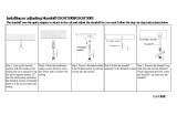
Page 18 40216-1-0120
ADDING NAILING FLANGES AND STANDOFF BRACKETS
1. At the top and bottom of the replace, use pliers to bend
each side standoff 90 degrees away from the cabinet. See
Figure 12.
Figure 12
NOTICE: The nailing anges and standoff brackets that are
supplied with the replace must be used. Locate the nailing
anges and standoff brackets that are shipped inside the
hardware box behind the replace.
2. The holes in the nailing anges allow for different thickness
boards and depths of wall boards. See Figure 13. Install
nailing anges with two 10 x 1/2" screws (each) in pair of
holes closer to the face of the replace. Leave the nailing
anges at until after the replace is lifted into the framing.
See Figures 14 and 15.
5/8” BOARD
1/4” BOARD
½” BOARD
Figure 13
Figure 14 - OPTION 1
Figure 15 - OPTION 2
WARNING
TWO MAN LIFT RULE!
3. Repeat on opposite side.
4. Insert replace into enclosure.
5. Level replace.
6. Bend nailing anges over side frames and attach.
7. Locate the steel standoff brackets inside the hardware box.
See Figure 16.
Figure 16
8. The brackets have a perforation at the bottom of each side.
Bend them at the perforation. See Figure 17.
Figure 17

40216-1-0120 Page 19
ADDING NAILING FLANGES AND STANDOFF BRACKETS
9a. OPTION 1 - Secure the brackets to the replace top with
screws. There are holes located in the top of the replace for
each standoff bracket. The holes closer to the front edge of
the replace are for mounting non-combustible board around
the opening. Finishing OPTION 1. See Figure 18.
FOR USE WITH
NON-COMBUSTIBLE
BOARDS TO
OPENING
FIREPLACE OPENING
TOP OF
FIREPLACE
Figure 18 - OPTION 1
9b. OPTION 2 - Secure the brackets to the replace top with
screws. There are holes located in the top of the replace
for each standoff bracket. The holes back further from the
front edge of the replace are for mounting non-combustible
board to the top of the replace so that tile or stone can
cover the face. Finishing OPTION 2. See Figure 19.
FOR USE WITH
NON-COMBUSTIBLE
BOARDS TO TOP
OF FIREPLACE
FIREPLACE OPENING
TOP OF
FIREPLACE
Figure 19 - OPTION 2
10a.
OPTION 1 - Secure standoff brackets with drywall screws to the
framed opening above the replace as shown in Figure 20.
SCREW INTO
EACH BRACKET
Figure 20 - OPTION 1
10b. OPTION 2 - Secure standoff brackets with drywall screws to
the framed opening above the replace as shown in Figure 21.
SCREW INTO
EACH BRACKET
Figure 21 - OPTION 2

Page 20 40216-1-0120
UTILITY INSTALLATION
Remove barrier screen assembly from replace by lifting up
slightly and pulling out. Set aside. Remove the burner cover by
lifting it up and out. Set aside.
Bring the gas supply through the left or right side of the replace
to connect to the burner. See Figures 22 and 23. Consult the
current National Fuel Gas Code, ANSI Z223.1 CAN/CGA-B149
(.1 or .2) installation code.
CAUTION
Never use plastic pipe. Check to conrm whether the local
codes allow copper or galvanized tubing.
NOTICE: Since some municipalities have additional local codes, it
is always best to consult the local authority and installation code.
The use of the following gas connectors is recommended:
— ANSI Z21.24 Fireplace Connectors of Corrugated Metal
Tubing and Fittings.
— ANSI Z21.45 Assembled Flexible Fireplace Connectors of
Other Than All-Metal Construction
The connectors specied by the National Fuel Gas Code may
be used if acceptable by the authority having jurisdiction.
The Commonwealth of Massachusetts requires that a exible
replace connector cannot exceed three feet in length.
TEE HANDLE
FLEX TUBING
FLARE FITTING
FLEXIBLE GAS LINE CONNECTION
GAS SUPPLY
Figure 22
INSTALLING THE MAIN GAS SHUT-OFF
Each replace should have its own manual gas shut-off.
Locate the manual main gas shut-off in the vicinity of the replace
easily accessible after assembly. Contact the local authorized
installer for installation or relocation when no shutoff exists or the
location is not adequate.
Compounds used on threaded joints of gas piping are resistant
to the action of liqueed petroleum gases. Gas lines must be
checked for leaks by the installer. A leak testing solution or soap
should be used for testing leaks on all exposed connections.
After testing is complete, all solutions should be cleaned off.
On unexposed connections, a pressure test should be made.
Never use an exposed ame to check for leaks. Fireplace must
be disconnected from piping at inlet of control valve and pipe
capped or plugged for pressure test. Never pressure test with
replace connected; control valve will sustain damage.
When using copper or ex connector use only approved
ttings. The replace and its individual shut-off valve must be
disconnected from supply piping system during any pressure
testing of that system at test pressures in excess of 1/2 psig
(3.5kPa). The replace must be isolated from the gas supply
piping system by closing its individual manual shut-off valve
during any pressure testing of the gas supply piping system at
test pressures equal to or less than 1/2 psig (3.5kPa).
TESTING GAS SUPPLY PRESSURE
NOTICE: The gas controls are equipped with a captured screw-
type pressure test point. It is not necessary to provide a 1/8-inch
test point up stream of the control. Bleed gas line before testing
gas pressure. Check for leaks.
Natural Gas will have a manifold pressure of approximately 3.5
inches w.c. at the pressure regulator outlet with the inlet pressure
to the pressure regulator from a minimum of 7.0 inches w.c. for
the purpose of input adjustment to a maximum of 10.5 inches w.c.
Propane Gas will have a manifold pressure approximately 10.0
inches w.c. at the pressure regulator outlet with the inlet pressure
to the pressure regulator from a minimum of 11.0 inches w.c. for
the purpose of input adjustment to a maximum of 13.0 inches w.c.
A test gage connection is located on the gas valve for measuring
gas pressure. The connections are two contained screws inside
the tapered hose slip connections.
GAS PRESSURE (Inches Water Column)
Gas Type Maximum Minimum Manifold
Natural 10.5 7.0 3.5
Propane 13.0 11.0 10.0
MANIFOLD PRESSURE
TEST PORT
OUT
INLET PRESSURE
TEST PORT
IN
Figure 23
WARNING
If one of the procedures results in pressures in excess of
1/2 psig (14 inches w.c.) (3.5 kPa) on the replace gas
valve, it will result in a hazardous condition.
/