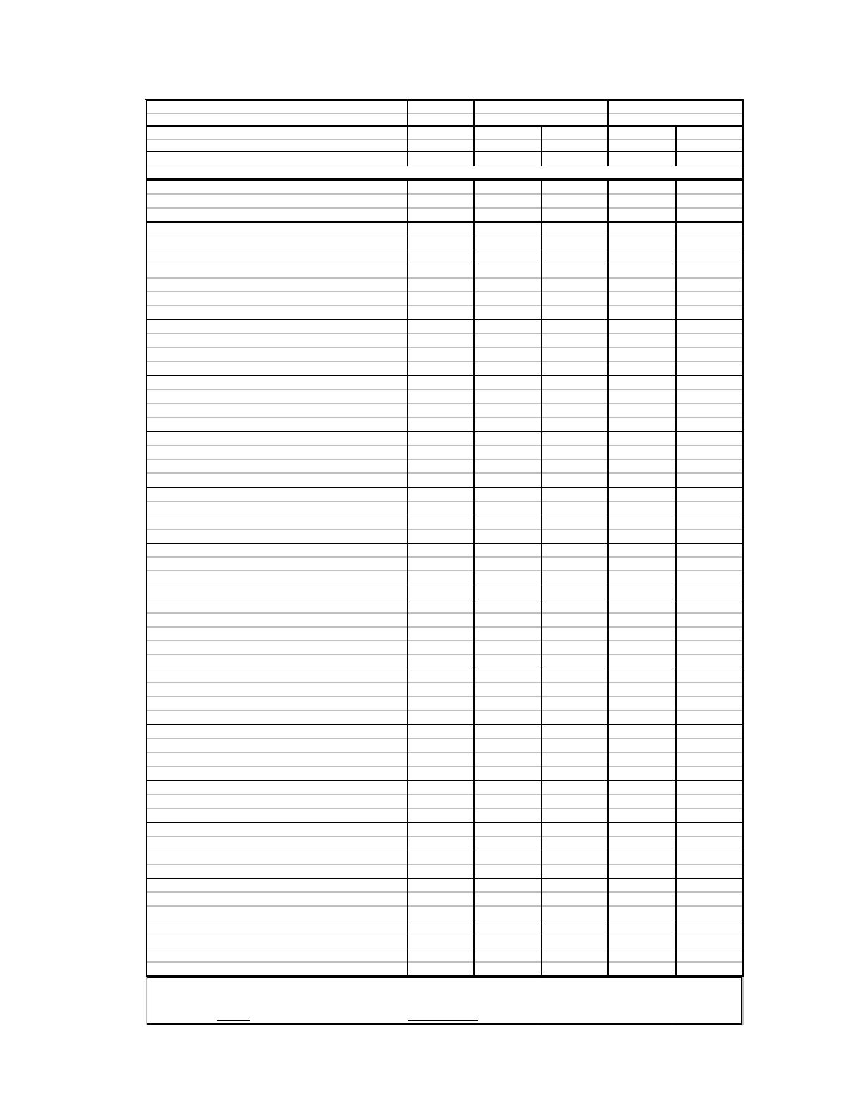
HOW TO PROPERLY ORDER PARTS: In addition to part description and part number, please give model number, serial
number, and type of gas used. This information can be found on the rating plate located in control compartment.
Page 19* Requires 2
REV. 10/2010 / MARCH 2011
NAT. CDV255B CDV335B
M
DEL NUMBER
L.P.
DV
5
B
DV
B
REF. PART LIST PART LIST
P
RT DE
RIPTI
NN
.N
.PRI
N
.PRI
Heat Exchanger Kit, INCLUDES 1 42770 336.00$ 42770 336.00$
Wrapper (Ref. # 2), Right and Left Leg (Ref. # 6 & 7), AND Comb. Air Pan Assembly w/Gaskets (Ref. # 63)
Cabinet 3 42755 222.90$ 42755 222.90$
Leg, Right 6 43495 11.30$ 43495 11.30$
Leg, Left 7 43494 11.30$ 43494 11.30$
Front Heat Shield Assembly 9 43481 27.70$ 43481 27.70$
Bottom Heat Shield Assembly 10 43473 12.40$ 43473 12.40$
Vent Cap with Spacer Plate 11 & 12 43145 130.20$ 43145 130.20$
Air Intake Tube Assy. (5-9" Wall) 6-3/4"Dia. 15 43200 17.90$ 43200 17.90$
Air Intake Tube Assy. (9-15" Wall) 16 43810 25.50$ 43810 25.50$
Air Intake Tube Assy. (15-24" Wall) 58 43705 27.60$ N/A N/A
Air Intake Tube Gasket - 8-1/2" Circle 17 70061 4.10$ 70061 4.10$
Vent Exhaust Tube Assy. (5-9" Wall) 4-3/16" dia. 18 43530 21.20$ 43539 15.50$
Vent Exhaust Tube Assy. (9-15" Wall) 19 43820 24.00$ 43828 21.40$
Vent Exhaust Tube Assy. (15-24" Wall) 59 43717 27.40$ N/A N/A
Vent Exhaust Tube Gasket (Requires 4) 5-3/8" Circle 20 70062 2.30$ 70062 2.30$
Wall Thimble (5-9" Wall) 21 43552 16.50$ 43552 16.50$
Wall Thimble Extension (5-9" Wall) 22 43236 5.40$ 43236 5.40$
Wall Thimble Extension (9-15" Wall) 23 43835 11.80$ 43835 11.80$
Wall Thimble Extension (15-24" Wall) 60 43730 17.30$ N/A N/A
Wall Thimble Gasket - 11x11" 24 70066 1.90$ 70066 1.90$
Burner Access Door 25 43247 9.20$ 43247 9.20$
Burner Access Door Gasket - 5-1/2x11-3/8" 26 70060 10.90$ 70060 10.90$
Burner 27 70006 61.20$ 70006 61.20$
Manifold 28 70032 21.70$ 70032 21.70$
Manifold Gasket - 2x2" 29 70065 1.50$ 70065 1.50$
Main Burner Orifice (Nat. Gas) 30 70048 4.00$ 70047 4.00$
Main Burner Orifice (L.P. Gas) 30 70039 4.00$ 70049 4.00$
Sight Glass Assembly 31 43252 7.60$ 43252 7.60$
Sight Glass Cover 32 43258 1.80$ 43258 1.80$
Sight Glass/Pilot Burner, Gasket - 3-1/2x2-3/4" 33 70064 1.50$ 70064 1.50$
Pilot Burner Q350A1529 (Nat. Gas) 34 70007 9.20$ 70007 9.20$
Pilot Burner Q350A1537 (L.P. Gas) 34 70008 9.20$ 70008 9.20$
Electrode 35 70052 9.10$ 70052 9.10$
Electrode Wire 36 70051 3.20$ 70051 3.20$
Piezo Sparker 37 80016 6.70
$ 80016 6.70$
Piezo Sparker Bracket 38 43263 3.20$ 43263 3.20$
Valve, MV,
Robertshaw
7000MVRLC-Nat. Gas 39 70090 158.70$ 70090 158.70$
Valve, MV,
Robertshaw
7000MVRLC-L.P. Gas 39 70091 168.80$ 70091 168.80$
Valve, MV,
Dexen
6003, Natural Gas 39 84085 158.70$ 84085 158.70$
Valve, MV,
Dexen
6003LP, L.P. Gas 39 84086 168.80$ 84086 168.80$
Pilot Generator, TP75 Millivolt 40 70098 37.70$ 70098 37.70$
Pilot Tubing w/fittings 41 70012 7.70$ 70012 7.70$
Thermostat, Millivolt 42 74592 23.40$ 74592 23.40$
Thermostat Wire N/A 74518 1.60$ 74518 1.60$
Insulated Staples N/A 74209 1.50$ 74209 1.50$
Gasket, Air Pan Top & Bottom (15-1/4x1) 61 *70074 1.50$ *70074 1.50$
Gasket, Air Pan Sides (25x1) 62 *70073 1.50$ *70073 1.50$
90 Degree Elbow 56 70352 12.50$ 70352 12.50$
Vent Terminal Shield N/A 34950 71.00$ 34950 71.00$
Blower Housing w/Motor & Blower 46 70201 124.50$ 70201 124.50$
Junction Box 47 43610 4.90$ 43610 4.90$
Junction Box Cover 48 43620 6.00$ 43620 6.00$
Fan Switch 120 degree 50 70110 7.40$ 70110 7.40$
Cord Set 51 80202 4.90$ 80202 4.90$
Cover Plate N/A 43078 2.80$ 43078 2.80$
Blower Screen N/A 43635 24.50$ 43635 24.50$
Left Air Intake Baffle N/A 43528 4.50$ 43528 4.50$
Right Air Intake Baffle N/A 43526 3.80$ 43526 3.80$
ATTN: CONTRACTORS and SERVICE TECHNICIANS
, we only sell parts through our wholesalers, but the prices
listed above are for your convenience. For prompt parts service, contact the wholesaler from which you purchased your
Cozy heater. NOTE
: Parts & schematic drawings on current models are shown at
www.cozyheaters.com
.