
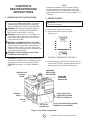
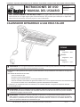
E1 Installation instructions and Owner’s Manual
GAS FIRED INFRA-RED WORKSHOP HEATER
MR. HEATER, INC., 4560 W. 160TH ST., CLEVELAND, OHIO 44135 · 800-251-0001
WARNING: If the information in this manual is not followed exactly, a re or explosion may result causing
property damage, personal injury, or loss of life.
- Do not store or use gasoline or other ammable vapors and liquids in the vicinity of this or any other appliance.
- WHAT TO DO IF YOU SMELL GAS
•Shut off gas supply
• Do not try to light any appliance
•Do not touch an electrical switch; do not use any phone in your building.
•Immediately call your gas supplier from a neighbor’s phone. Follow the gas supplier’s instructions.
•If you cannot reach your gas supplier, call the re department.
- Installation and service must be performed by a qualied installer, service agency, or the gas supplier.
WARNING: This is an unvented gas-red heater. It uses air (oxygen) from the room in which it is installed.
Provisions for adequate combustion and ventilation air must be provided. Refer to Fresh Air for Combustion
and Ventilation section on page 6 of this manual.
WARNING: Improper installation, adjustment, alteration, service or maintenance can cause property damage,
injury or death. Read the installation, operation, and maintenance instructions thoroughly before installing or
servicing this equipment. For assistance or additional information consult a qualied installer, service agency,
or gas supplier.
04/15 18672
Installer: Leave this manual with the appliance. Consumer: Retain this manual for future reference.
MH25NG
MH25LP
LANGUAGES
ENGLISH
Pages E1 — E16
SPANISH
Pages S1 — S16
FRENCH
Pages F1 — F16
Operating instructiOns
and Owner’s Manual
read instructiOns careFullY: Read and follow all instructions. Place instructions in a safe
place for future reference. Do not allow anyone who has not read these instructions to assemble,
light, adjust or operate the heater.
Model #

E2 Installation instructions and Owner’s Manual
WARNINGS
WARNING: Improper installation, adjustment,
alteration, service or maintenance can cause
property damage, injury or death. Read the
installation, operation, and maintenance instruc-
tions thoroughly before installing or servicing this
equipment. For assistance or additional informa-
tion consult a qualied installer, service agency,
or gas supplier.
WARNING: When used without fresh air, heater
may give off CARBON MONOXIDE, an odorless
poisonous gas. OPEN WINDOW AN INCH OR
TWO FOR FRESH AIR WHEN USING HEATER.
WARNING: This heater is equipped with a PILOT
LIGHT SAFETY SYSTEM. DO NOT TAMPER
WITH PILOT LIGHT SAFETY SYSTEM.
WARNING: If heater shuts off, do not relight until
you provide fresh air. If heater keeps shutting off,
have it serviced. Keep burner and control clean.
Open door for 5 minutes.
Maintain clearances as shown in Figure 2 or on
heater nameplate.
• DO NOT USE MATCH OR OTHER FLAME
FOR LEAK TESTING.
• DO NOT EXCEED 1/2 PSI INLET PRES-
SURE TO HEATER.
DANGER: Carbon monoxide poisoning may lead to
death.
Carbon Monoxide Poisoning:
Early signs of carbon monoxide poisoning resemble the
u, with headaches, dizziness, or nausea. If you have
these signs, the heater may not be working properly.
Get fresh air at once! Have heater serviced. Some
people are more affected by carbon monoxide than oth-
ers. These include pregnant women, persons with heart
or lung disease or anemia, those under the inuence of
alcohol, and those at high altitudes.
CAUTION
• Never connect gas valve or thermostat to line volt-
age or a transformer.
• If the infra-red color of the grid becomes dull when
the building furnace is operating, consult gas sup-
plier on correct gas supply piping sizes.
• This heater is for indoor installation only!
NOTE
Gasket binder material used in this heater assembly will
temporarily emit an odor and/or vapor. This condition
will clear up in approximately 20 minutes and thereafter
will not reoccur. Refer to Chapter 2 for ventilation.
TABLE OF CONTENTS
Chapter Title Page
I Introduction ............................................. E3
II Heater Installation .................................. E5
III Heater Operating Instructions ................ E10
IV Operator Maintenance Instructions ........ E12
V Replacement Parts List .......................... E15
warning:
The State of California requires the following
warning:
COMBUSTION BY-PRODUCTS PRODUCED WHEN US-
ING THIS PRODUCT CONTAIN CARBON MONOXIDE,
A CHEMICAL KNOWN TO THE STATE OF CALIFORNIA
TO CAUSE CANCER AND BIRTH DEFECTS (OR OTHER
REPRODUCTIVE HARM).
THIS PRODUCT CONTAINS CHEMICALS KNOWN TO
THE STATE OF CALIFORNIA TO CAUSE CANCER AND
BIRTH DEFECTS OR OTHER REPRODUCTIVE HARM.
CANADA ONLY:
Per CAN/CGA-B149.1.2 gas code, this heater can not
be installed in residential garages in Canada

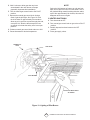
E3 Installation instructions and Owner’s Manual
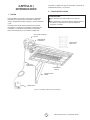
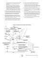
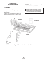
GAS CONTROL
VALVE
POWERPILE
GENERATOR EXHAUST
VENT
BASIC HEATER
WALL MOUNTING
BRACKET
THERMOSTAT
CABLE
THERMOSTAT
CHAPTER I
INTRODUCTION
1. EQUIPMENT
This heater is the consumer version of our highly suc-
cessful, thoroughly tested, gas red, infrared, industrial
utility heater.
This heater does not require an external electrical
source for operation.
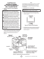
The major components of the heater and a typical
installation are identied in Figure 1. The basic heater
Figure 1. Heater Major Components
consists of the complete burner assembly, ue deec-
tor, grid, reector assembly and face guard.
2. PURPOSE OF EQUIPMENT
WARNINGS
This heater is for indoor installation only.
This heater is designed to heat indoor areas. Do not
use for inhabited or small, enclosed areas.

E4 Installation instructions and Owner’s Manual
3. GENERAL INFORMATION
• Your heater comes fully assembled and is tested
at the factory with the appropriate type of gas
and at the input pressures stated on the name-
plate.
• Upon receipt and prior to attempting installation,
be sure to inspect the heater and its packaging
for damage and/or missing components. If dam-
age is found or missing components are sus-
pected, contact your dealer. See Chapter 5 for a
complete listing of items required for the safe and
efcient installation and use of this heater.
• Never attempt to operate the heater using a
fuel other than that specically identied on the
nameplate.
• The installation of the heater must conform with
all local building codes or, in absence of gov-
erning local codes, with the National Fuel Gas
Code, ANSI Z223.1 (NFPA 54). This code can
be obtained from either the: Canadian Standards
Association, 8501 East Pleasant Valley Road,
Cleveland, OH 44131; or, NFPA, Battery March
Park, Quincy, MA 02269.
• Canadian installations must comply with CAN/
CGA-B149.1.2 gas code which can be purchased
from Canadian Gas Association, 55 Scarsdale
Road, Don Mills, Ontario M3B 2R3.
• Contact factory when appliance is to be installed
at high altitudes. Factory can supply high altitude
conversion kit with instructions and data plate.
• A plugged 1/8” N.P.T. Test Gage Connection is
provided on the heater gas control.
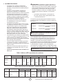
•See Tables 1 and 2 for heater specications:
WARNING: Improper installation, adjustment, al-
teration, service or maintenance can cause property
damage, injury or death. Read the installation, opera-
tion, and maintenance instructions thoroughly before
installing or servicing this equipment. For assistance
or additional information consult a qualied installer,
service agency, or gas supplier.
•For additional information contact Mr. Heater Toll-
Free 800-251-0001—www.mrheater.com
The following extra NFPA Manuals are helpful when
installing this heater in a location not anticipated in this
manual:
Number Related Subject
NFPA 88 Clearances to Combustible Surfaces
NFPA 409 Clearances to Combustible Surfaces
DO NOT EXCEED 1/2 PSI INLET PRESSURE TO HEATER
Provide adequate clearance to combustibles per Table 3
at control end of heater for servicing and minimum on top
and sides for ventilation and combustion air supply.
A minimum clearance of 8’ above oor for public garages
in accordance with NFPA No. 88 most recent edition, or
Figure 1; whichever is larger.
Canadian installations in public garages must comply with
CGA 149B.1.9 most recent edition.
WARNING: Maintain clearances as shown in Figure 2
or on heater nameplate.
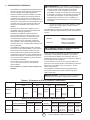
Table 1. BTU Ratings and Supply Pressures
MODEL BTU/HR. RATING GAS SUPPLY PRESSURE (W.C.) ORIFICE
NO. GAS MIN. MAX. MANIFOLD SIZE
NATURAL PROPANE NAT. L.P. NAT. L.P. NAT. L.P. NAT. L.P.
MH25NG 25,000 — 7.0” — 14” — 6” — 45 —
MH25LP — 22,000 — 11” — 14” — 10” — 55
Table 2. Heater Dimensions and Orice Sizes
MODEL OPERATING ORIFICE SIZE INPUT SIZE
NO. PRESSURE BURNER PILOT BTU/H WIDTH LENGTH HEIGHT WEIGHT
MH25NG 6.0”w.c. 45 .018 25.000 12-1/4” 29-3/4” 7” 20 lb.
MH25LP 10”w.c. 55 .011 22,000 12-1/4” 29-3/4” 7” 20 lb.

E5 Installation instructions and Owner’s Manual
CHAPTER II
HEATER INSTALLATION
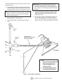
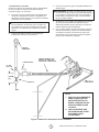
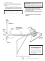
1. GENERAL INSTALLATION INFORMATION
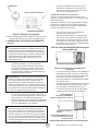
AND REQUIREMENTS
• The required minimum clearances to combustible
surfaces are illustrated in Figure 2 and Table 3.
As shown on Figure 2, the front of the heater is
installed at the minimum required clearance to
combustible surfaces and toward open space,
and then the other sides must have a minimum
clearance of 16 inches to combustible surfaces.
EXHAUST
VENT CEILING
14”
MINIMUM
16”
MINIMUM
48”
MINIMUM
OPEN
WORKSHOP DOOR
HEATER
WALL BRACK-
ET
16”
MINIMUM
14-1/2”
FLOOR LINE
30
1. ONLY FLUE SIDE OF HEATER CAN
BE ELEVATED (30o).
2. HEATER SIDE REFLECTOR MUST
BE HORIZONTAL.
NOTE:
Figure 2. Installation Clearances to Combustible Surfaces
Table 3. Installation, Ventilation and Mounting Information
BTU/HR. RATING NORMAL
MODEL GAS MOUNTING CLEARANCES TO COMBUSTIBLE SURFACES
NO. NAT. L.P. POSITION TOP SIDES BACK BELOW
MH25NG 25,000 — 30o 14” 16” 16” 48”
MH25LP — 22,000 30o 14” 16” 16” 48”
The clearances to combustibles represent a surface
temperature of 90°F (32°C) above room temperature.
Building materials with low heat tolerance may be
subject to degradation at lower temperatures. It is the
installer’s responsibility.
CLEARANCES

E6 Installation instructions and Owner’s Manual
•This heater may be mounted on any wall;
however, it is recommended that the heater be
mounted in the middle of the wall opposite any
overhead doors.
•When selecting installation locations for this
heater ensure that the opening of any exterior
or interior doors or windows will not violate
minimum clearances or contact any heater
components.
•If an overhead door is installed in the build-
ing, verify that the heater is not installed in
such a way as to interfere with door operation
and verify that the door in its open position
will not reduce clearances below the minimum
requirements. Never mount the heater in such
a way that would position the heater above an
opened overhead door.
Unrestricted air ow during heater operation is essen-
tial to prevent the area above the installed heater from
overheating. In most cases the infiltration around your
uninsulated entry doors and windows will provide
enough air flow for efficient heater operation. If your
workshop/utility building is tightly insulated (including
windows, doors, openings, etc.) the following
ventilating methods must be followed:
•A single exhaust vent is supplied with your
heater for your convenience. This vent must
be located above the heater (preferably at the
highest point in the building interior) and it must
vent to the exterior of the building. An addition-
al vent is available from the factory for those
having a nished workshop or utility building.
•An intake vent, or equivalent, from the exterior
of the building and having an effective area of
75 square inches must be located below the
heater (preferably within 2 feet of the building’s
oor).
•Openings equivalent to intake vent would be:
partially open doors and partially open win-
dows.
•Openings of this size (5 inch by 13 inch, or 3
inch by 25 inch) will prevent dangerous heat
buildup above the heater.
Ensure that no gas lines or electrical wiring or conduits
will interfere with mounting of the heater to the wall.
Depending on local codes and requirements and the
installer’s skill level, the sizing and installation of gas
lines required to supply the heater may require the
assistance of a professional. If in doubt as to these
requirements, discuss the requirements of this manual
with the dealer from whom the heater was purchased
and your gas supplier, or call our customer service
department at 1-800-251-0001.
The selection of the thermostat mounting location is
critical to efcient and effective heater operation.
•The thermostat should be mounted about 5 feet
above the oor where air can circulate freely
around it.
•The thermostat should not be mounted directly
to a cold exterior wall without an insulated
mounting block.
•The thermostat should not be mounted in direct
drafts.
•The thermostat should not be mounted directly
below the installed the heater.
•The thermostat should not be installed at a
distance that is farther from the heater than the
length of the thermostat cable.
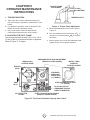
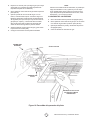
2. HEATER MOUNTING INSTRUCTIONS
After selecting the heater installation location and the
thermostat location and after verifying and ensuring that
all of the above placement requirements are fullled,
mount the heater as follows:
A. Determine how you wish to install the vent based
on the construction of the building and your
personal preference. (i.e., do you wish the anged
(nished) side on the interior or the exterior of the
building or do you want two vents so that both
exterior and interior will be nished?) If needed,
order an additional vent from the factory. Our
address and toll free phone number are on the rear
cover of this manual. Install the vent as follows:
1. See Figure 3 for dimensions and information on
the vent.
2. Select a place as high above the heater as
possible in accordance with the above require-
ments and ensure that the vent or vents will
not contact or interfere with existing building
systems (i.e., ducts, wiring, plumbing, etc.)
3. Place the unnished side of the vent against
the wall in its elected location and trace its
dimensions on the wall with a pencil or other
suitable marker.
4. Cut or otherwise open a hole in the wall, or
walls for nished buildings, having the dimen-
sions of the unnished side of the vent.
5. Install the vent or vents as desired and retain
HEATER VENTILATION

E7 Installation instructions and Owner’s Manual
with 4 suitable fasteners through the predrilled
holes in vent ange.
B. Prepare to install the heater wall mounting bracket
as follows:
1. If the wall mounting bracket is to be attached to
a stud and wallboard wall, refer to Figure 3 for
dimensions, locate a stud, and drill two 1/8” pi-
lot holes into the stud centerline. Use template
for simplied installation.
2. If the wall mounting bracket is to be attached
to a brick or masonry wall, refer to Figure 3 for
dimensions. Obtain two 1/4 inch (inside diam-
eter) expansion anchors and determine the
correct drill size to be used with them. Drill the
appropriate size holes in the brick or masonry
to accept the anchors.
C. Place the wall mounting bracket on the wall and
align the two through holes on the bracket with
the pilot holes or anchors. Install 1/4 inch by 2-1/2
inch lag screws through the bracket into the stud or
anchors. Tighten securely.
D. Locate heater mounting clip on back of heater and
select the 1/4” – 20 by 3/4” hex head bolt and 1/4” -
20 hex nut.
CEILING
HEATER
24” MIN
9”
58”
FLOOR
THERMOSTAT (SEE INSTRUCTIONS
INCLUDED WITH THERMOSTAT
#6 X 1” SHEET METAL SCREWS
(2 REQUIRED - INCLUDED WITH
THERMOSTAT)
THERMOSTAT CABLE
(SEE FIGURE 4)
1/4” X 2-1/2” LONG
LAG SCREWS
(2 REQUIRED)
GAS
CONTROL
VALVE
1/2” NPT GAS INLET
(DO NOT EXCEED 1/2 PSI)
HEATER RE-
FLECTOR
FLUE DE-
FLECTOR
1/4”-20x3/4” HEX-
HEAD BOLT
MOUNTING
CLIP
1/4”-20
HEX NUT
HEATER WALL
MOUNTING
BRACKET
PREDRILLED
HOLES
FINISHED
SIDE
UNFINISHED
SIDE
FLANGE
E. Position the heater as shown in Figure 3 and slide
the heater mounting clip over the bracket and install
the bolt through the clip and bracket.
F. Thread the hex nut onto the bolt and tighten
securely.
G. Ensure that the selected thermostat location
meets all of the above requirements. Refer to
the instructions that come with the thermostat for
additional grounding information and mounting
instruction.
H. If the wall is of stud and wallboard construction,
then use the #6 by 1 inch sheet metal screws,
included with the thermostat, and mount the
thermostat in the selected location.
I. If wall is brick or masonry, the appropriate anchors
must be obtained to accommodate thermostat
mounting screws. Use the back plate of the
thermostat as a template to mark the hole locations,
drill appropriate size anchor holes, install the
anchors, securely attach the thermostat using the
mounting screws.
J. Connect thermostat wires to gas valve as shown in
Figure 4.
Figure 3. Heater Mounting Information

E8 Installation instructions and Owner’s Manual
LEAVE 2 THREADS BARE
USE MODERATE AMOUNT OF PIPE DOPE
3/4” MAXIMUM
THREAD LENGTH
1/2” BLACK PIPE
GAS VALVE BODY
1/2” MAXIMUM
DEPTH OF IN-
SERTS INTO GAS
VALVE
Refer to National Electrical Code NFPA70-1993 and
for Canadian installations to current CODE C22.1-
3. CONNECTING HEATER TO GAS SUPPLY
WARNING: Depending on local codes and require-
ments and the installer’s skill level, the sizing and
installation of gas lines required to safely and efciently
supply the heater may require the assistance of a pro-
fessional. If in doubt as to these requirements, discuss
the requirements of this manual with the dealer from
whom the heater was purchased and your gas supplier.
3.1 Gas Supply Requirements
•See Tables 1 and 2 for gas supply minimum, maxi-
mum, operating, and manifold pressures for both
heater models. Pressures are provided in inches of
W.C. (water column). Also, see heater rating plates
located on the heater.
WARNING: Model MH25NG is designed to burn
natural gas and it comes equipped with a regulator.
The regulator is built into the gas valve. The maximum
inlet pressure to this regulator is 1/2 psi (14 in. W.C.) If
gas line pressure exceeds 1/2 psi, then an additional
regulator must be installed before the heater/regulator
to step down the pressure to a maximum of 1/2 psi.
•Most non-commercial natural gas services provide
a line pressure of 4 oz. (6.9 in. W.C.). If in doubt
consult your natural gas supplier.
•To ensure the best performance from your natural
gas heater make sure the supply manifold pres-
sure is at least 6” W.C.
WARNING: Model MH25LP is designed to burn
liqueed petroleum (LP) gas and it comes equipped
with a regulator. The regulator is built into the gas
valve. The maximum inlet pressure to this regulator
is 1/2 psi (14 in. W.C.). If gas line pressure exceeds
1/2 psi, then an additional regulator must be installed
before the heater/regulator to step down the pressure
to a maximum of 1/2 psi.
• To ensure the best performance from your LP gas
heater, make sure the supply manifold pres-
sure is at least 1/2 psi (14 in W.P.).
3.2 Piping Requirements
All piping installed must comply with local codes and
ordinances or with National Fuel Gas Code,
ANSI Z223.1 (NFPA 54), whichever takes precedence.
When installing piping, the following requirements
must be taken into consideration: Canadian installa-
tions must comply with the B149.1.2 Gas Code.
•Use new properly reamed black pipe free from
chips.
•Apply a good quality pipe compound to all
male threads as shown in Figure 5 prior to as-
sembly. If LP gas is the fuel, ensure that pipe
compound is resistant to LP gas. Do not use
Teon™ tape.
Figure 5. Pipe Compound Application
•Male threads on pipe to be installed into gas
valve shall meet the requirements of Figure 6.
Threads longer than those shown in the gure
may cause gas valve distortion and malfunc-
tion.
•A sediment trap meeting the typical require-
ments of Figure 7 shall be installed in the line
to the gas valve.
•A dedicated shutoff valve for the heater must
be installed in the gas supply line.
3.3 Piping Installation
While ensuring that all of the above gas supply re-
THERMOSTAT
POWERPILE GAS VALVE
POWERPILE GENERATOR
Figure 4. Connection Diagram
Figure 6. Gas Valve Connection Requirements

E9 Installation instructions and Owner’s Manual
quirements and piping requirements are fullled, install
piping as follows:
A. In accordance with the above piping requirements,
assemble piping, sediment trap, shutoff valve, and
necessary ttings. Tighten all components securely.
WARNING: Failure to ensure that male threads on
pipe to be installed into gas valve meet the require-
ments of Figure 6 may cause gas valve damage,
distortion and malfunction.
B. Install a threaded nipple, prepared in accordance
with paragraph 3.2 into gas valve.
C. Connect gas piping to nipple installed in the gas
valve.
SUPPLY
LINE
SHUTOFF
VALVE
1/2”
TEE
3”
CAP
NIPPLE HEATER
RIGID PIPE WITH
UNION OR A FLEXIBLE CON-
NECTOR TO HEATER
Figure 7. Typical Piping Installation
NOTE:
1. ONLY USE A PIPE COMPOUND
WHICH IS RESISTANT TO
LIQUIFIED GASES ON LP
INSTALLATIONS.
2. FITTINGS SHOWN ARE NOT
INCLUDED WITH HEATER.
WARNING: When testing gas piping use only a
soap and water solution. Do not use a match or
other ame for leak testing. If during leakage check
gas is smelled, turn off the gas supply and ventilate
building.
D. Ensure the building is properly ventilated. Without
lighting the pilot light of the heater, open the gas
supply valve and pressurize the piping up to the
heater’s gas valve.
E. Using a brush, apply a soap and water solution to
all connections and look for bubbles indicating a
leak. If a leak is detected, turn off gas supply and
tighten connections. Retest and tighten connections

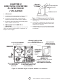
E10 Installation instructions and Owner’s Manual
MANUAL GAS
CONTROL
KNOB
PILOTSTAT
POWER UNIT
PRESSURE
REGULATOR
ADJUSTMENT
STANDARD
PRESSURE
REGULATOR
PILOT GAS OUTLET
(PRESSURE TAPPING
DIRECTLY BENEATH)
PILOT FLOW ADJUSTING SCREW
(BENEATH COVER SCREW)
WRENCH
BOSS
GAS IN-
LET
Figure 9. Gas Valve Components
2. HEATER STARTUP
WARNING: During heater startup ensure that build-
ing is well ventilated.
A. Open the gas supply valve or valves.
B. Set the thermostat to the OFF position.
See Figure 8.
C. If the manual gas control knob on the gas valve is
not in the OFF position, partially depress the knob
and rotate to the OFF position. See Figure 9.
CHAPTER III
HEATER OPERATING
INSTRUCTIONS
1. OPERATING SAFETY INSTRUCTIONS
WARNING: When used without fresh air, heater
may give off CARBON MONOXIDE, an odorless
poisonous gas. OPEN WINDOW AN INCH OR
TWO FOR FRESH AIR WHEN USING HEATER.
WARNING: This heater is equipped with a PILOT
LIGHT SAFETY SYSTEM. DO NOT TAMPER
WITH PILOT LIGHT SAFETY SYSTEM.
WARNING: If heater shuts off, do not relight until
you provide fresh air. Open door for 5 minutes. If
heater keeps shutting off, have it serviced. Keep
burner and control clean.
WARNING: CARBON MONOXIDE POISONING
MAY LEAD TO DEATH. Early signs of carbon mon-
oxide poisoning resemble the u with headache,
dizziness and/or nausea. If you have these signs,
heater may not be working properly. Get fresh air at
once! Have heater serviced.
WARNING: DO NOT USE MATCH OR OTHER
FLAME FOR LEAK TESTING.
CAUTION: If the infra-red color of the grid becomes
dull when the building furnace is operating, consult
gas supplier on correct gas supply piping sizes.
CAUTION: This heater is for indoor installation
only!
NOTE
Gasket binder material used in this heater assem-
bly will temporarily emit an odor and/or vapor. This
condition will clear up in approximately 20 minutes
and thereafter will not reoccur. Refer to Chapter 2 for
ventilation.
FIGURE 8. THERMOSTAT CONTROLS

E11 Installation instructions and Owner’s Manual
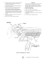
PILOT BURNER
LIGHT PILOT WITH MATCH
AS SHOWN
GAS VALVE
DEPRESS TO
LIGHT
D. Wait 5 minutes to allow gas that may have
accumulated in the main burner to escape
(especially important after installation).
E. Turn the manual gas control knob to the PILOT
position.
F. Depress the manual gas control knob. Using a
match, light the pilot light. See Figure 10. Hold
the knob down for approximately 30 seconds to
allow any air in gas lines to pass through pilot and,
once pilot is lit, allow the thermocouple to heat
up enough to activate the safety valve in an open
position.
G. Release manual gas control knob and turn to ON.
H. Reset thermostat to desired temperature.
NOTE
During the initial startup of heater, an odor and, per-
haps, some vapor will come from the heater. This is
the gasket binding material emitting this odor and/or
vapor. After approximately 20 minutes, this odor will
disappear and not occur again.
3. HEATER SHUTDOWN
A. Turn thermostat to OFF.
B. Turn manual gas control knob on gas valve to PILOT
position.
C. Partially depress knob and rotate to the OFF
position.
D. Close gas supply valves.
Figure 10. Lighting of Pilot Burner

E12 Installation instructions and Owner’s Manual
CHAPTER IV
OPERATOR MAINTENANCE
INSTRUCTIONS
1. TROUBLESHOOTING
A. Table 4 lists the common malfunctions which you
may nd during the operation or maintenance of your
heater.
B. For additional information, refer to Honeywell Field
Bulletin enclosed in the heater carton.
C. In the event results cannot be obtained after
performing all listed solutions, call the factory.
2. ADJUSTING THE PILOT FLAME
The pilot ame should envelop 3/8 to 1/2 in. (10 to
13 mm) of the tip of the thermocouple or generator.
Refer to Figure 11. To adjust:
MANUAL GAS
CONTROL KNOB
WRENCH
BOSS
GAS
INLET
PILOTSTAT POW-
ER UNIT
PRESSURE REGULATOR ADJUSTMENT
(BENEATH COVER SCREW)
PILOT FLOW ADJUSTING SCREW
(BENEATH COVER SCREW)
INSTALL LONG
SCREW IN
OUTSIDE CORNER
PILOT GAS OUTLET
(PRESSURE TAPPING
DIRECTLY BENEATH)
STANDARD
PRESSURE
REGULATOR
(“A” MODEL)
STEP OPENING REGULATOR
(“C” MODEL)
Figure 12. Top View of Standard Capacity Gas Control
3/8 TO 1/2 INCH
(10-13 MILLIMETERS)
THERMOCOUPLE
PROPER FLAME
ADJUSTMENT
Figure 11. Proper Flame Adjustment
A. Remove pilot adjustment cover screw. Refer to
Figure 12.
B. Turn inner adjustment screw clockwise to
decrease or counterclockwise to increase
pilot ame.
C. Always replace cover screw after adjustment and
tighten rmly to ensure proper operation.

E13 Installation instructions and Owner’s Manual
Table 4. Trouble Shooting Chart
Below in chart form are various symptoms of a malfunctioning system, possible defects that will cause these symp-
toms and suggested corrective measures. The chart assumes that the proper gas pressure is available to the heater
and that the lighting procedure is as stated on the plate attached to the heater.
SYMPTOMS CAUSES SOLUTIONS
burner light off very slow partially block pilot orice replace
pilot out of adjustment re-adjust pilot
burner light off very slow infra-red partially blocked burner orice replace
color stays dull
burner ash back low gas pressure call your gas supplier
(roaring noise during operation and ceramic grid surface will be
dark) damaged burner replace
ceramic grid or burner sooting up rst check for damaged burner replace if damaged
(when new or after cleaning) orice
if burner orice is not damaged replace
then check for damaged manifold
pilot cannot be ignited blocked pilot orice replace
gas cock not in position gas cock knob must be
turned to pilot and held
depressed
pilot gas ow adjustment open and adjust
screw may be closed (see Figure 12)
pilot lights but goes out defective thermocouple replace
defective control replace
pilot stays lit but main burner loose wire or improperly wired tighten connections, check
will not light wiring diagram
defective control replace
blocked burner orice clean orice or replace
failure to ignite main gas off open manual valves
air in gas line bleed gas line
loose wire connections tighten wire connections
dirty wire connections clean terminals and secure
terminals
3. REPLACING THE GAS VALVE UNIT
A. Remove the two gas valve unit wires at the gas
control valve labeled “PP”.
B. Unscrew gas valve from gas piping.
C. Reconnect gas valve and unit wires to terminals
“PP”. Be sure to leave thermostat wire on one
terminal.
4. FREQUENCY OF OPERATOR CHECKS
Intermittent use. Appliances that are used seasonally
should be checked before shutdown and again before
the next use.
Dusty, wet or corrosive environment. Since these
environments can cause the gas control to deteriorate
more rapidly, the system should be checked more often.
The gas control should be replaced if:
A. It does not perform properly on checkout or trouble
shooting.
B. The gas control knob Is hard to turn or push down,
or it fails to pop back up when released.

E14 Installation instructions and Owner’s Manual
IF SERVICE IS REQUIRED
PLEASE DO NOT RETURN THIS APPLIANCE TO YOUR STORE
For information regarding service, please call our Toll-Free Number:
1-800-251-0001.
Our office hours are 8:00 AM – 5:00 PM, Eastern Time Zone
Monday through Friday
Please include the model number, date of purchase, and description of
problem in all communication.

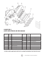
E15 Installation instructions and Owner’s Manual
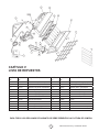
7
6
5
15
4
14
13
10
17
16
22
21
8
20
11 12
13
19 18
2
9
23
ITEM NO. STOCK NO. DESCRIPTION ITEM NO. STOCK NO. DESCRIPTION
1 02529A Burner Assembly Complete 12 05455 Orice-Burner-Propane Gas
2 00377A Reector Assembly 13 05576 Orice-Pilot-Natural Gas
3 01357 Flue Deector 14 05573 Orice-Pilot-Propane Gas
4 16451 Pilot Tube 15 10358 Thermostat Cable
5 00024 Gas Valve-Natural Gas 16 11406 Pilot Burner N/G
6 00025 Gas Valve-Propane Gas 17 11405 Pilot Burner L/P
7 10367 Thermostat 18 04435A Grid Replacement
8 14405 Wall Mounting Bracket 19 12369 Gasket
9 04432 Face Guard 20 05354 Jamb Nut
10 09360 Thermocouple/Generator 21 05351 Connector
11 05445 Orice-Burner-Natural Gas 22 98593 3/8” Close Nipple
23 19014 Intake Louver
ALL WARRANTY CLAIMS REQUIRE PROOF OF PURCHASE
CHAPTER V
REPLACEMENT PARTS LIST

E16
warning:
USE ONLY MANUFACTURER’S REPLACEMENT PARTS. USE OF ANY OTHER PARTS
COULD CAUSE INJURY OR DEATH. REPLACEMENT PARTS ARE ONLY AVAILABLE
DIRECT FROM THE FACTORY AND MUST BE INSTALLED BY A QUALIFIED SERVICE
AGENCY.
FOr inFOrMatiOn regarding serVice Or parts:
Contact your local heating service technician or dealer.
FOr additiOnal inFOrMatiOn:
Please call Toll-Free 800-251-0001—www.mrheater.com
Our office hours are 8:00 AM — 5:00 PM, EST, Monday through Friday.
Please have the model number, serial number and date of purchase ready.
liMited warrantY
The company warrants this product to be free from imperfections in material or
workmanship, under normal and proper use in accordance with instructions of The Company,
for a period of one year from the date of delivery to the buyer. The Company, at its option,
will repair or replace products returned by the buyer to the factory, transportation prepaid
within said one year period and found by the Company to have imperfections in material or
workmanship.
If a part is damaged or missing, call our Customer Service Department at 800-251-0001.
Address any Warranty Claims to the Customer Service Department, Mr. Heater, 4560 W.
160TH ST., CLEVELAND, OHIO 44135. Include your name, address and telephone number and
include details concerning the claim. Also, supply us with the purchase date and the name
and address of the dealer from whom you purchased our product.
The foregoing is the full extent of the responsibility of the Company. There are no other
warranties, express or implied. Specifically there is no warranty of fitness for a particular
purpose and there is no warranty of merchantability. In no event shall the Company be liable
for delay caused by imperfections, for consequential damages, or for any charges of the
expense of any nature incurred without its written consent. The cost of repair or replacement
shall be the exclusive remedy for any breach of warranty. There is no warranty against
infringement of the like and no implied warranty arising from course of dealing or usage of
trade. This warranty will not apply to any product which has been repaired or altered outside
of the factory in any respect which in our judgment affects its condition or operation.
Some states do not allow the exclusion or limitation of incidental or consequential damages,
so the above limitation or exclusion may not apply to you. This Warranty gives you specific
legal rights, and you may have other rights which vary from state to state.
Mr. Heater Corporation, 4560 W. 160TH ST., CLEVELAND, OHIO 44135 • 800-251-0001
© 2003, Mr. Heater. All rights reserved
Mr. Heater reserves the right to make changes at any time, without notice or
obligation, in colors, specifications, accessories, materials and models.
MH25NG
MH25LP
Operating instructiOns
and Owner’s Manual
read instructiOns careFullY: Read and follow all instructions. Place instructions in a safe
place for future reference. Do not allow anyone who has not read these instructions to assemble,
light, adjust or operate the heater.
Model #
PRODUCT REGISTRATION: Thank you for your purchase.
Please log in to http://www.egiregistration.com to register your product.
ANSI Z83.19a-2011/CSA 2.35a-2011

CALENTADOR INFRARROJO A GAS PARA TALLER
ADVERTENCIA: Si no se sigue la información de este manual con exactitud, puede producirse un incendio o una explosión,
y provocar daños a la propiedad, lesiones personales o la muerte.
- No almacene ni utilice gasolina ni otros vapores y líquidos inamables en las proximidades de este artefacto ni de ningún otro
artefacto.
- QUÉ HACER SI DETECTA OLOR A GAS
• Corte el suministro de gas.
• No intente encender ningún artefacto.
• No toque ningún interruptor eléctrico; no use ningún teléfono del edicio.
• Llame de inmediato al suministrador de gas desde el teléfono de un vecino. Siga las instrucciones del suministrador de gas.
• Si no puede comunicarse con el suministrador de gas, llame al departamento de bomberos.
- La instalación y el mantenimiento deben ser realizados por un instalador calicado, una agencia de reparación calicada
o el suministrador de gas.
ADVERTENCIA: Éste es un calentador a gas sin ventilación. Utiliza aire (oxígeno) de la habitación en la que se instala.
Se debe proporcionar aire de ventilación y de combustión adecuado. Consulte la sección Aire fresco para la combustión
y ventilación en la página 3 de este manual.
ADVERTENCIA: La instalación, el ajuste, la alteración, la reparación o el mantenimiento indebidos pueden provocar
daños, lesiones o la muerte. Antes de instalar o reparar este equipo, lea detenidamente las instrucciones de instalación,
funcionamiento y mantenimiento. Para obtener ayuda o información adicional, consulte con un instalador calicado, una
agencia de reparación calicada o el suministrador de gas.
Instalador: deje este manual junto con el artefacto. Consumidor: conserve este manual para referencia futura.
MH25NG
MH25LP
INSTRUCCIONES DE USO
Y MANUAL DEL USUARIO
LEA CUIDADOSAMENTE LAS INSTRUCCIONES: lea y siga todas las instrucciones. Conserve estas
instrucciones en un lugar seguro para futura referencia. No permita que nadie que no haya leído
estas instrucciones arme, encienda, ajuste o use el calentador.
Modelo N.°
IDIOMAS
INGLÉS
Páginas E1 — E16
ESPAÑOL
Páginas S1 — S16
FRANCÉS
Páginas F1 — F16
MR. HEATER, INC., 4560 W. 160TH ST., CLEVELAND, OHIO 44135 · 800-251-0001 04/15 18672

Instrucciones de uso y manual del usuario
S2
ADVERTENCIAS
ADVERTENCIA: La instalación, el ajuste, la alteración,
la reparación o el mantenimiento indebidos pueden
provocar daños, lesiones o la muerte. Antes de
instalar o reparar este equipo, lea detenidamente
las instrucciones de instalación, funcionamiento y
mantenimiento. Para obtener ayuda o información
adicional, consulte con un instalador calicado, una
agencia de reparación calicada o el suministrador
de gas.
ADVERTENCIA: Cuando el calentador se utiliza sin
aire fresco, es posible que emane MONÓXIDO DE
CARBONO, que es un gas tóxico e inodoro. CUANDO
USE EL CALENTADOR, ABRA LA VENTANA UNA O
DOS PULGADAS PARA QUE ENTRE AIRE FRESCO.
ADVERTENCIA: Este calentador tiene un SISTEMA
DE SEGURIDAD CON LLAMA PILOTO. NO TOQUE
EL SISTEMA DE SEGURIDAD CON LLAMA PILOTO.
ADVERTENCIA: Si el calentador se apaga, no vuelva
a encenderlo hasta que ingrese aire fresco. Si conti-
núa apagándose, hágalo reparar. Mantenga limpios
el quemador y el control. Abra la puerta durante cinco
minutos.
Mantenga los espacios libres que se indican en la
Figura 2 o en la placa del calentador.
• PARA COMPROBAR SI EXISTEN FUGAS
DE GAS, NO USE FÓSFOROS U OTRO TIPO
DE LLAMA.
• NO SUPERE LA PRESIÓN DE ENTRADA
DE 3,45 KPA (1/2 PSI) AL CALENTADOR.
PELIGRO: La intoxicación por monóxido de carbono puede
causar la muerte.
Intoxicación por monóxido de carbono:
Los síntomas tempranos de intoxicación por monóxido
de carbono se asemejan a la gripe, con dolor de cabeza,
mareos o náuseas. Si tiene estos síntomas, es posible que
el calentador no esté funcionando correctamente. Tome aire
fresco de inmediato. Haga reparar el calentador. Algunas
personas se verán más afectadas por el monóxido de carbono
que otras. Por ejemplo, mujeres embarazadas, personas
con afecciones cardíacas o pulmonares, anemia, quienes se
encuentren bajo la inuencia del alcohol o en la altura.
AVISO
• Nunca conecte la válvula de gas o el termostato al voltaje
de línea o a un transformador.
• Si el color infrarrojo de la parrilla se oscurece cuando la
calefacción del edicio está en funcionamiento, consulte
al suministrador de gas cuáles son los tamaños correctos
de los conductos para el suministro de gas.
• ¡Este calentador sólo debe instalarse en interiores!
NOTA
El material jador de las juntas que se utiliza en el ensamble
de este calentador emitirá temporalmente un olor o vapor.
Ese estado pasará en aproximadamente 20 minutos y no
volverá a ocurrir en lo sucesivo. Consulte sobre ventilación
en el Capítulo 2.
ÍNDICE
Capítulo Título Página
I Introducción ...................................................... S3
II Instalación del calentador ................................ S5
III Instrucciones de funcionamiento
del calentador ................................................... S10
IV Instrucciones de mantenimiento
para el operador ............................................... S12
V Lista de repuestos ............................................ S15
ADVERTENCIA:
El Estado de California exige la publicación
de la siguiente advertencia:
LA COMBUSTIÓN GENERADA CUANDO SE UTILIZA ESTE
PRODUCTO CONTIENE MONÓXIDO DE CARBONO, UN
QUÍMICO QUE EL ESTADO DE CALIFORNIA RECONOCE
COMO CAUSANTE DE CÁNCER Y MALFORMACIONES
CONGÉNITAS (U OTROS DAÑOS REPRODUCTIVOS).
ESTE PRODUCTO CONTIENE SUSTANCIAS QUÍMICAS QUE
DE ACUERDO CON EL ESTADO DE CALIFORNIA PRODUCEN
CÁNCER, DEFECTOS DE NACIMIENTO U OTROS DAÑOS
REPRODUCTIVOS.
CANADÁ SOLAMENTE:
Por código gas / CGA-B149.1.2 CAN, este calentador
no se puede instalar en garajes residenciales en
Canadá

Instrucciones de uso y manual del usuario
S3
VÁLVULA DE CONTROL
DE GAS
GENERADOR
POWERPILE VENTILACIÓN
DE ESCAPE
CALENTADOR
BÁSICO
SOPORTE PARA
PARED
CABLE DEL
TERMOSTATO
TERMOSTATO
CAPÍTULO I
INTRODUCCIÓN
1. EQUIPO
Este calentador es la versión comercial de un calentador
industrial para empresas de servicio público altamente
exitoso, ampliamente probado, infrarrojo y de funcionamiento
a gas.
No requiere una fuente eléctrica externa para funcionar.
En la Figura 1 se indican los principales componentes del
calentador y su instalación característica. El calentador
básico está compuesto por el ensamble completo del
Figura 1. Principales componentes del calentador
quemador, un deector de gas de combustión, una parrilla, el
ensamble del reector y un protector.
2. FINALIDAD DEL EQUIPO
ADVERTENCIAS
Este calentador sólo debe instalarse en interiores.
Este calentador ha sido diseñado para calentar espacios
de interior. No debe usarse en espacios habitados,
pequeños o cerrados.

Instrucciones de uso y manual del usuario
S4
3. INFORMACIÓN GENERAL
• El calentador viene de fábrica completamente
ensamblado y ha sido probado con el tipo de gas
adecuado y con las presiones de entrada que guran
en la placa.
• Al recibirlo y antes de instalarlo, asegúrese de
inspeccionar el calentador y su embalaje para
determinar si presentan daños o si faltan componentes.
Si se detecta que ha sufrido daños o se sospecha
que pueden faltar componentes, comuníquese con el
vendedor. Consulte en el Capítulo 5 la lista completa
de artículos necesarios para la instalación y el uso de
este calentador con seguridad y eciencia.
• Nunca intente hacer funcionar el calentador con
un combustible que no sea el que se establece
especícamente en la placa.
• La instalación del calentador debe cumplir con todos
los códigos de construcción locales o, si no existieran
códigos locales en vigencia, con el National Fuel
Gas Code (Código Nacional de Gas Combustible),
ANSI Z223.1 (Instituto Nacional Estadounidense
de Estándares), (NFPA 54 [Asociación Nacional de
Protección contra Incendios]). Este código se puede
solicitar a: Canadian Standards Association, 8501 East
Pleasant Valley Road, Cleveland, OH 44131; o a la
NFPA, Battery March Park, Quincy, MA 02269.
• Las instalaciones que se realicen en Canadá deberán
cumplir con el código de gas CAN/CGA-B149.1.2, que
puede comprarse en la Canadian Gas Association
(Asociación Canadiense de Estándares), 55 Scarsdale
Road, Don Mills, Ontario M3B 2R3.
• Cuando el artefacto deba ser instalado a gran altura,
comuníquese con la fábrica. La fábrica entrega un
juego de conversión para gran altura con instrucciones
y placa con fecha.
• Se provee la conexión de medición de prueba en un
control de gas del calentador NPT de 0,31 cm (1/8")
conectado.
•Consulte las especicaciones del calentador en la
Tabla 1 y 2:
ADVERTENCIA: La instalación, el ajuste, la alteración, la
reparación o el mantenimiento indebidos pueden provocar
daños, lesiones o la muerte. Antes de instalar o reparar este
equipo, lea detenidamente las instrucciones de instalación,
funcionamiento y mantenimiento. Para obtener ayuda o
información adicional, consulte con un instalador calicado,
una agencia de reparación calicada o el suministrador
de gas.
•Para obtener más información, comuníquese con:
Mr. Heater Llame al número gratuito 800-251-0001
o visite www.mrheater.com
Los siguientes manuales adicionales de la NFPA son útiles al
momento de instalar este calentador en un lugar no previsto en
este manual:
Número Tema relacionado
NFPA 88 Espacios libres con respecto a supercies
inamables
NFPA 409 Espacios libres con respecto a supercies
inamables
NO SUPERE LA PRESIÓN DE ENTRADA DE 3,45 KPA
(1/2 PSI) AL CALENTADOR
Asegúrese de que haya un espacio libre adecuado con respecto
a los combustibles según lo establecido en la Tabla 3 en el
extremo de control del calentador para realizar reparaciones,
y un espacio mínimo arriba y en los lados para favorecer la
ventilación y el suministro de aire para la combustión.
Un espacio libre mínimo de ocho pulgadas sobre el piso para los
garajes públicos según la edición más actualizada de la norma
n.° 88 de la NFPA, o la Figura 1; el que sea más grande.
Las instalaciones en garajes públicos en Canadá deben cumplir
con la edición más actualizada de la norma 149B.1.9 de la CGA.
ADVERTENCIA: Mantenga los espacios libres que se
indican en la Figura 2 o en la placa del calentador.
Tabla 1. Índices en BTU y presiones de suministro
N.° DE
MODELO
ÍNDICE EN BTU/HR. PRESIÓN DEL SUMINISTRO DE GAS (W.C.) TAMAÑO
DEL ORIFICIOGAS MÍN. MÁX. COLECTOR
NATURAL PROPANO NAT. L.P. NAT. L.P. NAT. L.P. NAT. L.P.
MH25NG 25,000 — 18 cm
(7.0")
— 35,6 cm
(14")
— 15,2 cm
(6")
— 45 —
MH25LP — 22,000 — 28 cm
(11")
— 35,6 cm
(14”)
— 25,4 cm
(10")
— 55
N.° DE
MODELO
PRESIÓN DE
FUNCIONAMIENTO
TAMAÑO DE ORIFICIO POTENCIA
EN BTU/HR.
DEL ORIFICIO
QUEMADOR PILOTO ANCHO LONGITUD ALTURA PESO
MH25NG 6.0" w.c. 45 .018 25,000 31,11 cm
(12-1/4")
75,56 cm
(29-3/4")
17,78 cm
(7")
9 kg (20
libras)
MH25LP 10" w.c. 55 .011 22,000 31,11 cm
(12-1/4")
75,56 cm
(29-3/4")
17,78 cm
(7")
9 kg (20
libras)
Tabla 2. Dimensiones del calentador y tamaños de oricio
Page is loading ...
Page is loading ...
Page is loading ...
Page is loading ...
Page is loading ...
Page is loading ...
Page is loading ...
Page is loading ...
Page is loading ...
Page is loading ...
Page is loading ...
Page is loading ...
Page is loading ...
Page is loading ...
Page is loading ...
Page is loading ...
Page is loading ...
Page is loading ...
Page is loading ...
Page is loading ...
Page is loading ...
Page is loading ...
Page is loading ...
Page is loading ...
Page is loading ...
Page is loading ...
Page is loading ...
Page is loading ...
-
 1
1
-
 2
2
-
 3
3
-
 4
4
-
 5
5
-
 6
6
-
 7
7
-
 8
8
-
 9
9
-
 10
10
-
 11
11
-
 12
12
-
 13
13
-
 14
14
-
 15
15
-
 16
16
-
 17
17
-
 18
18
-
 19
19
-
 20
20
-
 21
21
-
 22
22
-
 23
23
-
 24
24
-
 25
25
-
 26
26
-
 27
27
-
 28
28
-
 29
29
-
 30
30
-
 31
31
-
 32
32
-
 33
33
-
 34
34
-
 35
35
-
 36
36
-
 37
37
-
 38
38
-
 39
39
-
 40
40
-
 41
41
-
 42
42
-
 43
43
-
 44
44
-
 45
45
-
 46
46
-
 47
47
-
 48
48


Mr. Heater F272200 User manual
- Type
- User manual
Ask a question and I''ll find the answer in the document
Finding information in a document is now easier with AI
in other languages
- français: Mr. Heater F272200 Manuel utilisateur
- español: Mr. Heater F272200 Manual de usuario
Other documents
-
Modine IHR6047 User manual
-
Cozy CDV256C Installation guide
-
Comfort Glow CBP30T User manual
-
Vanguard Heating VP26T User manual
-
Vanguard VP26T User manual
-
Desa Tech VP20BT Owner's manual
-
Desa Tech CBP30T User manual
-
-
 BUCK STOVE NV T-33LP User manual
-
FMI VP20BT User manual
