Shimano CS-M9101 Dealer's Manual

Type
Dealer's Manual

This manual is also suitable for

(English)
Dealer's Manual
ROAD MTB Trekking
City Touring/
Comfort Bike
URBAN SPORT E-BIKE
Cassette Sprocket
XTR
CS-M9100
CS-M9101
DEORE XT
CS-M8100
SLX
CS-M7100
DEORE
CS-M6100
DM-MACS001-05
2
Contents
Contents ...................................................................................2
IMPORTANT NOTICE ..................................................................3
TO ENSURE SAFETY ...................................................................4
List of tools to be used ............................................................6
Installation/removal ................................................................7
Installing the cassette sprocket .............................................................7
Removing the cassette sprocket ...........................................................9
Sprocket pattern ..................................................................................10
• CS-M9100 ................................................................................................................................ 10
• CS-M9101 ................................................................................................................................ 11
• CS-M8100 ................................................................................................................................ 12
• CS-M7100 ................................................................................................................................ 13
• CS-M6100 ................................................................................................................................ 14
Maintenance ...........................................................................15
Replacing the adhesive ring ................................................................15
• CS-M9101/CS-M8100/CS-M7100/CS-M6100 ........................................................................... 15
3
IMPORTANT NOTICE
IMPORTANT NOTICE
This dealer's manual is intended primarily for use by professional bicycle mechanics.
Users who are not professionally trained for bicycle assembly should not attempt to
install the components themselves using the dealer's manuals.
If any part of the information on the manual is unclear to you, do not proceed with the
installation. Instead, contact your place of purchase or a distributor for assistance.
Make sure to read all manuals included with the product.
Do not disassemble or modify the product other than as stated in the information
contained in this dealer's manual.
All manuals and technical documents are accessible online at https://si.shimano.com.
For consumers who do not have easy access to the internet, please contact a SHIMANO
distributor or any of the SHIMANO offices to obtain a hardcopy of the User's Manual.
Please observe the appropriate rules and regulations of the country, state or region in
which you conduct your business as a dealer.
For safety, be sure to read this dealer's manual thoroughly before use, and
follow it for correct use.
The following instructions must be observed at all times in order to prevent personal injury
and physical damage to equipment and surroundings.
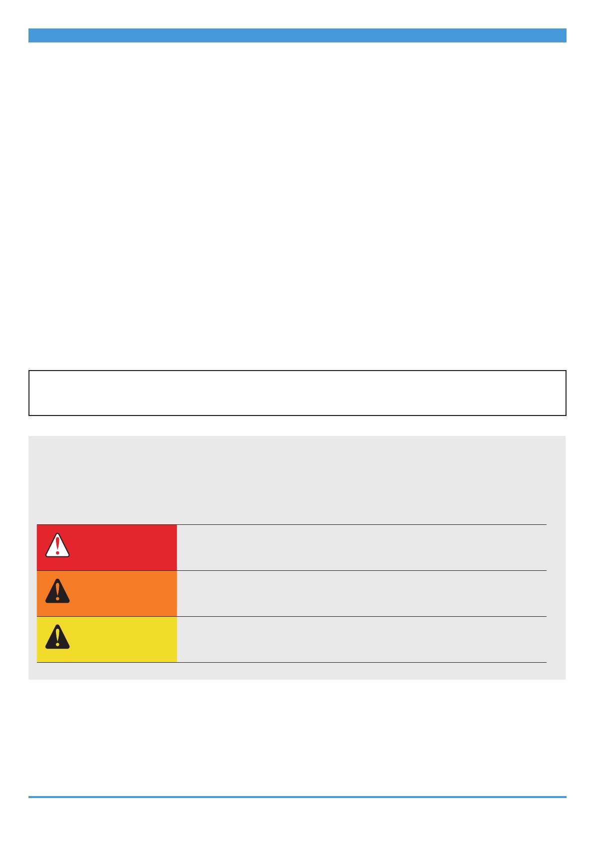
The instructions are classified according to the degree of danger or damage which may occur
if the product is used incorrectly.
DANGER
Failure to follow the instructions will result in death or serious
injury.
WARNING
Failure to follow the instructions could result in death or
serious injury.
CAUTION
Failure to follow the instructions could cause personal injury or
physical damage to equipment and surroundings.
4
TO ENSURE SAFETY
TO ENSURE SAFETY
WARNING
Be sure to follow the instructions provided in the manuals when installing the product.
Only use SHIMANO genuine parts. If a component or replacement part is incorrectly
assembled or adjusted, it can lead to component failure and cause the rider to lose
control and crash.
Install the sprockets with the wide protrusions and grooves aligned. If the lock ring is
tightened with the sprockets improperly positioned, the splines on the sprockets may be
damaged during tightening. That may cause a sudden release of resistance on the
wrench being used to tighten the lock ring, which in turn may cause injury. In addition, if
the bicycle is ridden with the sprockets improperly installed, damage or chain skip may
occur, which can cause the rider to fall over, resulting in serious injury.
Align the wide part
Second sprocket
Smallest sprocket
Wide part
Properly positioned state
Improperly positioned state
The protrusions on the smallest sprocket fit
into the indents in the second sprocket along
the entire circumference.
There are places where the protrusions on the
smallest sprocket overlap the indents in the
second sprocket.
Wear approved eye protection while performing maintenance tasks such as
replacing components.
5
TO ENSURE SAFETY
Be sure to also inform users of the following:
Clean the chain and QUICK-LINK with an appropriate chain cleaner regularly. Intervals
between maintenance depend on the use and riding circumstances. Never use alkali
based or acid based solvents, such as rust cleaners. If those solvents are used the chain or
QUICK-LINK might break and cause serious injury.
NOTICE
Be sure to also inform users of the following:
If the chain keeps skipping during use, consult the place of purchase.
Products are not guaranteed against natural wear and deterioration from normal use
and aging.
For maximum performance we highly recommend SHIMANO lubricants and maintenance
products.
For installation to the bicycle, and maintenance:
The gears should be periodically washed with a neutral detergent. In addition, cleaning
the chain with neutral detergent and lubricating it can be an effective way of extending
the life of the gears and the chain.
Always use the recommended combination of gears.
Always use CS-M9100/CS-M9101/CS-M8100/CS-M7100/CS-M6100 in combination with
CN-M9100/CN-M8100/CN-M7100/CN-M6100.
Other chains cannot be used because the dimensions do not match.
The actual product may differ from the illustration because this manual is
intended mainly to explain the procedures for using the product.
6
List of tools to be used
The following tools are needed for installation/removal, adjustment, and maintenance
purposes.
Tool
TL-LR10
TL-LR15
TL-SR24
Adjustable wrench
7
Installation/removal
Installing the cassette sprocket
Installation/removal
Installing the cassette sprocket
1. Place all of the sprockets other than the smallest sprocket on the
freewheel body.
For CS-M9100, place the low spacer first.
Then, place the sprockets in descending order from the largest sprocket.
Place the sprockets so that the wide convex section of the sprocket is aligned with the
wide groove in the freewheel body.
The marked side of the sprockets must be facing outward.
Wide part
Wide part
Low spacer (CS-M9100)
NOTICE
Do not stack more than 2 low spacers.
8
Installation/removal
Installing the cassette sprocket
2. Place the smallest sprocket.
Place the sprocket so that the wide part on the inner side of the smallest sprocket is
aligned with the wide part of the second sprocket.
Align the wide part
Second sprocket
Smallest sprocket
Wide part
TECH TIPS
There are sprocket alignment marks for 10T (smallest sprocket), 12T, and 14T.
Assemble it so that the marks of each sprocket are aligned.
Alignment mark
If the sprocket aligning marks are properly placed, it will be as shown in the
figure.
Alignment mark
9
Installation/removal
Removing the cassette sprocket
3. Place the lock ring into the freehub body and use a SHIMANO original
tool to tighten.
30 - 50 N·m
Lock ring
Removing the cassette sprocket
1. Remove the lock ring with a SHIMANO original tool.
Install TL-SR24 on the sprocket outward from the middle sprocket to secure the assembly.
If the TL-SR24 is set on a sprocket inward from the middle sprocket, it will not be stable.
Lock ring
2. Remove the cassette sprocket from the freehub body.
10
Installation/removal
Sprocket pattern
Sprocket pattern
CS-M9100
Sprocket spacer
Low spacer
Lock ring
Lock ring washer
10-51T 10-45T
Number of teeth Mark Number of teeth Mark
51,
45,
39,
33,
28,
24,
21,
18
51A,
45A,
39A,
33A,
28E,
24E,
21L,
18E
45,
40,
36,
32,
28,
24,
21,
18
45C,
40C,
36A,
32C,
28E,
24E,
21L,
18E
16 16C 16 16C
14 14C 14 14C
12 12C 12D 12 12C 12D
10 10A 10B 10 10A 10B
* 12C cannot be used with 10B, and 12D cannot be used with 10A.
11
Installation/removal
Sprocket pattern
CS-M9101
Sprocket spacer
Lock ring
Lock ring washer
10-51T 10-45T
Number of teeth Mark Number of teeth Mark
51,
45,
39,
33,
28,
24,
21,
18
51A,
45A,
39A,
33A,
28E,
24E,
21L,
18E
45,
40,
36,
32,
28,
24,
21,
18
45C,
40C,
36A,
32C,
28E,
24E,
21L,
18E
16 16C 16 16C
14 14C 14 14C
12 12C 12D 12 12C 12D
10 10A 10B 10 10A 10B
* 12C cannot be used with 10B, and 12D cannot be used with 10A.
12
Installation/removal
Sprocket pattern
CS-M8100
The thickness of the two sprocket spacers differs. Be careful when installing the sprocket
spacers.
Sprocket spacer (thick)
Sprocket spacer (thin)
Lock ring
Lock ring washer
10-51T 10-45T
Number of teeth Mark Number of teeth Mark
51,
45,
39,
33,
28,
24,
21
51B,
45D,
39B,
33B,
28F,
24F,
21M
45,
40,
36,
32,
28,
24,
21
45F,
40D,
36B,
32D,
28F,
24F,
21M
18 18F 18 18F
16 16C 16 16C
14 14C 14 14C
12 12D 12 12D
10 10B 10 10B
13
Installation/removal
Sprocket pattern
CS-M7100
The thickness of the two sprocket spacers differs. Be careful when installing the sprocket
spacers.
Sprocket spacer (thick)
Sprocket spacer (thin)
Lock ring
Lock ring washer
10-51T 10-45T
Number of teeth Mark Number of teeth Mark
51,
45,
39,
33,
28,
24,
21
51B,
45E,
39B,
33B,
28F,
24F,
21M
45,
40,
36,
32,
28,
24,
21
45F,
40E,
36B,
32D,
28F,
24F,
21M
18 18F 18 18F
16 16C 16 16C
14 14C 14 14C
12 12D 12 12D
10 10B 10 10B
14
Installation/removal
Sprocket pattern
CS-M6100
The thickness of the two sprocket spacers differs. Be careful when installing the sprocket
spacers.
Sprocket spacer (thick)
Sprocket spacer (thin)
Lock ring
Lock ring washer
10-51T
Number of teeth Mark
51,
45,
39,
33,
28,
24,
21
51C,
45E,
39C,
33B,
28F,
24F,
21M
18 18F
16 16C
14 14C
12 12D
10 10B
15
Maintenance
Replacing the adhesive ring
Maintenance
Replacing the adhesive ring
CS-M9101/CS-M8100/CS-M7100/CS-M6100
1. Remove the old adhesive ring.
2. Wipe clean any dirt, water, and oil on the surface where the adhesive
ring was affixed.
Affixing surface
NOTICE
The adhesive force weakens if there is any dirt, water, or oil on the surface where
the adhesive ring was affixed.
16
Maintenance
Replacing the adhesive ring
3. Affix a new adhesive ring.
Firmly press down on the adhesive ring so that it adheres firmly to the mating face of the
cassette.
Please note: specifications are subject to change for improvement without notice. (English)
© Nov. 2020 by SHIMANO INC. ITP
  • Page 1 1
  • Page 2 2
  • Page 3 3
  • Page 4 4
  • Page 5 5
  • Page 6 6
  • Page 7 7
  • Page 8 8
  • Page 9 9
  • Page 10 10
  • Page 11 11
  • Page 12 12
  • Page 13 13
  • Page 14 14
  • Page 15 15
  • Page 16 16
  • Page 17 17

Shimano CS-M9101 Dealer's Manual

Type
Dealer's Manual
This manual is also suitable for

Ask a question and I''ll find the answer in the document

Finding information in a document is now easier with AI