Page is loading ...

CEILING CASSETTE TYPE
AIR CONDITIONERS
OWNER'S MANUAL (UNIVERSAL SERIES)
Thank you for choosing our Air Conditioner. Please read this
OWNER'S MANUAL carefully prior to using and keep it for
further reference.
Safety Awareness
Name of Parts
Preparation Before Operation
Operation of Air Conditioner
Guide to Proper Usage
Service and Maintenance
3
5
6
13
Malfunction Codes
1
27
14
24K/36K/42K/48K
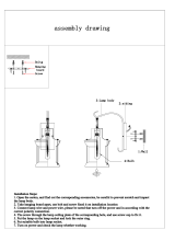
Installation Explanations
15
18K

1
Power resource must be supplied through one specific
circuit and ensure only one main power switch equipped.
Do not damage the power cord. Do not connect the wire
from the middle of the power cable or extend it. Piling up
heavy objects on the power cable, approaching high
temperature supply objects will cause electric shock and
fire.
The air conditioner must be earthed firmly.
Do not connect the earth wire to the gas pipeline, water
pipeline, lightning rod, or telephone earth wire.
Do not install the air conditioner near flammable
gas.
Ventilation at both air inlet and outlet must be allowed.
Blocking air flow may cause poor performance of unit
and also may cause irreparable damage.
Read and understand thoroughly this safety awareness before use.
The items indicated here are very important safety precautions, which must be followed.
SAFETY AWARENESS
An earth leakage breaker with rated capacity and fuse
must be installed to avoid possible electric shocks and fire.
Do not install the air conditioner at acidic, smoggy
environment or where steam occurs. Otherwise, it will
greatly degrade the machine performance and thus
cause irreparable damage.
Do not apply the cool air to humans, animals, plants,
etc. (Especially there are babies, aged persons and
patients in the room)
Ensure that the drainage is correct. Dripping water
may cause damage to furniture, due to poor drainage.
Breaker
Power switch
Earth wire
This product must not be disposed
together with the domestic waste.
This product has to be disposed at an
authorized place for recycling of
electrical and electronic appliances.

2
Warning:
Do not insert a finger, a rod or any other objects into the
air outlet/inlet grille. As the fan is running at a high speed,
it will cause injury.
Do not eject any insecticide or flammable spray towards
the surface of the air conditioner. Otherwise, it may cause
fire.
Before cleaning, be sure to stop the operation and shut
off the power supply!
For cleaning, do not use water, inflammable things or any
other material, which will damage the
surface of the unit and lead to
electric shock or fire.
Periodically open the door and window for a moment to get
some fresh air from outside since the room air may turn
turbid after the air conditioner has been running for a
long time.
The air conditioner will not auto restart after a power
failure. When the power resumes, please restart the air
conditioner with the operation of the remote controller.
If you find anything abnormal occurs(such as burning
smell during operation),please immediately stop the
operation , turn off the air conditioner and contact your
local authorised service centre to check the air conditioner.
If you find one of the following symptoms, please turn the
breaker off quickly and call our authorised service centre
for help.
The creepage switch always jumps to turn off.
The display panel fails to display normally.
Something abnormal compared with the usual operation.
Some switch or button often fails to work normally.
Do not attempt to install, service or move the Air Conditioner by yourself.
Incorrect may cause fire, electric shock and the unit falling may
result in injury or water leakage. Contact our designated air conditioner
service centre and specialists. The manufacturer shall not assume
responsibility for accidents or injury caused by incorrect
connection
connection.
Read and understand thoroughly this safety awareness before use.
The items indicated here are very important safety precautions, which must be followed.
SAFETY AWARENESS
Off
This appliance is not intended for use by persons (including children) with
reduced physical,
sensory or mental capabilities, or lack of experience and knowledge, unless they have been
given supervision or instruction concerning
use of the appliance by a person responsible for
their safefty.
Children should be supervised to ensure that they do not play with the appliance.

NAME OF PARTS
THE INDOOR UNIT
A
D
E
C
F
B
The indoor display panel
A. Air inlet: takes in the room air
B. Air outlet
C. Deflector: adjust the outlet air direction
D. Filter
E. Panel
F. Remote controller
3
SWINGSWING
OPERATIONOPERATION
MODEMODE
SLEEPSLEEP
FAN SPEEDFAN SPEED
I/OI/O
TIMETIME AUX-HEATAUX-HEAT
A
D
E
C
F
B
The indoor display panel
Emergency switch
A. Air inlet: takes in the room air
B. Air outlet
C. Deflector: adjust the outlet air direction
D. Filter
E. Panel
F. Remote controller
SWINGSWING
OPERATIONOPERATION
MODEMODE
SLEEPSLEEP
FAN SPEEDFAN SPEED
I/OI/O
TIMETIME AUX-HEATAUX-HEAT
For models of 24K, 36K, 42K, 48K
For model of 18K
Emergency switch
TIMER lamp
ALARM lamp
DEFROSTING / PREHEATING lamp
Remote Signal Receiver
RUN lamp
TIMER lamp
ALARM lamp
DEFROSTING / PREHEATING lamp
RUN lamp

NAME OF PARTS
4
REMOTE CONTROLLER
Cool only type has no HEAT mode.
SWING
MANUAL
OFF
ON
CANCEL
SET
SLEEP
FAN SPEED
OPERATION
MODE
I/O
TIME
MANUAL
SWING button
SWING button
TIMER ON button
TIMER OFF button
TIMER SET button
TIMER
CANCEL button
RESET pieces
Remove the batteries if the remote controller is not to be used for long periods of time.
In this illustration, all displays are ON for the purpose of explanation. Some models
may not show all these indications.
NOTICE:
Press it to change up/down air
flow direction and the deflector
automatically swings up and
down.
Please see“AUTO-ON/OFF
timer operation”.
Press it to fix the timer setting.
Press it to cancel the timer
setting.
If the remote controller can't
work normally, short the two
RESET pieces, it will be OK.
It sends signals to the indoor unit.
(1) (2) (3) (4)
(5)
Press it to change up/down air
flow direction and the deflector
moves at a certain angle. You
can change the moving angle
in the order of:
Signal ejecting window
TEMPERATURE
ADJUSTMENT buttons
RUN/STOP button
OPERATION DISPLAY
FAN SPEED button
OPERATION
MODE button
SLEEP button
COOL
HEAT FAN DRY
AUTO
Press once, the setting
temperature increases by 1.
Press once, the setting
temperature decreases by 1.
The range of setting
temperature is 16-31 .
It displays the current
settings.
Press it to select operation
mode:
Turns unit ON/OFF.
Press it to change the fan speed
in the order of low-medium-high
-auto ( ).
Don't tear the batteries apart or throw them into fire, which will lead to irreparable damage.
Press it to start sleep function
and press again to stop it.
Please see“AUTO-ON/OFF
timer operation”.
To operate, the distance should be within 6 meters from the indoor unit with a clear
line of sight.

1
1 2
PREPARATION BEFORE OPERATION
Open the back cover, put in
batteries and reset the back cover
as before.
Short RESET pieces with
appropriate metal object.
The signal can be reached within six metres directly in front of
indoor unit.
If the remote controller does not work, short the RESET pieces
Handle remote controller carefully. Do not drop, throw and get
it wet.
When the button is pressed, indoor unit will beep once or twice,
indicating the receiving of the signal. If no beep is heard, press
again.
Remove batteries if the remote controller
is not being used for a period of time.
NOTICE
5

OPERATION WITH REMOTE CONTROLLER
Run/Stop
Press I/O button once to start operation and press it again to stop operation.
Temperature Adjustment
Sleep Selection
Press sleep button once to start sleep function and press it again to stop sleep
function.
Once activating sleep function, the sleep indicator lamp will illuminate on the
operation panel of the indoor unit.
Fan Speed Adjustment
Press FAN SPEED button to change the fan speed of indoor unit in the order
of: low medium high auto ( )
11
1
2
2
3
3
14
4
Every press of button increases the setting temperature by 1 , every
press of button decreases the setting temperature by 1 .
¡° ¡±
The set temperature will be shown on display panel of the remote controller.
¡°
The range of setting temperature is 16-31 .
Once the air conditioner starts operation, it will sound beep once and the
run indicator lamp is illuminated.
Air flow direction adjustment
Air flow by swinging
Press swing button on the remote controller, the deflector will swing up and down.
115
5
Directional air flow
When the deflector moves at your desired angle, press swing button on the
remote controller, the deflector stops to blow directional air flow.
OPERATION OF AIR CONDITIONER
6
Operation mode selection
Press mode selection button on the remote controller to choose the following mode:
116
6
AUTO mode
In this mode, the air conditioner can automatically adjust the room temperature to
decide the most suitable temperature. At the start of operation, the air conditioner
will automatically select the operation mode depending on room temperature.
Please refer to the following:

COOL mode
DRY mode
FAN mode
HEAT mode (only applied to heat pump type)
In this mode, press temperature adjustment button to set temperature; press fan
speed button to change airflow speed of the indoor unit.
Press SWING button to set the airflow angle or adjust the vane swinging up and
down.
In this mode, only the indoor unit runs like the fan. Press fan speed button to
change the airflow speed and press swing button to set the airflow angle.
COOL DRY FAN
COOL DRY FAN HEAT
COOL ONLY TYPE:
HEAT PUMP TYPE:
In this mode, the air conditioner automatically decides the setting temperature
and this setting temperature will not appear on display. Neither the setting
temperature nor the fan speed could be adjustable. You can press SWING button
to set the airflow angle.
Press mode selection button on the remote controller to cycle the mode in the
following order:
In this mode, press temperature adjustment button to set temperature; press fan
speed button to change the airflow speed of the indoor unit.
Press swing button to set the airflow angle or adjust the vane swinging up and down.
¡±
Selected mode
Heating (For cooling only type, dehumidifying mode is selected)
Fan
Cooling
Room
Temperature (RT)
RT 20
RT 24
20 RT 24
OPERATION OF AIR CONDITIONER
7
B. After one hour of operation the set temperature will decrease by 2 . One hour later,
the set temperature will decrease by 2 once more. The unit will then continue
operating at 4 below the set temperature.
B. After one hour of operation the set temperature will increase by 1 . One hour later,
the set temperature will increase by 1 once more. The unit will then continue
operating at 2 above the set temperature.
A. The indoor fan runs at low speed.
Sleep mode in heating running.
SLEEP mode
A. The indoor fan runs at low speed.
Sleep mode in cooling and drying running.

Timer operation
11
7
7
OPERATION OF AIR CONDITIONER
8
NOTICE:
2).Once the AUTO-ON/OFF time is fixed, if you want to change it, you should cancel
the previous AUTO-ON/OFF timer operation.
3).If you press the button once incautiously after the AUTO-ON/OFF time is fixed,
the system will count time anew based on the current display time.
SET
1).TIMER ON/OFF operation must be set again after a power failure.
1. when the air conditioner is on to initiate the AUTO-OFF TIMER
function. Meanwhile, of starts to flash on the display.
Press button
3.Press button to set the AUTO-ON/OFF time. The or will stop flashing
on the remote controller display.
AUTO-ON/OFF timer operation cancellation
If you want timer operation cancelled, press button until the digits of
AUTO-ON/OFF time and or disappear on the remote controller display.
CANCEL
AUTO-ON/OFF timer operation set
OFF
ON
OFF
ON
¡±
SET
¡±
Press button when the air conditioner is off to initiate the AUTO-ON TIMER
function. Meanwhile, of starts to flash on the display.
2.Every press of button or increases the AUTO-ON/OFF time by one hour
(12 hours at most) and the digits of AUTO-ON/OFF time will appear on the display.

INDICATION LAMP
ON/OFF
UP
DOWN
TIME
TIME
RESET TIME
MODE
SET
INQUIRY
LIGHT
WAVE
SWING
SLEEP
FAN
SPEED
OPERATION OF AIR CONDITIONER
WIRE CONTROLLER (OPTIONAL)
LCD screen
Remote signal receiving spot
AUTO
COOLING
DEHUMIDIFYING
FAN
HEATING
AUTO-ON
AUTO-OFF
MONTH DATE MINUTEHOUR
LIGHT WAVE
STERILIZATION
ELECTRIC HEATER
FAN
SPEED
SLEEP
DEFROSTING
ANTI-FREEZING
COOLING
PUMP
PIN LOCK
Instruction of symbols on LCD screen
(some symbols may be displayed in practice)not
COMPRESSOR
9

When installing back cover of wire controller, fit the lower back cover into the
body, hold on and click the upper part into the body, then push them together.
When dismantling the back cover, follow the steps below:
Installation of Wire Controller
slot (rectangular shape,
sleeping between back
cover and body, turn
wire controller into a certain
angle then you can see it)
slot
top
click click
LCD Screen
Front Panel
Put a flat screw driver into a slot,
unclench one side of the cover,
then another slot, and unclench
another side of the cover, then you
can open the cover.
Note: Do not push the front panel of wire controller with force to avoid crushing
the LCD screen or internal PCB board.
OPERATION OF AIR CONDITIONER
10

OPERATION OF AIR CONDITIONER
11
OPERATION WITH WIRE CONTROLLER
Run/Stop
When ON/OFF button is pressed once, the unit starts and the green lamp illuminates.
Temperature Adjustment
Sleep Selection
Press SLEEP button once to start sleep function and press it again to stop sleep
function.
Once activating sleep function, the sleep indicator lamp will illuminate on the
LCD screen of the wire control, and the fan will run at low speed.
Fan Speed Adjustment
Press FAN SPEED button to change the fan speed of indoor unit in the order
of (the grey part is flashing):
11
1
2
2
3
3
14
4
Every press of UP button increases the setting temperature by 1 , every
press of DOWN button decreases the setting temperature by 1 .
¡° ¡±
¡°
The range of setting temperature is 18-31 .
When ON/OFF button is pressed again, the unit stops and the red lamp illuminates.
Low Medium High Auto
Air flow direction adjustment
115
5
Press SWING button to change the air flow directions of indoor unit in the order
of (the grey part is flashing):
Auto
Swing
Manual
Position 1
Manual
Position 2
Manual
Position 3
Manual
Position 4
Manual
Position 5

OPERATION OF AIR CONDITIONER
12
Operation mode selection
116
6
When the unit is at standby state, press MODE button to change its operation modes
in the order of:
Cooling Dehumidifying Fan Heating Auto
Date/Time Setting
11
7
7
Timer Operation
11
8
8
At normal display page, press TIME button to set the AUTO-ON timer and
meanwhile the lamp illuminates, while press TIME button to set the
AUTO-OFF timer and meanwhile the lamp illuminates
At normal display page, press TIME button once to set the Date/Time and
meanwhile the beeper raises Bi sound once; press the TIME button again to
finish the setting and meanwhile the beeper raises Bi sound twice.
When setting the timers, press TIME or TIME to shift the setting items
between timer parameter and timer date/time.
When setting the timers, press UP or DOWN to change the values of
timer parameter and timer date/time.
Timer parameters:
00: Invalid timer setting; 01: Valid single-timer; 02: Valid circulated timer.
When setting the timers, press TIME button once to finish the timer setting, and
meanwhile the beeper raises Bi sound twice.
Light Wave function selection
119
9

OPERATION OF AIR CONDITIONER
Press LIGHT WAVE button once to start light wave function and press it again to
stop the function.
Once activating light wave function, the lamp will illuminate on the LCD
screen of the wire control.
Fault and temperature inquiry
1110
10
At sensor temperature inquiry page, press UP or DOWN button to
inquiry the temperatures:
A0: Room temp.; A1: Indoor coil temp.; A2: Outdoor ambient temp.; A3: Outdoor
coil temp.;
Every press of ENQUIRY button changes the display pages between normal display
page , sensor temperature inquiry page , current fault inquiry page (if the unit
is at fault) and history fault inquiry page (if there are faults recorded).
At current fault inquiry page, the lamp is flashing, and the fault code is shown
on the wire control.
At history fault inquiry page, the lamp is on, and the fault time, fault code and
fault No. are displayed on the wire control.
Reset Function
1111
11
When the unit is at fault and the lamp is on, press RESET button to unlock
the fault lock with a Bi sound indication.
At history fault inquiry page, press RESET button for 10 seconds to remove the
fault record with a Bi sound indication.
Unit Parameter Inquiry
1112
12
When the unit is off, press SET button for 5 seconds until the beeper raises a Bi
sound, and then press SET button again to move into unit parameter inquiry
mode (ignore keying in the password).
At unit parameter inquiry mode, press TIME and TIME to change the
parameters to be checked.
13

OPERATION OF AIR CONDITIONER
Unit Parameter modification
1113
13
When the unit is off, press SET button for 5 seconds until the beeper raises a Bi
sound, and then enter the right password and press SET button again to move
into unit parameter modify mode (The word PASS will show up).
Note: Contact the local dealer for the password.
At unit parameter modification mode, press TIME and TIME to select
the parameters to be changed; press UP and DOWN to change the
parameters; Press RESET button to restore all the parameters to factory setting.
04
05
06
07
Parameters
03
08
Normal range
Default value
Instructions
NOTICE
The parameter modification must be permitted by the manufacturer, otherwise the
manufacturer will not be responsible for any problems caused by the modification.
NO.
10
11
12
13
09
14
02
01
15
Coil over-heating protection in heating
Compressor minimum standby time
Compressor minimum running time
Defrosting time
Coil anti-freezing protection in cooling
Outdoor coil temp. to end defrosting
Fahrenheit or Celsius temperature
12 hours or 24 hours mode
Mode changing setting
Automatic restarting
Fan high speed shielding setting
Outdoor coil temp. compensation
Room temp. compensation
Light wave generator/Crankcase heater
Shielding time of low pressure protection
50 ~80
0~10 mins
0~10 mins
-5 ~15
0~10 mins
8~20 mins
0/1
0/1
0/1
8~20
0/1
0/1
0/1
-5 ~5
-5 ~5
65
3mins
3mins
-2
3mins
8mins
0
0
0
12
0
0
0
0
0
0: enable; 1: disable
0:Celsius; 1:Fahrenheit
0:24 hours; 1:12 hours
0:On standby or running state,
mode changing is available;
0:Three fan speeds ;
1: Shielded high speed
0:Light wave generator;
1:Crankcase heater
“--” means outdoor coil sensor
detection is shielded.
1:On running state, mode changing
is unavailable;
14

15
When cooling, keep away from
heat supply objects
off
Taking care of your unit will allow you to enjoy a more comfortable
cooling&heating effect and save more energy.
Clean the air purifying filter
periodically
If the air purifying filter becomes clogged
with dust/dirt, air flow is restricted and
thus reduces cooling&heating efficiency.
Please clean the air purifying filter at
least once every two weeks.
During cooling, draw the curtains
especially for the windows facing the sun
to reduce the incoming heat ; Besides,
reduce the frequency of door opening as
much as possible.
Switch off the power supply and
remove batteries from your remote
control, if the air conditioned is
not being used for a period of time.
Once the power supply is switched on,
the air conditioner will consume electric
power even if it does not run. So
switching off the power supply can save
energy. If the air conditioner is not being
used for a period of time, remove
batteries from the remote controller as
these may leak, causing damage.
Set the room temperature to your
suitable point
During cooling, increase of 1 will save
energy by 10%.
Too low room temperature will do harm
to your health and also wastes energy.
GUIDE TO PROPER USAGE
During cooling, a difference of 5
between the indoor and outdoor
temperature will suit you better.
a difference of 5
between the indoor
and outdoor
temperature
C

OFF
If you are not using the air conditioner for a long period of time.
Set the fan of the indoor unit going for 3 to 4 hours to dry out the inside
thoroughly.
Switch off the air conditioner and unplug it from the wall socket.
Clean the air filters and the indoor unit thoroughly.
Remove the batteries out of the remote controller and put away the remote
controller.
Cover the indoor and outdoor unit with shield to keep off the dust.
If you have not used the air conditioner for a long period
Check whether both the air inlet and outlet are blocked.
Check whether the drain pipe is blocked, or if there is twist or terminal lift-up.
Check whether the air filters are appropriately mounted.
SERVICE AND MAINTENANCE
16
Cleaning of the indoor unit
Wipe the indoor unit with a piece of dry , clean cloth.
All the cleaning and maintenance work shall be done by qualified person.
Before cleaning or servicing, be sure to stop the operation and turn off
the power supply.
Cleaning of the air filter and the indoor unit
1.Remove the air inlet grille and air filter.
2.
3.Dry the air filter in the shade, do not parch!
4.Place the air inlet grille and air filter as they were.
Remove all dust on the front grille and air filters with a vacuum cleaner or brush.
( If the dust does not come off easily, wash them with neutral detergent dissolved
in warm water below 45 .)
Cleaning of the air filter
Air filter
Air inlet grille

Location of the indoor unit
INSTALL LOCATION INSTRUCTION
Mount on the roof or truss solid enough to bear the weight of the indoor unit.
A place easy for air circulation around all corners.
Keep the air inlet and outlet at a far distance from the blockage.
Avoid places where there are steam, lampblack and inflammable gas.
Keep away from some equipment of high frequency. (Such as soldering machine)
Avoid places near the fire alarm, for hot air may trigger the fire alarm during heating.
Avoid places where there are spraying acidity liquor or sulphur.
Certain maintenance space must be left, please see the following requirement:
1. Ceiling
2. Ceiling inlaid board.
4. Maintenance space of 1m above.
5. Maintenance space of 50cm above.
3. Obstacle.
6. Panel
Location of the outdoor unit
Avoid direct sunshine.
Avoid strong wind.
Avoid places close to inflammable gas.
A place easy for conjunction with the power supply as well as with the indoor pipe.
A place where the operation noise will not annoy your neighbours.
Avoid installing on the shelf which may strengthen the noise and shake.
Watch for the condensation water discharging out of the chassis.
Arrange the height difference of both indoor and outdoor units, the length of
refrigerant pipe, number of bent position of pipe as the following requirement:
The indoor unit
A
B
C
30m
Lower than
15m
Less than
15
The outdoor
unit
Length of Pipe A (one way)
B:Height
difference
C: The number of
bent position of pipe
CHOICE OF INSTALL LOCATION
11
55
44
33
66
22
17
The appliance must not be installed in the laundry.
The appliance must be installed 2.3m above floor.

A. Distance of eyebolt
B. Size of outer edge of the unit
C. Ceiling opening size
D. Size of outer edge of the panel
E. For 24K:230mm
For 36K, 48K:300mm
THE SIZE OF CEILING OPENING AND HANGING RING
Please notice the following size of ceiling opening, and its value may vary as the
practical installation.
INSTALLATION OF THE INDOOR UNIT
18
Installing hanging hook
780 A
840 B
880 C
950 D
680 A
840 B
880 C
950 D
880
Ceiling
Panel
E
580 A
610 B
630 C
650 D
410 B
580 A
630 C
650 D
A. Size of outer edge of the unit
B. Distance of eyebolt
C. Ceiling opening size
D. Size of outer edge of the panel
E. For 18K:255mm
For model of 18K:
For models of 24K, 36K, 42K, 48K:
Installing hanging hook
Ceiling
Panel
E

DESIGN OF STRUCTURE FOR HANGING
A. Indoor unit
B. Panel
C. Gasket
Please fix the inflate bolt F on the mounting plate as the picture1 shown
Attention: check the inflate bolt to ensure that it is not loose.
Fix the mounting bracket onto the inflate bolt F and then the eyebolt shall be
fit as picture 2 shown.
A. Eyebolt
B. Nut
C. Spring washer
D. Flat washer
E. Mounting bracket
F. Inflate bolt
Notice:
For the sake of safety assurance, the place for hanging must bear enough
strength and pressure.
The ceiling should keep horizontal. If installed on the declining ceiling,
gasket must be inserted between the ceiling and panel.
C
B
A
120mm120mm
FF
EE
D D
CC
BB
AA
Picture 1-a (bottom view)
(For 18 K)
Install on the roof of reinforced concrete structure.
Picture 2
INSTALLATION OF THE INDOOR UNIT
19
Picture 1-a (bottom view)
(For 24K, 36K, 42k, 48K)
/