Page is loading ...

The Worlds Leading Cellular
Telephone Manufacturer
Service Manual
DCS StarTac
Cellular Subsciber Group
68P09304A85

DCS1800 StarTAC PERSONAL
CELLULAR TELEPHONE
Module Level
Repair Manual
68P09304A85-O

DCS 1800 StarTAC CELLULAR TELEPHONE
68P09304A85-0 AGen1
19/07/97
PERFORMANCE SPECIFICATIONS -DCS 1800 StarTAC
GENERAL
TRANSMITTER
RECEIVER
SPEECH CODING
Specifications are subject to change without notice
CAUTION
Do not jump start vehicle or use an automotive battery charger while the vehicle adapter
option and the portable radiotelephone are connected to the vehicle electrical system as this
may cause serious damage to the radio. Disconnect the radio by removing the cable kit fuses.
Frequency Range 1710-1785 MHz Tx
1805-1880MHz Rx
Channel Spacing 200 kHz
Number of Channels 375 carriers with 8 channels per carrier
Modulation GMSK at BT = 0.3
Transmitter Phase Accuracy 5 Degrees RMS, 20 Degrees peak
Duplex Spacing 95MHz
Frequency Stability +/- 0.1 ppm of the downlink frequency (Rx)
Voltage Operation +3V to +5.1V dc (Battery) and +4.4V to +6.5V (External connector
Transmit Current <260 mA at 1 Watt
Stand-by Current 15mA nominal
Dimensions 98.3 mm (L) x 57.3 mm(W) x 23 mm(D)
Size (Volume) 100 cubic cm
Weight Approximately 98.5g; with Light Lithium Ion 350mAh battery and antenna
Temperature Range -20°C to +55°×C
RF Power Output 30 dBm nominal
Output Impedance 50 ohms (nominal)
Spurious Emissions -36 dBm up to 1 GHz, (<-30 dBm > 1 GHz)
Rx Bit Error Rate (100kbits) <2% @ -100 dBm
Channel Hop Time 500 microseconds
Time to Camp Approximately 10 seconds
Speech Coding Type Regular Pulse Excitation / Linear Predictive Coding with Long Term Prediction. (RPE
LPC with LTP.
Bit Rate 13.0 kbps
Frame Duration 20 ms
Block Length 260 bits
Classes Class 1 bits = 182 bits. Class 2 bits = 78 bits
Bit Rate with FEC Encoding
22.8 kbps
COMPUTER SOFTWARE COPYRIGHTS
The Motorola products described in this instruction manual may include copyrighted Motorola computer programs stored in semiconductor memories
or other media. Laws in the United States and other countries preserve for Motorola certain exclusive rights for copyrighted computer programs,
including the exclusive right to copy or reproduce in any form the copyrighted computer program. Accordingly, any copyrighted Motorola computer
programs contained in the Motorola products described in this instruction manual may not be copied or reproduced in any manner without the express
written permission of Motorola. Furthermore, the purchase of Motorola products shall not be deemed to grant either directly or by implication, estoppel,
or otherwise, any license under the copyrights, patents or patent applications of Motorola, except for the normal non-exclusive, royalty free license to
use that arises by operation of law in the sale of a product.
© Motorola Ltd. 1997
All Rights Reserved
Printed in U.K.

Customer Services Publishing
Easter Inch, Bathgate, West Lothian,
EH48 2EH, United Kingdom
AGen1
© Motorola Ltd. 1997
All Rights Reserved
Printed in U.K.
DCS 1800 StarTAC PERSONAL
CELLULAR TELEPHONE
CONTENTS LIST
19/07/97
Cellular Subscriber Group
SECTION 1 - GENERAL PAGE NUMBER
FOREWORD ix
MOTOROLA SERVICE POLICY ix
GENERAL SAFETY INFORMATION x
SECTION 2 - DESCRIPTION
SYSTEM DESCRIPTION 1
DCS SYSTEM OVERVIEW 1
TELEPHONE DESCRIPTION 5
FEATURE LIST 7
SECTION 3 - LABELLING & SIM CARDS
TRANSCEIVER LABELLING 9
INTRODUCTION 9
TITLE EXPLANATIONS 9
SIM CARDS 11
INTRODUCTION 11
SIM CARD INSERTION/REMOVAL 11
SECURITY INFORMATION 11
SECTION 4 - MANUAL - TEST MODE & VERIFICATION
MANUAL-TEST MODE 13
INTRODUCTION 13
TEST SIM INSERTION/REMOVAL 13
ACCESSING THE MANUAL-TEST MODE 13
VERIFICATION 15
INTRODUCTION 15
EQUIPMENT CONFIGURATION 15
TESTING PROCEDURE 16
iii

DCS 1800 StarTAC CELLULAR TELEPHONE
68P09304A85-0 AGen1
19/07/97
SECTION 5 - TROUBLESHOOTING
TROUBLESHOOTING 17
INTRODUCTION 17
TROUBLESHOOTING AND REPAIR 17
TESTING AFTER REPAIR 17
PIN OUT CONNECTIONS 18
TROUBLESHOOTING AND REPAIR CHART 19/21
SECTION 6 - PERSONALITY TRANSFER
PERSONALITY TRANSFER 23
INTRODUCTION 23
NORMAL TRANSFER 23
MASTER TRANSFER 24
MASTER SIM CARD CREATION 24
SECTION 7 - DISASSEMBLY
DISASSEMBLY INSTRUCTIONS 25
INTRODUCTION 25
RECOMMENDED TOOLS 25
DISASSEMBLY PROCEDURE 25
ASSEMBLY PROCEDURE 25
STEP BY STEP DISASSEMBLY 26/35
EXPLODED DIAGRAM AND PART NUMBERS 36/37
SECTION 8 - ACCESSORIES
RECHARGEABLE BATTERY PACKS 39
INTRODUCTION 39
RECHARGING 40
EXPERT PERFORMANCE BATTERIES AND CHARGERS 40
BUILT IN E.P BATTERY FAST CHARGER 40
iv

CONTENTS
AGen1 68P09304A85-O
19/07/97
SECTION 8 - ACCESSORIES (cont) PAGE NUMBER
NI-MH BATTERY PACKS 41
LITHIUM ION BATTERY PACKS 43
AUXILIARY BATTERY PACK 45
RAPID E.P BATTERY CHARGER 47
RAPID BATTERY CHARGER TRANSFORMER 49
CIGARETTE LIGHTER ADAPTOR/CHARGER 51
CAR KITS 53
INTRODUCTION 53
INSTALLATION INTRODUCTION 54
CAR KIT CONNECTION DIAGRAM 55
INSTALLATION PLANNING 56
COMPONENT LOCATION 56
ELECTRICAL SYSTEM POLARITY 56
USING FUSE LOOPS 56
MINIMIZING ELECTRICAL NOISE 56
CONVENIENCE ON/OFF FEATURE 56
CABLE ROUTING 57
POSSIBLE INTERFERENCE WITH ABS SYSTEMS 57
INSTALLATION 57
MOUNTING THE SMART HANDSET CRADLE 57
DHFA (ADAPTER BOX) 57
StarTAC CRADLE 58
ELECTRICAL CONNECTIONS 58
ENTERTAINMENT MUTE/AUX ALERT 59
MICROPHONE INSTALLATION 59
EXTERNAL SPEAKER INSTALLATION 59
EXTERNAL ANTENNA INSTALLATION 59
PERFORMANCE CHECKS 60
CHECKING ANTENNA PERFORMANCE 60
CHECKING ANTI SKID BRAKING SYSTEMS 61
SECTION 9 - FEED BACK FORM
FEED BACK FORM
v

DCS 1800 StarTAC CELLULAR TELEPHONE
68P09304A85-0 AGen1
19/07/97
TYPICAL MODEL COMPLEMENT FOR DCS 1800 StarTAC
Motorola DCS StarTAC S5993ABB
Motorola/One2One DCS StarTAC S5990ABB
Motorola/E-Plus DCS StarTAC S6220ABF
Motorola/Orange DCS StarTAC S5991ABB
Motorola/Bougues DCS StarTAC S5992ABE
Note: In addition to the above, VIP versions are available for the Motorola/E-Plus and the Motorola kits. Both feature the
addition of a Desktop Charger (SPN4325) and an auxiliary Battery (SNN4598).
Model Description
Quantity
Supplied
SUG1120A
SUG1120A
Transceiver
One2One Transceiver
1
1
SNN4667 Standard Battery
1
SPN4278+SYN4656 Travel Charger + UK plug
1
SYN5378 Belt holster
User manual in local language
1
1
Model Description
Quantity
Supplied
SUG1043A Transceiver
1
SNN4667 Standard Battery
1
SPN4278+SYN4655 Travel Charger + Euro plug
1
SYN5378 Belt holster
User manual in local language
1
1
Model Description
Quantity
Supplied
SUG1043A Orange Transceiver
1
SNN4667 Standard Battery
1
SPN4278+SYN4656 Travel Charger + UK plug
1
SYN5378 Belt holster
User manual in local language
1
1
Model Description
Quantity
Supplied
SWF2210A Transceiver
1
SNN4667
SNN4598
Standard Battery
Auxiliary Battery
1
1
SPN4278+SYN4656 Travel Charger + UK plug
1
SYN5378 Belt holster
User manual in local language
1
1
viii

DCS 1800 StarTAC CELLULAR TELEPHONE
68P09304A85-0 AGen1
19/07/97
1. SCOPE OF MANUAL
This manual is intended for use by experienced technicians familiar with similar types of equipment. It contains all service information
required for the equipment described and is current as of the printing date. Major changes which occur after the printing date are
incorporated by Cellular Manual Revisions (CMR). These CMR’s are added to the manuals as the engineering change is incorporated
into the equipment.
2. MODEL AND KIT IDENTIFICATION
Motorola equipments are specifically identified by an overall model number on the nameplate. In most cases, assemblies and kits
which make up the equipment also have kit model numbers stamped on them. When a production or engineering change is incorporated,
the applicable schematic diagrams are updated.
MOTOROLA SERVICE POLICY (DCS 1800) StarTAC
Warranty:
Product will be sold with the standard 12 months warranty terms and conditions.
Accidental damage, misuse, and retailers extended warranties will not be supported under warranty. Non warranty repairs
will be available at agreed fixed repair prices. Proof of purchase will be required to validate warranty claims.
Core Product
:
Motorola only branded product will be supported under a Low tier DCS Loaner program or alternative low cost service
strategy (To be agreed with the European Customer Service Managers). The customers original telephone will be repaired
but not refurbished as standard.
Appointed Motorola Service hubs may perform both Warranty and Non Warranty field service for Level 2 (module repair)
and 3 (Limited component). The Motorola HTC’s will perform full Level 4 (full pcb component level) repairs.
Customer support (End User)
:
This will be available through the operator own dedicated Call Centres and In Country Help Desks. Operators will be
supported as required by the local Motorola Country Service Manager.
Product Service training should be arranged through the local Motorola National Support Centre.
REPLACEMENT PARTS ORDERING
Only centres authorized by Motorola to carry out repairs will be able to purchase spare parts. Orders for spare parts from
HUB’s, Motorola National Support Centres and Hi-Tech Centres, should be placed with the appropriate Motorola Parts
Distribution Centre.
BOARD REPAIRS
All centres authorized to carry out module level repairs, must return faulty boards to the appropriate HUB or Motorola Hi-
Tech Centre for repair to component level.
FOREWORD
ORDERING INFORMATION
ix

CONTENTS
AGen1 68P09304A85-O
19/07/97
GENERAL SAFETY INFORMATION
PORTABLE OPERATION:
DO NOT hold the radio so that the aerial is very close to, or touching, exposed parts of the body, especially the
face or eyes whilst transmitting. The radio will perform best if it is held in the same manner as you would hold
a ‘land’ telephone handset, with the aerial angled up and over your shoulder.
DO NOT operate the portable phone in an aircraft. Switch off your telephone. The use of a cellular telephone
in an aircraft may be dangerous to the operation of the aircraft, disrupt the Cellular Network, and is illegal.
Failure to observe this instruction may lead to a suspension or denial of Cellular Telephone Service to the
offender, or legal action, or both.
MOBILE/PORTABLE OPERATION - Telephone use in Vehicles
:
All equipment must be properly grounded according to installation instructions for safe operation.
Users are advised to turn off their equipment when at a refuelling point.
Safety is every drivers business. Cellular telephones should only be used in situations in which the driver
considers it safe to do so.
GENERAL
:
DO NOT allow children to play with any radio equipment containing a transmitter.
DO NOT operate this equipment near electrical blasting caps or in an explosive atmosphere. Mobile telephones
are, under certain conditions, capable of interfering with blasting operations. When you are in the vicinity of such
work, look out for and observe signs cautioning against mobile radio transmission. If transmission is prohibited,
you must turn off your mobile telephone to prevent any transmission.
In standby mode the mobile telephone will automatically transmit to acknowledge a call if it is not turned off
.
Refer to the appropriate section of the product user manual for additional pertinent safety information
All equipment should be serviced only by a qualified technician.
x

Customer Services Publishing
Easter Inch, Bathgate, West Lothian
EH48 2EH, United Kingdom
BDesc2
© Motorola Ltd. 1997
All Rights Reserved
Printed in U.K.
DCS 1800 StarTAC PERSONAL
CELLULAR TELEPHONE
DESCRIPTION
GENERAL
68P09304A85
19/07/97
1
Cellular Subscriber Group
SYSTEM DESCRIPTION
1. D.C.S. SYSTEM OVERVIEW
1.1 GENERAL CELLULAR CONCEPT
The cellular systems are used to provide radiotelephone
service in the frequency range 1710-1880MHz. A cellular
system provides higher call handling capacity and system
availability than would be possible with conventional
radiotelephone systems (those which require total system
area coverage on every operating channel) by dividing the
system coverage area into several adjoining sub-areas or
cells.
Each cell contains a base station (cell site) which provides
transmitting and receiving facilities, for an allocated set of
duplex frequency pairs (channels). Since each cell is a
relatively small area, both the cell site and the radiotelephone
that it supports can operate at lower power levels than would
be used in conventional systems. Using this technique,
radiation on a given channel is virtually contained in the cell
operating on that channel and, to some extent, those cells
directly adjacent to that cell.
Since the coverage area of a cell on a given channel is limited
to a small area (relative to the total system coverage area), a
channel may be reused in another cell outside the coverage
area of the first. By this means, several subscribers may
operate within the same geographic area, without
interference with each other, on a single channel.
The following description is intended only as a
preliminary general introduction to the Digital
Communications System (D.C.S) cellular
network. This description is greatly simplified and
does not illustrate the full operating capabilities,
techniques, or technology incorporated in the
NOTE
1.2 G.S.M. DESCRIPTION
Unlike previous cellular systems, D.C.S. uses digital radio
techniques. The D.C.S.system has the following advantages
over previous analogue systems:-
• International Roaming - Due to international
harmonization and standardization, it will be possible
to make and receive calls in any country which
supports a D.C.S. system.
• Digital Air Interface - The D.C.S. phone will provide
an entirely digital link between the telephone and the
base station, which is, in turn, digitally linked into the
switching subsystems and on into the PSTN.
• ISDN Compatibility - ISDN is a digital
communications standard that many countries are
committed to implementing. It is designed to carry
digital voice and data over existing copper telephone
cables. The D.C.S. phone will be able to offer similar
features to the ISDN telephone.
• Security and Confidentiality - Telephone calls on
analogue systems can very easily be overheard by the
use of a suitable radio receiver. D.C.S. offers vastly
improved confidentiality because of the way in which
data is digitally encrypted and transmitted.
• Better Call Quality - Co-channel interference,
handover breaks, and fading will be dealt with more
effectively in the digital system. The call quality is
also enhanced by error correction, which reconstructs
lost information.
• Efficiency - The D.C.S. system will be able to use
spectral resources in a much more efficient way than
previous analogue systems.

DCS 1800 StarTAC PERSONAL CELLULAR TELEPHONE
68P09304A85 BDesc2
2 19/07/97
Refer to Figure 1. In the figure, the area bounded by bold
lines represents the total coverage area of a hypothetical
system. This area is divided into several cells, each
containing a cell site (base station) operating on a given set
of channels which interfaces radiotelephone subscribers to
the telephone switching system.
The radiotelephones themselves are capable of operation on
any channel in the system, allowing them to operate in any
cell. Due to the low power requirements for communications
between radiotelephones in a particular cell and the cell site,
operating channels may be repeated in cells which are outside
the coverage area of each other.
For example, presume that cell A operates on channels
arbitrarily numbered 1 through 8, cell B operates on channels
9 through 16, cell C operates on channels 17 through 24 and
cell D operates on channels 1 through 8 (repeating the usage
of those channels used by cell A). In this system, subscribers
in cell A and subscribers in cell D could simultaneously
operate on channels 1 through 8. The implementation of
frequency re-use increases the call handling capability of the
system, without increasing the number of available channels.
When re-using identical frequencies in a small area, co-
channel interference can be a problem. The D.C.S. system
can tolerate higher levels of co-channel interference than
analogue systems, by incorporating digital modulation,
forward error correction and equalization. This means that
cells using identical frequencies can be physically closer,
than similar cells in analogue systems. Therefore the
advantage of frequency re-use can be further enhanced in a
D.C.S. system, allowing greater traffic handling in high use
areas.
CHANNELS
CHANNELS
CHANNELS
A
B
C
CHANNELS
D
CHANNELS
E
CHANNELS
F
By incorporating Time Division Multiple Access (TDMA)
several calls can share the same carrier. The carrier is divided
into a continuous stream of TDMA frames, each frame is
split into eight time slots. When a connection is required the
system allocates the subscriber a dedicated time slot within
each TDMA frame. User data (speech/data) for transmission
is digitized and sectioned into blocks. The user data blocks
are sent as information bursts in the allocated time slot of
each TDMA frame, see Figure 2. The data blocks are
modulated onto the carrier using Gaussian Minimum Shift
Keying (GMSK), a very efficient method of phase
modulation.
Each time an information burst is transmitted, it may be
transmitted on a different frequency. This process is known
as frequency hopping. Frequency hopping reduces the effects
of fading, and enhances the security and confidentiality of
the link. A D.C.S. radiotelephone is only required to transmit
for one burst in each frame, and not continually, thus enabling
the unit to be more power efficient.
Each radiotelephone must be able to move from one cell to
another, with minimal inconvenience to the user. The mobile
itself carries out signal strength measurements on adjacent
cells, and the quality of the traffic channel is measured by
both the mobile and the base station. The handover criteria
can thus be much more accurately determined, and the
handover made before the channel quality deteriorates to the
point that the subscriber notices.
When a radiotelephone is well within a cell, the signal
strength measured will be high. As the radiotelephone moves
towards the edge of the cell, the signal strength and quality
measurement decreases. Signal information provides an
indication of the subscriber’s distance from the base station.
As the radiotelephone moves from cell to cell, its control is
handed from one base station to another in the new cell. This
change is handled by the radiotelephone and base stations,
and is completely transparent to the user.
01234
5
67012 34
5
6701234
5
6701234
5
67
FRAME 0 FRAME 3FRAME 2FRAME 1
USER DATA SECTIONED INTO BLOCKS
INFORMATION BURSTS SENT IN ALLOCATED TIME SLOTS
Figure 1. Hypothetical Cell System Figure 2. Time Division Multiple Access Transmission

DESCRIPTION
BDesc2 68P09304A85
19/07/97 3
1.3 SERVICE AREA
The area within which calls can be placed and received is
defined by the system operators. (Because this is a radio
system, there is no exact boundary that can be drawn on a
map.) If the telephone is outside a coverage area, the (no
service) indicator will illuminate and calls will be unable to
be placed or received. If this happens during a conversation,
the call will be lost. There may also be small areas within a
particular service area where communications may be lost.
The radiotelephone’s identity information is held by its local
D.C.S. system in its Home Location Register (HLR) and
Visitor Location Register (VLR). The VLR contains identity
information on all local active radiotelephones. Should you
roam to another area, system or country the radiotelephones
identity information is sent to the VLR in the new system.
The new system will then check the radiotelephones details
with your home system for authenticity. If everything is in
order it will be possible to initiate and receive calls whilst in
the new area.

DESCRIPTION
BDesc2 68P09304A85
19/07/97 5
1. CELLULAR PERSONAL
TELEPHONE DESCRIPTION
1.1 GENERAL
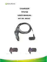
The DCS StarTac personal cellular telephone (shown on next
page, in Figure 3) is a microprocessor controlled, full duplex,
synthesized FM radiotelephone using digital modulation
techniques, for use in compatible 1800 MHz cellular
radiotelephone systems. When operated properly, the
equipment will provide the user with land-linked telephone
service through individual cell site base stations, all linked
to a central control office. The StarTac has a 1.0 Watt
maximum output power capability.
1.2 PHYSICAL PACKAGING
The transceiver circuitry is contained in a water resistant
polycarbonate plastic housing measuring 98.3 mm (L) x
57.3 mm (W) x 22.5 mm (D); with a capacity of less than
100cc at a weight of approximately 99.5g; including Slim
LiIon battery pack and antenna.
The main internal electronic circuitry is contained on two
multi-layer boards, the RF/Logic board, and the keyboard
assembly.
The keypad board assembly incorporates the display, keypad
contacts and LEDs. Electrical connections between the two
boards are provided by connectors at the lower end of each
board.
The RF/Logic board houses the RF and Audio/Logic
circuitry on separate sides in addition to SIM contacts, the
alert, a 16 position ZIF connector, the microphone, and an
external connector.
The accessory connector, situated at the base of the phone
on the main board, allows connections to the audio/logic
circuitry and antenna for accessory applications such as a
mobile adaptor and chargers. When the accessory RF
connector is used (ie terminated with a resistance of
approximately 10 Kohms or less to ground) the RF to the top
antenna is disconnected.
Operating power for the personal telephone can be obtained
from various methods including the following:-
Standard NiMH Battery pack
Standard Slim LiIon Battery pack
Standard XT LiIon Battery pack
Auxilliary NiMH Battery
The Auxilliary LiIon Battery
Rapid Charging Power Supplies
Cigarette Lighter Adaptors
The battery charger plugs into the accessory connector
socket, situated at the base of the telephone, and a vehicle’s
cigar lighter socket. As well as providing a battery charging
function, the adaptor provides power directly to the phone
whilst it is in use even with a ‘dead’ battery.
1/. Vehicle Adaptor Kits.
There will be a DHFA available which supports Hands Free
Operation, battery charging, automatic answering, ignition
sense, entertainment mute and auxilliary alert. The kit will
be compatible with ETACS StarTac but a separate hangup
cup will be necessary. It will accomodate an external
microphone and speaker, optional handset and the analogue
3 watt booster capability. The auxiliary battery cannot be
used with the DHFA. The vibra- alert is inactive when
phone is in use with the DHFA.
NOTE: The StarTac may have various battery options as
standard depending on the particular market requirements.

DCS 1800 StarTAC PERSONAL CELLULAR TELEPHONE
68P09304A85 BDesc2
6 19/07/97
EARPIECE
ANTENNA
KEYPAD
MICROPHONE
Figure 3. DCS StarTAC Personal Cellular Telephone.

Customer Services Publishing
Easter Inch, Bathgate, West Lothian
EH48 2EH, United Kingdom
BDesc2
© Motorola Ltd. 1997
All Rights Reserved
Printed in U.K.
DCS 1800 StarTAC PERSONAL
CELLULAR TELEPHONE
PRODUCT DESCRIPTION
FEATURE LIST
Cellular Subscriber Group
68P09304A85
19/07/97
7
An ‘X’ indicates that the feature is present in the StarTAC Personal Phone
FEATURE LIST PRESENT
VISUAL/AUDIO FEATURES
Display 32 X 96 Pixel
Graphics Display
Number Capacity (per location) 20
Name Capacity (per location) 16
Language Selection 14
Automatic Language Selection based on SIM X
Silence Ringer w/Visual X
Silence Keypad Tones X
Adjustable earpiece volume X
Adjustable ringer volume X
Silence Scratchpad X
Call in Absence Indicator X
Display Signal Strength - continuous X
Display Battery Level - continuous X
Audible Low Battery Warning X
Status Review X
Microphone Mute X
Illuminated Display X
Backlight Display X
Dedicated Control Keys 7
Operator Definable Wake Up Graphics X
Smart Button Operation X
Real Time Clock X
CALL PLACEMENT FEATURES
VibraCall Alert, Including Vibrate then Ring. X
Selectable Ringer Tones X
Selectable Keypad Tones X
Short, Extended and Personalised Menu List X
Auto Redial X
Clear Last Digit/All X
Mute Control X
International Access Key Sequence X
User Call Rejection X
Pre-origination Dialling X
FEATURE LIST PRESENT
Memories:
Numbered 100
SIM Card - Dependent on SIM X
Last 10 Numbers Dialed X
Last 10 Numbers Received (if using CLI) X
Notepad (Last Number Entered) X
Turbo Dialling (9 Numbers 1 Touch Dial)
from Phone and SIM X
Alpha Name Storage X
Recall by Name or Location X
Memory Linking/Pause X
Memory Auto Load X
Memory Scroll X
Alpha Name Scrolling X
Memory Capacity X
DTMF Signalling:
Long Tone DTMF X
DTMF from Memory X
Postscripting X
Menu Operation X
Silent Alert X
Call Diverting/Barring (Via the Menu) X
Calling Line Identification (Present and Restrict) X
Call Waiting X
Call Hold X
Master Clear X
Master Reset X
DTX (Discontinuous Transmission) X
112 Emergency Call Origination X
COST CONTROL FEATURES
Electronic Lock X
Automatic Lock X
Programmable Unlock Code X
Display Unlock Code X

DCS 1800 StarTAC PERSONAL CELLULAR TELEPHONE
68P09304A85 BDesc2
8 19/07/97
An ‘X’ indicates that the feature is present in the DCS 1800 StarTAC Personal Phone
FEATURE LIST PRESENT
COST CONTROL FEATURES (cont.)
Display Call Timers and/or Charge Meters:
Last Call X
Total X
Home X
Roam X
Programmable Audible Call Timer
One Time X
Repeatable (User Defined) X
Automatic Timer Display:
Charge (units/currency) X
Minutes X
Store Charge Rate:
Home Rate X
Roam Rate X
Call Restriction Levels:
Restrict Keypad Dialing X
Variable Memory Recall Restriction X
Restrict Incoming Calls X
Restrict Phone Number Length (Vari) X
Full Service-No Restrictions X
PIN Entry X
PIN Enable/Disable X
PIN Change X
PIN Unblocking X
NETWORK RELATED
Service Selection:
Auto PLMN Selection X
PLMN Select from Scan List X
Scan List Display (auto and manual) X
FEATURE LIST PRESENT
Change Preferred List X
Rearrange Order of Preferred List X
Full Size SIM card X
Display Own Phone Number X
MESSAGING AND DATA
SMS:
Mobile Originated X
Create/send/store/edit/view/delete X
Mobile Terminated Point to Point X
Cell Broadcast X
Data Calls X
VEHICULAR FEATURES
On Hook Call Processing X
Volume Adj-Speaker X
Safety Timer X
Full Duplex Hands Free Operation X
Ignition Sense (Auto Turn On) X
Entertainment Mute X
Auto Answer X
OTHER FEATURES
Status Indicators X
Easy Battery Removal X
Internal Charger X
Dead Battery Operation with Chargers X
Desktop Charger X
Cigarette Lighter Adaptor (Option) X
Auxiliary Battery X

Customer Services Publishing
Easter Inch, Bathgate, West Lothian
EH48 2EH, United Kingdom
CLbl3
© Motorola Ltd. 1997
All Rights Reserved
Printed in U.K.
DCS 1800 StarTAC
CELLULAR TELEPHONE
LABELLING AND SIM CARDS
TRANSCEIVER LABELLING
68P09304A85
19/07/97
9
Cellular Subscriber Group
TRANSCEIVER LABELLING
1. INTRODUCTION
Each Motorola DCS StarTAC transceiver will be labelled
with various number configurations. The following
information shows and explains the common labelling titles.
2. TITLE EXPLANATIONS
2.1 MSN
The Mechanical Serial Number (MSN) is an individual
number, uniquely identifying the unit. The MSN will remain
the same throughout the units life, even if the main board is
replaced. Because the MSN is unique to the whole phone, it
is often used for logging and tracking purposes by Motorola
National Service Centres on EPPRS. The MSN is divided
into the sections shown in Figure1.
2.2 CEPT DCS
This is the International Mobile Station Equipment Identity
(IMEI) number. The IMEI is held in the logic circuitry.
3 digits 1 digit 2 digits 4 digits
Model
Code
Origin
Code
Date
Code
Serial
Number
MSN 10 digits
Figure 1. MSN Configuration
MC
OC
DC SNR
If the main board is replaced then the units IMEI will change,
therefore the units labelling should be updated with the new
IMEI. An IMEI uniquely identifies a mobile station
equipment to the system, and is divided into the sections
shown in Figure 2.
2.3 REV S/H
This configuration consists of two blocks of two digits, and
denotes the software and hardware versions within the unit.
The first two digits correspond to the software version, and
the last two digits correspond to the hardware version. If a
version update is carried out on the unit, the corresponding
change information should be made apparent on the
labelling.
2.4 MODEL
The model number defines the type of product. Each product
type is issued a common model number.
2.5 PACKAGE
The package number is used to determine the type of
equipment, the mode in which it was sold, and the language
with which it was shipped.
6 digits 2 digits 6 digits 1 digit
TAC FAC
SNR
SP
Type
Approval
Code
Final
Assembly
Code
Serial
Number
Spare
IMEI 15 digits
Figure 2. IMEI Configuration

DCS 1800 StarTAC CELLULAR TELEPHONE
68P09304A85 CLbl3
10 19/07/97
*
PAGE INTENTIONALLY BLANK

Customer Services Publishing
Easter Inch, Bathgate, West Lothian
EH48 2EH, United Kingdom
CLbl3
© Motorola Ltd. 1997
All Rights Reserved
Printed in U.K.
DCS 1800 StarTAC PERSONAL
CELLULAR TELEPHONE
LABELLING AND SIM CARDS
Cellular Subscriber Group
68P09304A85
19/07/97
11
SIM CARDS
1. INTRODUCTION
The Motorola DCS StarTAC personal cellular telephones
are designed to work with the full size Subscriber Identity
Module (SIM). The SIM card contains all the personal data
required to access DCS services. Data held by the SIM card
includes:-
• International Mobile Subscriber Identity
• Temporary Mobile Subscriber Identity
• Home system
• Services subscribed to
• PIN and unblocking codes
• Call barring codes
The SIM card may also be capable of storing phone
numbers, names, and messages.
2. SIM CARD INSERTION/REMOVAL
The SIM card must be inserted into the unit correctly so that
the card can be read, and the data checked for validity,
before operation on the system will be enabled. The card
contains all of the user’s personal identification numbers
and details of the system the phone operates on.
The whole SIM card should slide completely into the slot at
the base of the phone. Ensure that the contacts of the card
face towards the front of the phone i.e. towards the keypad.
INTERFACE
CONTACTS
TEST SIM CARD
SIM CARD SLOT
Figure 1. Inserting the Test SIM card
The sliding, card release button will move upwards as the
SIM card is inserted. When the button reaches the top of its
recess and the card is flush with the base of the phone, it is
inserted correctly. To remove the SIM card from the unit,
push the sliding SIM card release button downwards. The
card will then be pushed out far enough to allow complete
removal. The User Guide contains full information about
inserting and removing the SIM card.
3. SECURITY INFORMATION
To stop unauthorized personnel using your SIM card, the
option of using a Personal Identity Number (PIN) is
available. When enabled the option requires (on power up) a
verification number to be entered via the unit’s keypad,
before the card can be used. Three attempts to enter the
correct PIN may be made. If after the three entries the correct
PIN has not been entered, the card becomes blocked. To
unblock the card an unblocking/super PIN code must be
entered. Ten attempts to enter the correct unblocking code
are permitted, if after ten attempts the correct code has not
been entered, the SIM card is corrupted and becomes useless.
Another option available for the SIM card is call barring. If
subscribed to, the call barring of incoming and/or outgoing
calls may be accomplished by entering a special key
sequence. The key sequence includes a “barring code”,
which determines the type of restriction incorporated, and a
password to validate the request. The initial password is
provided when you subscribe to the service. The password
can be changed by entering a set key sequence.
A valid standard sized SIM card can be used in any working
DCS transceiver, regardless of the manufacturer, which is
compatible with the standard size SIM card. To protect the
actual unit from unauthorized use, a lock function on the
hardware is available. When enabled, this function requires
that a three or four digit unlock code be entered, via the unit’s
keypad, before normal operation of the transceiver can take
place. The lock code can be changed by entering a set key
sequence.
Note: Further information on set key sequences can be
derived from the unit’s user guide.

DCS 1800 StarTAC CELLULAR TELEPHONE
68P09304A85 CLbl3
12 19/07/97
*
PAGE INTENTIONALLY BLANK
/