Page is loading ...

Page | 1

Page | 2
Contents
1. Preface .................................................................................................................................................. 3
2. Safety Precautions ................................................................................................................................. 4
3. Specifications ......................................................................................................................................... 7
3.1 Appearance and Structure of the Unit ............................................................................................ 7
3.2 Unit Data ........................................................................................................................................ 8
3.3 Unit Dimensions ............................................................................................................................. 9
4. Installation ............................................................................................................................................11
4.1 Application of Heat Pump for Cooling ............................................................................................11
4.2 Choosing the Right Unit .................................................................................................................12
4.3 Installation Location ......................................................................................................................12
4.4 Installation Method .......................................................................................................................13
4.5 Water Loop Connection .................................................................................................................13
4.6 Power Supply Connection ..............................................................................................................13
4.7 Transit ...........................................................................................................................................14
4.8 Inspection Before Trial Running .....................................................................................................14
4.9 Trial Running .................................................................................................................................14
5. Use & Operation of the Controller .........................................................................................................15
5.1 Main Interface Display and Function ...................................................................................................15
5.1.1 Power on interface .......................................................................................................................15
5.1.2 Starting up interface .....................................................................................................................15
5.1.3 Turning On & Off ..........................................................................................................................17
5.1.4 Mode Switch ................................................................................................................................17
5.1.5 Setting Target Temperature ..........................................................................................................18
5.1.6 Target Temperature Keyboard ......................................................................................................19
5.1.7 Fast Heating .................................................................................................................................20
5.1.8 Timer Setting ................................................................................................................................20
5.1.9 Setup Interface .............................................................................................................................21
5.1.10 Setting the Time .........................................................................................................................22
5.1.11 Fault Interface ............................................................................................................................23
5.1.12 Colour Display Calibration...........................................................................................................23
5.2 Parameter List and Breakdown Table ..................................................................................................24
5.2.1 Electronic Control Fault Table .......................................................................................................24
5.2.2 Parameter List ..............................................................................................................................25
5.3 Interface Drawing................................................................................................................................26
5.3.1 Controller Interface Diagram and Definition .................................................................................26
6. Troubleshooting ....................................................................................................................................28
7. Appendix...............................................................................................................................................29
7.1 Install Sketch Map ...............................................................................................................................29
7.2 Installation Explanation: Automatic Filled-Water .................................................................................30
7.3 Installation Explanation: Leakage Pressure Valve .................................................................................31
7.4 Assistant Heat Source Connection .......................................................................................................31
7.5 Caution and Warnings .........................................................................................................................32
7.6 Cable Specification ..............................................................................................................................33

Page | 3
1. Preface
To provide our customers with quality, reliability and versatility, this product has been made to strict
production standards. This manual includes all the necessary information about installation, debugging,
discharging and maintenance. Please read this manual carefully before you open or maintain the unit. The
manufacturer of this product will not be held responsible if someone is injured or the unit is damaged as a
result of improper installation, debugging, or unnecessary maintenance. It is vital that the instructions within
this manual are always adhered to. The unit must be installed by qualified personnel.
• The unit can only be repaired by a qualified installer centre, personnel or an authorised dealer.
• Maintenance and operation must be carried out according to the recommended time and
frequencies, as stated in this manual.
• Use genuine standard spare parts only.
• Failure to comply with these recommendations will invalidate the warranty.
The Evo Flex is a high efficiency, energy saving and environmentally friendly unit which is mainly used for
house warming. It can work with any kind of indoor unit such as a fan coil, radiator or floor heating pipe. A
single command heat pump can provide the heating and cooling capacity for multiple other indoor units. The
Evo Flex unit is designed to have heat recovery by using a super heater which can provide hot water for
sanitary purposes.
This series of heat pump unit owns following features:
Advanced Controlling
The PC microcomputer-based controller is available for the users to review or set the
running parameters of the heat pump. Centralized controlling system can control several units by PC.
Nice Appearance
The heat pump is designed to be aesthetically pleasing. The water pump included which is very easy for
installation.
Flexible Installation
The unit has a smart structure with compact body, only a simple outdoor installation is needed.
Quiet Operation
A high quality and efficient compressor, fan and water pump are used to ensure a low noise level.
Good Heat Exchange Rate
The heat pump unit uses a specially designed heat exchanger to enhance the efficiency.
Large Working Range
This series of heat pump is designed to work under different working conditions as low
as -15 degrees for heating.

Page | 4
2. Safety Precautions

Page | 5

Page | 6

Page | 7
3. Specifications
3.1 Appearance and Structure of the Unit
Evo Flex 10
Evo Flex 17 & 25

Page | 8
3.2 Unit Data
Model
Evo Flex
10
17
25
Cooling Capacity
kW
10
14.5
20
BTU/h
34121
49489
68260
Heating Capacity
kW
11.5
16.5
25
BTU/h
39240
56315
85325
Hot Water Capacity
kW
13.2
21.6
30
BTU/h
45040
73702
102364
Cooling Power Input
BTU/h
3.4
5.6
9.0
Heating Power Input
kW
3.4
5.1
9.0
Hot Water Power Input
BTU/h
3.6
6.2
8.2
Operation Electric Current (max)
kW
15.7
27
14.0
Cooling Capacity Range
kW
2.0 ~ 10
5.0 ~ 14.5
7.0 ~ 20.0
Heating Capacity Range
kW
2.5 ~ 11.5
5.0 ~ 16.5
8.0 ~ 25.0
Hot Water Capacity Range
A
4.2 ~ 13.2
7.4 ~ 21.6
11.0 ~ 30.0
Cooling Power Input Range
kW
1.0 ~ 3.4
1.6 ~ 5.6
2.5 ~ 9.0
Heating Power Input Range
kW
0.8 ~ 3.4
1.2 ~ 5.1
2.5 ~ 9.0
Hot Water Power Input Range
kW
1.0 ~ 3.6
1.5 ~ 6.2
2.1 ~ 8.2
Power Supply
230V~/50Hz
230V~/50Hz
380V/3N~/50Hz
Compressor Quantity
1
1
1
Compressor Model
Rotary
Rotary
Rotary
Fan Quantity
1
2
2
Fan Power Input
W
75
75 X 2
150 X 2
Fan Rotate Speed
RPM
850
850
900
Noise
dB(A)
54
58
62
Water Pump Input
kW
0.18
0.5
0.65
Water Head
m
12.5
21
22.5
Water Connection
inch
1
1 1/4
1 1/4
Water Flow Volume
m
3
/h
1.6
2.8
4.2
Water Pressure Drop (max)
kpa
24
105
71
Unit Net Dimensions (L/W/H)
mm
953*445*910
996*395*1320
1175*400*1592
Unit Shipping Dimensions (L/W/H)
mm
1040*490*920
1070*435*1340
1225*430*1600
Net Weight
kg
See Nameplate
See Nameplate
See Nameplate
Shipping Weight
kg
See Package
Label
See Package Label
See Package Label
Cooling Working Condition: (DB/WB)35°C/24°C, (outlet/inlet) 7°C/12°C
Heating Working Condition: (DB/WB) 7°C/6°C, (outlet/inlet) 35°C/30°C
Hot Water Working Condition: (DB/WB) 20°C/15°C, (outlet/inlet) 40°C/45°C
BS EN 14511-1-2013 Air Conditioner, whole liquid cooling machine, electric compressor.
Part 2: Test condition Part 3: Test Method Part 4: Related requirements.

Page | 9
3.3 Unit Dimensions
Evo Flex 10
Evo Flex 17

Page | 10
Evo Flex 25

Page | 11
4. Installation
4.1 Application of Heat Pump for Cooling

Page | 12
4.2 Choosing the Right Unit
Based on the local climate conditions, construction features and insulation level, calculate the required
cooling (heating) capacity per square meter.
Conclude the total capacity which will be needed by the construction.
According to the total capacity needed, choose the right model by consulting the heat pump features as
below:
Heat Pump Features
Cooling Only Unit: chilled water outlet temp. at 5-15°C, maximum ambient temp. at 43°C
Heating and Cooling Unit: for cooling chilled water outlet temp. at 5-15°C, maximum ambient temp. at 43°C.
For heating warm water inlet temp. at 40-50°C, minimum ambient temp. at -10°C.
Unit Application
The Evo Flex can be installed in houses, offices, hotels and many more locations which require heating and
cooling separating, with each area needing to be controlled independently.
4.3 Installation Location
• The unit can be installed in any place outdoors which will be able to support the weight of a heavy
unit such as a terrace, roof, the ground and any other places deemed suitable.
• The location must have good ventilation.
• The location must be free from heat radiation and other fire hazards.
• A pall is needed in winter to protect the unit from snow.
• There must be no obstacles near the inlet and outlet of the unit.
• The installation location must be protected from strong winds or air.
• There must be a water channel around the heat pump to drain condensing water.
• Leave enough space around the unit for maintenance.

Page | 13
4.4 Installation Method
The heat pump can be installed onto the concrete basement by using expansion screws, or onto a steel
frame with rubber feet which can be placed on the ground or the roof. Ensure that the unit is placed
horizontally.
4.5 Water Loop Connection
Please pay attention to the below matters when the water pipe is connected.
• Try to reduce the resistance to the water from the piping.
• The piping must be clear and free from dirt and blockage. A water leakage test must be carried out
to ensure that there is no water leaking before the installation can be made.
• The pipe must be tested by pressure separately. DO NOT test it together with the unit.
• There must be an expansion tank on the top point of the water loop, and the water level inside the
tank must be at least 0.5meters higher than the top point of the water loop.
• The flow switch is installed inside of the heat pump, check to ensure that the wiring and action of
the switch is normal and controlled by the controller.
• Try to avoid any air from being trapped inside the water pipe, there must be an air vent on the top
point of the water loop.
• There must be a thermometer and pressure meter at the water inlet and outlet for easy inspection
during running.
4.6 Power Supply Connection
• Open the front panel and open the power supply access.
• The power supply must go through the wire access and be connected to the power supply terminals
in the controlling box. Then connect the 3-signal wire plugs of the wire controller and main
controller.
• If an external water pump is required, please insert the power supply wire into the wire access and
connect it to the water pump terminals.
• If an additional auxiliary heater is needed to be controlled by the heat pump controller, the relay (or
power) of the aux-heater must be connected to the relevant output of the controller.

Page | 14
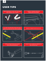
4.7 Transit
If the unit needs to be hung up during installation, an 8-metre cable is
required. There must be a soft material between the cable and the unit to
prevent damage to the heat pump cabinet (see picture 1).
WARNING
DO NOT touch the heat exchanger of the heat pump with fingers or other
objects!
4.8 Inspection Before Trial Running
Inspection before trial running
• Check the indoor unit, make sure that the pipe connection is done correctly, and the relevant valves are
open.
• Check the water loop to ensure that the water inside of the expansion tank is filled to an appropriate
level, and the water supply is working, and the water loop is full of water and free of trapped air. Make
sure there is good insulation for the water pipe.
• Check the electrical wiring. Make sure that the power voltage is normal, the screws are fastened, the
wiring is made in line with the diagram and that the earthing is connected.
• Check that the heat pump includes all the screws and components, and that they are in good order.
When powering the unit on, review the indicator on the controller to see if there is any indication of
failure. The gas gauge can be connected to the check valve to see the high pressure (or low pressure) of
the system during trial running.
4.9 Trial Running
• Start the heat pump by pressing the ‘POWER’ button key on the controller. Check whether the water
pump is running, if it runs normally there will be 0.2MPa on the water pressure meter.
• When the water pump has ran for a minute, the compressor will start. Listen for any strange sounds
from the compressor, if an abnormal sound occurs please stop the unit and check the compressor. If the
compressor runs well please look for the pressure meter of the refrigerant.
• Check whether the power input and running current is in line with the manual. If not please stop and
check.
• Adjust the valved on the water loop to make sure that the hot (cool) water supply to each door is good
and meets the requirements of heating (or cooling).
• Review whether the outlet water temperature is stable.
• The parameters of the controller are set by the factory, the user cannot change these themselves.

Page | 15
5. Use & Operation of the Controller
5.1 Main Interface Display and Function
5.1.1 Power on interface
5.1.2 Starting up interface

Page | 16
Key Functions
Key No.
Key Name
Key Function
1
On and off
Click this key to switch ON or OFF
Red represents ON, while grey represents OFF
2
Mode key
Hot water mode, heating mode, cooling mode, hot water + heating
mode or hot water + cooling mode can be selected by pressing this key
3
Temperature setting
Click this to set the target temperature
4
Fast heating
Click this key to start rapid heating
This key will be displayed during heating
5
Timer setting
Click this key to set the timer. White represents not enabled, while
green represents enabled
6
Setup key
Click this key to check the unit status, time, factory parameters,
temperature curve, timer setting and mute setting
7
Fault icon
This icon will flash when there is an error occurring, then the display
will enter the failure record interface after tapping this icon
Note:
8 is the defrosting icon, the machine is in defrosting mode when this icon is shown
9 is the hot water mode icon, this machine is in hot water mode then this icon is shown
10 is the heating mode icon, this machine is in heating mode when this icon is displayed

Page | 17
5.1.3 Turning On & Off
As the main interface shows
1. In the shut-down interface (on/off key will be in grey), press the on/off key to start the unit
2. In the starting-up interface (on/off key will be red), pressing on/off will turn the unit off
5.1.4 Mode Switch
In the main interface, there are five modes that can be selected after tapping the mode key:
Note: If you have purchased a heating-only model (with no cooling functions), “cooling” mode will not appear

Page | 18
5.1.5 Setting Target Temperature
Pressing (1) will bring the controller back to the main interface
Pressing (2) will allow the target temperature to be set, a pop-up keyboard will appear
Pressing (3) will allow the target temperature of cooling mode to be set through the keyboard

Page | 19
5.1.6 Target Temperature Keyboard
When the target temperature is being set, the following keyboard will appear
Key No.
Key Name
Key Function
2
Return Key
This key will return you to the main interface
3
Delete Key
This key will undo your last action
4
Enter Key
This key allows you to save your changes and return to the menu
Note: (1) means the new target temperature under the current settings

Page | 20
5.1.7 Fast Heating
Under heating mode, click the fast heating key (1) and the following interface will appear. Click (2) to start
fast-heating mode and (3) to close it.
5.1.8 Timer Setting
Click the timer setting key to enter the timer settings and the following interface will appear
/