RAB Lighting FFLED52SF USA Operating instructions
- Category
- Motorcycle Accessories
- Type
- Operating instructions

INSTRUCTIONS
FFLED INSTALLATION
RAB Lighting is committed to creating high-quality, aordable, well-designed and energy-ecient LED lighting and controls that make it easy for electricians to install
and end users to save energy. We’d love to hear your comments. Please call the Marketing Department at 888-RAB-1000 or email: [email protected]
IMPORTANT
READ CAREFULLY BEFORE INSTALLING FIXTURE. RETAIN THESE INSTRUCTIONS FOR FUTURE REFERENCE.
RAB xtures must be wired in accordance with the National Electrical Code and all applicable local codes. Proper grounding is
required for safety. THIS PRODUCT MUST BE INSTALLED IN ACCORDANCE WITH THE APPLICABLE INSTALLATION CODE BY A PERSON
FAMILIAR WITH THE CONSTRUCTION AND OPERATION OF THE PRODUCT AND THE HAZARDS INVOLVED.
WARNING: Make certain power is OFF before installing the xture. No user serviceable parts inside.
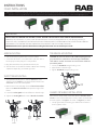
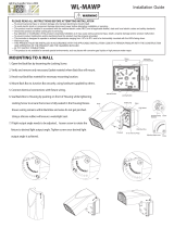
ARM MOUNTING
SLIPFITTER MOUNTING
1. Seal arm thread using Teon tape or silicone sealant.
2. Secure the LED ood to a 1/2” NPS hole in a junction box or
landscape post. Heavy duty XC1 cover provided.
3. Plug all unused holes and seal threads with silicone.
4. The swivel arm on the LED ood allows 180° of vertical aiming
adjustment depending on mounting location.
1. The sliptter mounting ts a 2 3/8” O.D. Tenon. Place the
sliptter over the Tenon and secure the xture with the two
Set Screws on the side of the sliptter.
2. Remove two screws and plug on side of Round Cover Plate.
Remove the Round Cover Plate and adjust the angle of the
xture.
3. Loosen the Locking Bolt and swivel xture to desired angle.
4. Tighten the Locking Bolt and re-attach Round Cover Plate.
TRUNNION MOUNTING
GUARD OR SHIELD INSTALLATION
CAUTION: UL and C-UL listed or CSA certied liquid tight cord
grip suitable for use with three conductor type STW exible
cord shall be used for connection to a wet location outlet box
provided by others.
1. Loosen the Pivot Bolts & angle locking screw.
2. Adjust xture to desired angle.
3. Tighten Pivot Bolts & angle locking screw.
Wire Guard and Poly Shield mount with (4) #8-32 Stainless Steel
Screws. Screws are provided with accessory. Guard and Shield may
be used together. See Figure 1 for Guard. See Figure 2 for Shield.
1. Line up guard with pre-existing, pre-drilled holes in frame as
shown, tighten screws.
Fig. 1
Fig. 2
Set Screws
Tennon
Round
Cover
Plate
Locking
Bolt
Pivot
Bolts

INSTRUCTIONS
FFLED INSTALLATION
RAB Lighting is committed to creating high-quality, aordable, well-designed and energy-ecient LED lighting and controls that make it easy for electricians to install
and end users to save energy. We’d love to hear your comments. Please call the Marketing Department at 888-RAB-1000 or email: [email protected]
CLEANING & MAINTENANCE
ACCESSORIES & REPLACEMENT PARTS
TROUBLESHOOTING
Note: These instructions do not cover all details or variations in equipment nor do they provide for every possible situation during installation, operation or maintenance.
CAUTION: Be sure xture temperature is cool enough to touch.
Do not clean or maintain while xture is energized.
1. Clean glass lens with non-abrasive glass cleaning solution.
2. Do not open the xture to clean the LED. Do not touch the LED.
Chrome Wire Guard: GDFFLED39W
Poly Shield: GDFFLED39P
Lens & Door Replacement: LFFLED39 (bronze)
LFFLED39W (white)
1. Check that the line voltage at the xture is correct. Refer to
wiring directions.
2. Be sure the xture is grounded properly.
3. Is the photocell, if used, functioning properly?
FFLED26-39-52-80-IN 0720
Easy Answers
rablighting.com
Visit our website for product info
Tech Help Line
Call our experts: 888 722-1000
e-mail
Answered promptly - [email protected]
Free Lighting Layouts
Answered online or by request
© 2020 RAB LIGHTING Inc.
Northvale, New Jersey 07647 USA
RAB WARRANTY: RAB’s warranty is subject to all terms and conditions found at rablighting.com/warranty.
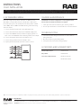
010V DIMMABLE WIRING
Universal voltage driver permits operation at 120V thru 277V,
50 or 60 Hz., except xtures factory ordered with a 120V swivel
photocell (/PCS) and 277V swivel photocell (/PCS2). Units ordered
with (/480V) sux are 480V. For 0-10V dimming, follow the wiring
directions below:
1. Connect the black xture lead to the LINE supply lead.
2. Connect the white xture lead to the COMMON supply lead.
3. Connect the GROUND wire from xture to supply ground. Do
NOT connect the GROUND of the dimming xture to the output.
4. Connect the purple xture lead to the DIM V+ lead.
5. Connect the gray xture lead to the DIM V- lead.
6. Cap the yellow xture lead, if present. Do NOT connect.
73107-RAB
-
 1
1
-
 2
2


RAB Lighting FFLED52SF USA Operating instructions
- Category
- Motorcycle Accessories
- Type
- Operating instructions
Ask a question and I''ll find the answer in the document
Finding information in a document is now easier with AI
Related papers
-
RAB Lighting GDFFLED39W Operating instructions
-
RAB Lighting FXLED105TYW/LC Operating instructions
-
RAB Lighting PIPXL100SFNW/D10 Operating instructions
-
RAB Lighting IVAT3-75LPA740ZU Operating instructions
-
RAB Lighting FFLED120SFYW/D10/7PR Operating instructions
-
RAB Lighting CDLED6WD-26W-80D935-S Operating instructions
-
RAB Lighting FXLED78SFYW/BL Operating instructions
-
RAB Lighting FXLED300SFNB55W/PCT Operating instructions
-
RAB Lighting ALED2T125NRG/PCS2 Operating instructions
-
RAB Lighting CANVAS78SF/D10 Operating instructions
Other documents
-
 LEDone LOD-MWP HLV2 Series Installation guide
-
RAB A17 Operating instructions
-
 Lumight L-AS40-4UD-P-KN-Z Installation guide
-
 Lumight L-AS20-4UD-P-KN-Z Installation guide
-
RAB PARK34 Operating instructions
-
RAB GDX17-205 Operating instructions
-
 WAREHOUSE-LIGHTING COM WL-MAWP WareLight Mini Adjustable Wall Pack Installation guide
-
RAB A17 FA User manual
-
RAB FFLEDLSFW Operating instructions
-


