RAB Lighting STL200W Operating instructions
- Type
- Operating instructions

STL200/277 Installation Manual
STEALTH
STL200/277
Specications:
Switching Capacity:
Voltage:
Detection Pattern:
Time Adjustment:
Power Consumption:
Surge Protection:
UL Listing:
8 amps
277 volts
1000 watts incandescent
50’ x 200°
5 seconds to 12 minutes
1 watt
I.E.C. specs
Raintight Photoelectric Switch

1
CAUTIONS:
TURN OFF ALL POWER AT CIRCUIT BREAKER/FUSE PANEL.
• Read entire Installation Manual before proceeding.
• All wiring should comply with local electrical codes and
requires a qualied electrician
• The total lighting load connected to a STEALTH must not exceed 8
amps (1000 watts incandescent). To switch more wattage an electrician
can install a relay.
• Line Carrier Remote Control Systems such as X-10, Levitron or Radio
Shack are incompatible with sensors and cause false activations.
• Do not install sensors on a circuit that feeds motor loads like kitchen
appliances, HVAC equiptment, washer/dryer, or garagedoor openers.
• Sensor must be below and as far as possible away from lights.
• Sensor functions best when the direction of expected
movement is across its detection pattern, not towards the sensor.
• Mount 6-12 feet high for optimum range and detection.
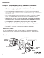
Mounting Plate:
STL200 Floodlight kits come with the RAB CU4 EZ plate, allowing for
mounting on round, rectangular or octogonal surface or recessed box.
Mounting
Bar Screws
Universal
Mounting
Bar
Hook
Gasket
Insert close-up plugs
in unused holes
Finishing
Cap
Center
Screw
O-Ring
Gasket
CU4 EZ Plate

2
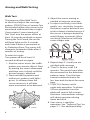
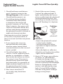
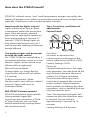
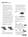
How does the STEALTH work?
STEALTH’s infrared sensor “sees” small temperature changes caused by the
motion of people or cars within its protection zone and turns on lights auto-
matically. It welcomes visitors and may deter intruders.
How long do the lights stay on?
Lights remain on as long as there
is movement within the protection
zone. Once the zone is vacated,
lights can be adjusted to remain on
from approximately 5 seconds-12
minutes. STEALTH keeps lights on
only when needed and uses just 1
watt to operate, making it extremely
energy ecient.
Can outdoor lights still be turned
on with the light switch?
Yes, STEALTH can be controlled by a
conventional indoor switch or circuit
breaker. Lights can be turned on or
o manually at night only.
Manual Override Mode:
To keep lights on, slowly ip the
switch twice (o-on-o-on) within
2-3 seconds.
To Resume Automatic Mode:
Flip the switch once (o-on) within 2
seconds. Sensor will reset to
Automatic Mode.
Will STEALTH detect animals?
STEALTH may detect large animals.
Having animal trigger the
sensor can give properties a “lived-
in” look. However, you can limit
animal detection by turning down
the sensitivity knob.
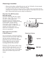
Sensitivity:
Increases or decreases the
responsiveness and range of the
sensor. Adjusts from 30% to 100%.
Factory Setting=100%.
Photocell:
Located behind the lens. For night-
only operation, turn the knob all the
way clockwise towards the moon
symbol. For 24-hour operation,
turn the knob all the way coun-
terclockwise towards the sun and
moon symbols. Adjust between
both symbols accordingly for other
operations, such as towards (but not
on) the moon for dusk.
Time: Sets the time that lights will
remain on after the detection zone
is vacated. Can be set from
approximately 5 seconds to 12
minutes.
Factory Setting=5-8 minutes.
Time, Sensitivity, and Photocell
adjustments
Control Panel:

3
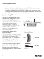
Choosing a Location
• Choose a location so that the sensor can “see” all paths of movement.
• The sensor may be wall or ceiling mounted.
• As distance from the sensor increases, it takes more movement to be
detected. For example: a half-step will register at ten feet, but not at 40
feet. 40 feet will need several steps for detection.
How does the LED Detection
Indicator work?
The red LED above the lens shows
the logic state of the sensor. If the
sensor is set for night-only
operation, the LED will go on for
daytime detections without turning
on the lights. Except during
detections, which trigger the
controlled lights, at night the LED
remains on and serves as a
deterrent, indicating a security
device in operation.
Red LED Detection Indicator
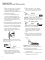
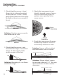
How large of an area does
STEALTH detect?
The standard lens detection pattern
extends out 50’ and is 200° wide. The
sensor may be swiveled in any
direction to cover the area desired.
Always keep the sensor level to
ensure full coverage. To reduce
coverage tilt the sensor down.
STEALTH STL200 comes with a stan-
dard “Double Look Down” Lens. This
lens has one “Look Out” zone and
two “Look Down” zones for excellent
detection at both long and short
range.
Detection Pattern
100’
30’

4
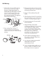
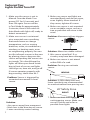
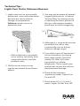
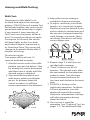
Kit Wiring
1. Attach the Universal Mounting
bar to the junction box with
the bar screws (provided). To
attach the STL200 kit to a surface
mount weatherproof box, you
must use the metal plate with
the attached gasket. The gasket
faces the junction box.
2. Easy wiring Tip: Use the “S”
shaped Hands-Free Hanging
Hook to hold the EZ Plate during
wiring.
Bar Screws
Universal
Mounting
Bar
Hook
Gasket
Insert close-up plugs
in unused holes
Finishing
Cap
Center
Screw
O-Ring
Gasket
CU4 EZ Plate
EZ Plate
3. Bring power leads and sensor kit
leads through holes in all gaskets
and into junction box.
4. Strip ½” of insulation from all
leads.
5. Attach ground wire(s) to junction
box grounding screw. Connect as
shown in wiring diagram (pg 5).
6. Twist on wire nuts. Secure with
electrical tape.
7. Align EZ Plate and metal
mounting plate to ensure proper
seal. Tighten EZ Plate center
screw to attach EZ Plate to box,
making sure O-Ring gasket is on
the screw. Two screws are
provided; use the one which
suits your assembly best.
8. Insert plastic Finishing Cap in
the center of the EZ Plate for a
weatherproof seal.
9. Use silicone sealant around all
openings to ensure a
weatherproof seal.
10. Screw in light bulbs and turn on
power. Conduct a Walk Test (pg
6) to adjust sensor response.

Multiple Fixtures
5
Black
Black
Red
Red
(pigtail)
Ground
Ground
Power In
White
White
Red pigtail only used to switch remote or additional xtures
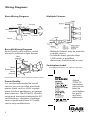
Wiring Diagrams
Basic Wiring Diagram
Power In
Sensor
Red
Black
White Ground
Basic Kit Wiring Diagram
Note: Pigtail is only used to switch
remote or additional light xtures.
• Multiple xtures may be wired to
a single sensor
• To handle loads greater than
1,000 watts, a qualied
electrician should install a relay.
Switchplate Label
Switchplate label has self-adhesive backing.
Power Quality
It is not recommended to install
sensors on a circuit that also feeds
motor loads such as HVAC equipt-
ment, kitchen appliances, or garage
door openers. The STEALTH circuit is
surge and transient protected to IEC
specications. However, if voltage
varies signicantly from 277 volts,
sensor may malfunction.
Attach
STEALTH
operating
instruction
label to
switchplate
for quick
and easy
reference.

6
Walk Test:
The purpose of the Walk Test is
to check and adjust the coverage
pattern. STEALTH has a 5 minute Test
Period which allows the sensor to be
aimed and walk-tested day or night.
If you require 5 more minutes of
Test Time, turn the power o for at
least 10 seconds and back on again.
During the Test Period, the sensor
will keep lights on for 5 seconds
each time it detects movement in
its Detection Zone. The sensor will
change to Automatic Mode after 5
minutes of testing.
To enter test mode:
Turn power o for at least 10
seconds and back on again.
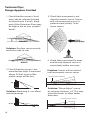
1. Aim the sensor across the trac
pattern you want to detect. Start
by aiming the sensor downward
and then raise it slowly until the
desired range is obtained.
2. Start outside the pattern and
walk across pattern until lights
go on. As distance from the
sensor increases, it will take
more movement to be detected.
Aiming and Walk Testing
Start Finish
3. Adjust the sensor aiming as
needed to improve coverage.
4. To adjust sensitivity, turn knob
gently. Less sensitivity (counter-
clockwise) may be desired if you
wish to detect a limited area or if
the sensor is being activated by
wind, foliage, or animals. More
sensitivity (clockwise) will help
cover a larger area.
5. Repeat steps 2-4 until you are
satised with coverage.
6. “Time” is factory set at 5-8
minutes. This period starts after
the movement in the detection
pattern ceases. Turn the time
control counterclockwise for
less time and clockwise for more
time.
7. STEALTH is factory set for
night-only operation. To obtain
24-hour operation, turn the
photocell control full counter-
clockwise. Intermediate settings
will adjust operation during
dawn and dusk.
8. Your sensor is ready for
operation. See “Technical Tips” on
pages 7-11 for additional help.

7
Technical Tips:
Lights Do Not Turn O
1. Make sure the sensor is not in
Manual Override Mode. Turn
power OFF for 10 seconds and
then ON again. Sensor will be
in Test Mode for approximately
5 minutes, then it will switch to
Auto Mode with lights o, ready to
detect movement.
2. Make sure sensor is not aimed
at or mounted over something
that would move or change
temperature, such as waving
branches, water, air conditioners,
windows or heating vents, even
on neighboring property.You can
test for infrared sources in the area
by placing a box or bag over the
sensor and putting the sensor into
test mode. This should keep the
lights o. Wave your hand inside
bag in front of sensor, and lights
should go on, time out, and go o.
If sensor operates properly with
bag covering, check item #4-7.
Problem: Sensor is triggered by
unwanted movement or heat
source.
Solution:
• Aim sensor away from movement
• Mask lens in the direction of source
• Lower sensitivity control setting
3. Make sure sensor and lights are
mounted rmly and do not move,
even slightly, when touched. If
they move, tighten all screws.
4. Make sure sensor is not mounted
on an unstable source, such as a
tree or pole that will move in the
wind.
Problem: Movement of tree triggers
sensor.
Solution: Mount on stable surface.
5. Was sensor wired hot? If so,
circuitry may have been damaged.
6. Make sure sensor is not aimed
within 20ft of a road.
Problem: Passing cars activate
sensor.
Solution: A 20ft safety zone and
lower sensitivity are recommended
to avoid activation from passing cars.
7. Make sure heat from lights is
not triggering sensor. Make sure
sensor is below and as far as
possible from lights.
RIGHT!WRONG!
20’ Safety Zone
RIGHT!
WRONG

8
Technical Tips:
Lights Turn On and O Incorrectly
1. Make sure the sensor is installed
on its own dedicated circuit, free
of motor loads such as HVAC
equiptment, kitchen appliances, or
garage door openers.
2. It is not recommended to wire
sensors in parallel. More than
one sensor wired together makes
them dicult to troubleshoot.
Disconnect multiple sensors and
test separately.
3. Keep all people completely out of
the detection pattern to make sure
the sensor is not detecting them.
4. Make sure sensor is located below
and as far as possible from its
lights. Heat from the lights may
trigger the sensor.
Solution: Move sensor below and
away from the lights. Do not use with
open par holders.
5. Moths can be attracted to the
lights and y close to the sensor
causing triggering. Reducing the
sensitivity may help.
6. Make sure sensor is not aimed
within 20 ft of a road or sidewalk.
Passing cars will activate sensor.
Solution: A 20ft safety zone and
reduced sensitivity are recommended
to avoid activation from passing cars.
7. Heavy rain, snow, or high
winds may activate the sensor
occaisionally. Reduce sensitivity
control slightly until problem
stops.
8. Make sure lights are not reecting
back into sensor. Check for white
or reective surfaces close to the
sensor.
Solution: Aim sensor away from
reective objects or move the objects
lower and reduce sensitivity.
9. Self-ballasted PL lamps may cause
cycling (on-o ).
10. Check item #2, 4, 5, 6 and 7 under
“If Lights Do Not Turn O.”
20’ Safety Zone
W
R
O
N
G
WRONG
RIGHT!
RIGHT!

9
Technical Tips:
Lights Do Not Turn On
Lights Turn O Too Quickly
1. Check that lamps and xtures
work. Compare wiring to the
Wiring Diagram in this manual.
Check that the power is on.
2. If installing during daylight,
remember that after power
is turned on, the sensor will
provide 5 minutes of Test Time.
After 5 minutes, the sensor will
switch to Automatic Mode and
will not work during daylight if
the photocell control is turned to
night-only (moon) position.
If you require more than 5 minutes
of Test Time, turn power o for at
least 10 seconds and then turn power
back on.
3. If you require the sensor to
operate both day and night,
turn the center control knob
counterclockwise to the sun and
moon symbol.
4. Check that lights from other
sources, such as adjacent porch,
garden, or streetlights, or lights
from inside the house, are not in
the sensor’s view. The sensor’s
photocell may detect the light
and deactivate. For operation at
higher ambient light levels, turn
the photocell control (center
knob) toward the sun symbol.
5. Was sensor wired hot? If
so, circuitry may have been
damaged.
1. Check if the sensor is being
“tricked” by reected light. If
lights controlled by the sensor
shine or reect into the photocell
(located behind the lens), the
unit will go on briey, but then
turn o, “thinking” it is daytime.
Solutions:
• Adjust the photocell control
(center knob) slightly
counterclockwise to allow
operation at higher ambient
light levels
• Move the lights or reectors
• Mask lens in the direction of the
lights and/or reections
2. Check if “R” lamps, non-reector
“A” lamps, or self-ballasted
PL lamps are being used in a
non-enclosed lampholder. If so,
switch to reector PAR oodlight
lamps or Quartz oods so the
sensor is not aected by stray
light. If using PAR oodlights,
consider using lower-wattage
energy-saving lamps.
Problem:
Light
shining or
reecting
directly
into
photocell

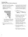
1. Check that the sensor is level
from side to side and pointed
at desired area. If unit is tilted,
part of the Detection Zone may
be high in the air over people’s
heads.
Solution: Position sensor exactly
level from side to side.
2. Check that the sensor is not
mounted too high. If mounted
above 20 feet, much of the
usable range will be lost.
Solution: Mounting 6-12ft allows
maximum range
Less
Sensitive
More
Sensitive
10
Technical Tips:
Range Appears Limited
WRONG!
RIGHT!
40’
20'
50’
6-12'
3. Check that movement is not
directly towards sensor. Sensor
will see movement across its
pattern more quickly. To x,
move sensor.
4. Check that movement far away
and directly towards sensor is
not entirely within one zone.
Problem: Sensor will not detect
until movement crosses zones.
No detection until here
PATHWAY
Solution: “Micro Adjust” sensor
by moving sideways 1/4”. This may
move the zones to allow earlier
detection.
Detection much sooner
PATHWAY

11
Technical Tips:
Lights Turn On for Unknown Reasons
1. Lights may turn on occasionally
during rain, snow and windstorms
because the sensor detects
changes in temperature.
Solution: mount sensor in
protected area.
• If false detections constantly
occur, reduce sensitivity (turn
counterclockwise) until the
problem stops.
2. Tilt the sensor lower; it may
register movement from distant
objects.
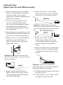
3. You may not be aware of animals
triggering the sensor. Create an
“Animal Alley” by aiming sensor
or masking the lower portion of
the lens with opaque weather-
proof tape to reduce triggering.
10’
50’
“Animal Alley”
4. Although it is surge and transient
protected, the sensor may
occasionally turn on during
extreme voltage surges.
5. A possible source of “mysterious”
sensor activations are strong
local radio signals. Check for
nearby CB, Ham, VHF radio
transmitters or cellular
telephones. These signals may
activate the sensor, but will not
do permanent damage.
6. Check all the solutions
mentioned under “Lights Turn
On and O.”
7. Check items #2, 4, 5, 6, and 7
under “Lights Do Not Turn O.”

12
Limited Warranty
Your STEALTH will be replaced or
repaired, at our option, if it proves
to be defective in worksmanship or
materials within ten years from the
date of original purchase.
For repair or replacement, return the
product, freight prepaid and insured,
to:
RAB Lighting
170 Ludlow Avenue
Northvale, NJ 07647
The STEALTH should be packed
carefully. Please include your sales
receipt and a description of the
problem.
If your unit is out of warranty or the
damage is unrelated to the
original manufacture, return your
unit directly to us with a check for
$30.00 (made out to RAB Lighting).
We will repair or replace your unit.
Under no circumstances shall we be
liable for any incidental or
consequential damages arising out
of or in connection with the use
or performance of this product or
other indirect damages with
respect to loss of property or
revenue or cost of installation,
removal or re-installation. This
warranty gives you specic legal
rights and you may also have other
rights which vary from state to
state.

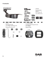
Contents:
13
• Crossbar with Green Ground
Screw
• Hanging Hook
• 1/2” Close Up Plugs (3)
• Slotted Screws (4)
• Finishing Cap
• O-ring Gasket
• Center Mounting Screws
• CU4 Plate
• Metal Plate
13
MetalCU4
STL200/277
• Indoor
Switchplate
Label
• Wire Nuts (3)
• Lens Mask (2)

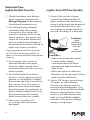
Easy Installation & Product Help
Tech Help Line
Call our experts 888 RAB-1000
©2016 RAB LIGHTING Inc.
Northvale, New Jersey 07647 USA
rabweb.com
Visit our website for product info
email
Answered promptly sales@rabweb.com
STL200/
277V
IN 1016

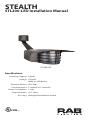
STL200-LED Installation Manual
STEALTH
STL200-LED
SUITABLE FOR WET LOCATIONS
Specications:
Switching Capacity:
Voltage:
Detection Pattern:
Time Adjustment:
Power Consumption:
Surge Protection:
UL Listing:
8 amps
120 volts
300W on LED xture
50’ x 200
5 seconds to 12 minutes
1 watt
I.E.C. specs
Raintight Photoelectric Switch

1
CAUTIONS:
TURN OFF ALL POWER AT CIRCUIT BREAKER/FUSE PANEL.
• Read entire Installation Manual before proceeding.
• All wiring should comply with local electrical codes and
requires a qualied electrician
• The total lighting load connected to a STEALTH must not exceed
8 amps (300W on LED xture). To switch more wattage an electrician
can install a relay.
• Line Carrier Remote Control Systems such as X-10, Levitron or Radio
Shack are incompatible with sensors and cause false activations.
• Do not install sensors on a circuit that feeds motor loads like kitchen
appliances, HVAC equiptment, washer/dryer, or garagedoor openers.
• Sensor must be below and as far as possible away from lights.
• Sensor functions best when the direction of expected
movement is across its detection pattern, not towards the sensor.
• Mount 6-12 feet high for optimum range and detection.

2
How does the STEALTH work?
STEALTH’s infrared sensor “sees” small temperature changes caused by the
motion of people or cars within its protection zone and turns on lights auto-
matically. It welcomes visitors and may deter intruders.
How long do the lights stay on?
Lights remain on as long as there
is movement within the protection
zone. Once the zone is vacated,
lights can be adjusted to remain on
from approximately 5 seconds-12
minutes. STEALTH keeps lights on
only when needed and uses just 1
watt to operate, making it extremely
energy ecient.
Can outdoor lights still be turned
on with the light switch?
Yes, STEALTH can be controlled by a
conventional indoor switch or circuit
breaker. Lights can be turned on or
o manually at night only.
Manual Override Mode:
To keep lights on, slowly ip the
switch twice (o-on-o-on) within
2-3 seconds.
To Resume Automatic Mode:
Flip the switch once (o-on) within 2
seconds. Sensor will reset to
Automatic Mode.
Will STEALTH detect animals?
STEALTH may detect large animals.
Having animal trigger the
sensor can give properties a “lived-
in” look. However, you can limit
animal detection by turning down
the sensitivity knob.
Sensitivity:
Increases or decreases the
responsiveness and range of the
sensor. Adjusts from 30% to 100%.
Factory Setting=100%.
Photocell:
Located behind the lens. For night-
only operation, turn the knob all the
way clockwise towards the moon
symbol. For 24-hour operation,
turn the knob all the way coun-
terclockwise towards the sun and
moon symbols. Adjust between
both symbols accordingly for other
operations, such as towards (but not
on) the moon for dusk.
Time: Sets the time that lights will
remain on after the detection zone
is vacated. Can be set from
approximately 5 seconds to 12
minutes.
Factory Setting=5-8 minutes.
Time, Sensitivity, and Photocell
adjustments
Control Panel:

3
Choosing a Location
• Choose a location so that the sensor can “see” all paths of movement.
• The sensor may be wall or ceiling mounted.
• As distance from the sensor increases, it takes more movement to be
detected. For example: a half-step will register at ten feet, but not at 40
feet. 40 feet will need several steps for detection.
How does the LED Detection
Indicator work?
The red LED above the lens shows
the logic state of the sensor. If the
sensor is set for night-only
operation, the LED will go on for
daytime detections without turning
on the lights. Except during
detections, which trigger the
controlled lights, at night the LED
remains on and serves as a
deterrent, indicating a security
device in operation.
Red LED Detection Indicator
How large of an area does
STEALTH detect?
The standard lens detection pattern
extends out 50’ and is 200° wide. The
sensor may be swiveled in any
direction to cover the area desired.
Always keep the sensor level to
ensure full coverage. To reduce
coverage tilt the sensor down.
STEALTH STL200-LED comes with a
standard “Double Look Down” Lens.
This lens has one “Look Out” zone
and two “Look Down” zones for
excellent detection at both long and
short range.
Detection Pattern
100’
30’

4
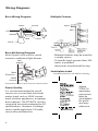
Multiple Fixtures
Black
Black
Red
Red
(pigtail)
Ground
Ground
Power In
White
White
Red pigtail only used to switch remote or additional xtures
Wiring Diagrams
Basic Wiring Diagram
Power In
Sensor
Red
Black
White Ground
Basic Kit Wiring Diagram
Note: Pigtail is only used to switch
remote or additional light xtures.
• Multiple xtures may be wired to
a single sensor
• To handle loads greater than 300
watts, a qualied
electrician should install a relay.
Switchplate Label
Switchplate label has self-adhesive backing.
Power Quality
It is not recommended to install
sensors on a circuit that also feeds
motor loads such as HVAC equipt-
ment, kitchen appliances, or garage
door openers. The STEALTH circuit is
surge and transient protected to IEC
specications. However, if voltage
varies signicantly from 120 volts,
sensor may malfunction.
Attach
STEALTH
operating
instruction
label to
switchplate
for quick
and easy
reference.
Page is loading ...
Page is loading ...
Page is loading ...
Page is loading ...
Page is loading ...
Page is loading ...
Page is loading ...
Page is loading ...
Page is loading ...
Page is loading ...
Page is loading ...
Page is loading ...
Page is loading ...
Page is loading ...
Page is loading ...
Page is loading ...
Page is loading ...
Page is loading ...
Page is loading ...
Page is loading ...
Page is loading ...
Page is loading ...
Page is loading ...
Page is loading ...
Page is loading ...
Page is loading ...
Page is loading ...
Page is loading ...
Page is loading ...
Page is loading ...
Page is loading ...
Page is loading ...
Page is loading ...
Page is loading ...
-
 1
1
-
 2
2
-
 3
3
-
 4
4
-
 5
5
-
 6
6
-
 7
7
-
 8
8
-
 9
9
-
 10
10
-
 11
11
-
 12
12
-
 13
13
-
 14
14
-
 15
15
-
 16
16
-
 17
17
-
 18
18
-
 19
19
-
 20
20
-
 21
21
-
 22
22
-
 23
23
-
 24
24
-
 25
25
-
 26
26
-
 27
27
-
 28
28
-
 29
29
-
 30
30
-
 31
31
-
 32
32
-
 33
33
-
 34
34
-
 35
35
-
 36
36
-
 37
37
-
 38
38
-
 39
39
-
 40
40
-
 41
41
-
 42
42
-
 43
43
-
 44
44
-
 45
45
-
 46
46
-
 47
47
-
 48
48
-
 49
49
-
 50
50
-
 51
51
-
 52
52
-
 53
53
-
 54
54


RAB Lighting STL200W Operating instructions
- Type
- Operating instructions
Ask a question and I''ll find the answer in the document
Finding information in a document is now easier with AI
Related papers
-
RAB Lighting STL200/240 Operating instructions
-
RAB Lighting STL110HB Operating instructions
-
-
RAB Lighting STL110-LED/277 Operating instructions
-
-
RAB Lighting STL360W Operating instructions
-
-
-
-
RAB Lighting BULLET2X12YB Operating instructions
Other documents
-
LNC 2I3YYRLWS411987 Dimensions Guide
-
RAB SNL1 Installation guide
-
Beyblade XTS Herculeo Defender A1753 Operating instructions
-
Havis C-LABEL-S Datasheet
-
Design House 514992 Installation guide
-
Universal Remote Control HE-117W User manual
-
Heath Zenith HZ-5311-BZ User guide
-
Ortech OD-PC User manual
-
Sharper Image 20036-107 Owner's manual
-