
INSTALLATION AND USE
Solution All-Fit
ARTICULATING ARM and
KEYBOARD PLATFORM
SOLUTION ALL-FIT Rev A 4/17
Model SOLUTION ALL-FIT
SOLUTION ALL-FIT

2
SOLUTION ALL-FIT
PLEASE REVIEW these instructions before beginning the installation. Check that
all parts needed were provided with your order. Contact your supplier if any
operates to your satisfaction.
Solution 1 combines the AA100 articulating arm with the PL003-27N keyboard
platform. In this instruction booklet, installation of the two products will be
explained in sequence, beginning with the AA100.
1
/2"
Drill 1
/8" Pilot Holes
Where Indicated
Underside of
Work Surface
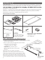
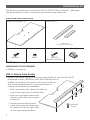
AA100 PARTS PROVIDED
Articulating Arm (1)
Front Stop (1) Track Extender (1) 5
/8" Wood
Screws (20*)
*Includes Extras
Track (1)
STEP 1: Drill Pilot Holes for Attaching Track
• Position one end of the track 1
/2" from the front edge
of the work surface.
• Drill 1
/8" pilot holes through the seven holes
indicated in the illustration.
— Drill the holes 5/8" deep.
CAUTION: Be careful not to
drill through the top of the work
surface.
With this short 13" track, the track
extender is normally used as the rear stop.
If the rear bumper will be used instead, drill a
pilot hole in the center rear hole through the
track into the bottom of the worksurface and
do not drill
pilot holes in the two rear side holes.
ADDITIONAL TOOLS REQUIRED
• Drill with 1
/8" bit
•#2 Phillips bit
Cord Clip (1)
CAUTION:
This install requires a
power drill. This is not
a hand tool install.
*Optional
Rear Bumper* (1)
Front
Rear
Optional Rear
Hole for Rear
Bumper.

AA100-PTLO ARTICULATING KEYBOARD ARM
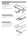
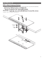
STEP 2: Attach Track
• First attach the track through the
four center holes, as shown.
• Then attach the track
extender through the two
rear holes.
• Do not attach a screw through
the front center hole at this time.
STEP 3: Install Articulating Arm
• Slide the articulating arm onto the track.
Position it back far enough so that you
have access to the front center hole
on the track.
STEP 4: Attach Front Stop
• Position the front stop onto the
front of the track and secure it with
a screw through the center hole.
• Drill pilot holes for the two side
screws and attach the ends of
the front stop with two more
screws.
Attach Through
Four Center Holes
Then Attach
Track Extender
Slide
Back
Front
Stop
3
Drill & Attach This
Screw First
Optional Rear Bumper
Placement

SOLUTION ALL-FIT
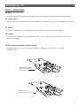
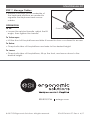
STEP 5: OPERATION
To Tilt:
• Loosen the ratchet handle, adjust the tilt angle, then tighten the handle.
To Telescope:
• Lift the front of the platform and slide it inward to stow or outward to access.
To Raise:
• Grasp both sides of the platform and raise to the desired height.
To Lower:
• Grasp both sides of the platform, tilt up the front, and move down to the
desired height.
To De-activate Positive Tilt Lock-out:
• Rotate tab turn to the right. Refer to diagrams below for further
explanation:
1
/4
TAB ROTATED UP
FOR NEGATIVE TILT ONLY
TAB ROTATED DOWN
FOR POSITIVE AND
NEGATIVE TILT
4

5
Panhead
Screw
The keyboard platform for Solution All-Fit is PL003-27N (notched). Although
the appearance varies, installation procedures are identical.
PL003-25N PARTS PROVIDED
Keyboard Platform (1) Palm Rest (1)
1 Each for
Keying and Mousing
Flathead Screw (4) Flange Nut (4) Cord Clips (2)Panhead Screw (4)
#8-32x1
/2#8x32 #8-32x5
/8
(R-Series: #8-32x3
/4)
CAUTION:
Hand-tighten screws only. Do not use power tools.
ADDITIONAL TOOLS REQUIRED
• Phillips screwdriver
STEP 5: Attach Palm Rest(s)
• Attach the palm rest(s) to the keyboard platform. Use the #8-32x5
/8
panhead screws (#8-32x3
/4 with the R-Series) and a
Phillips screwdriver. Six screw holes are located in
the keyboard platform to accommodate a
variety of installation possibilities.
— With one palm rest, attach it with two
screws through the two end holes.
— With two separate palm rests,
attach each with two screws,
as shown.
— The mouse and keyboard
palm rests may be attached
on either the left or right sides
of the keyboard platform.
SOLUTION ALL-FIT

6
STEP 6: Attach Keyboard Platform
• Attach the keyboard platform to the keyboard arm and track assembly
IMPORTANT:
locked. Use a Phillips screwdriver.
Flathead
Screw
Flange
Nut
Flathead
Screw
Flange
Nut
SOLUTION ALL-FIT

STEP 7: Manage Cables
• Adhere cord clips to the underside of
the keyboard platform as needed to
organize the keyboard and mouse
cables.
Cord Clip
OPERATION
To Tilt:
• Loosen the ratchet handle, adjust the tilt
angle, then tighten the handle.
To Telescope:
• Lift the front of the platform and slide it inward to stow or outward to access.
To Raise:
• Grasp both sides of the platform and raise to the desired height.
To Lower:
• Grasp both sides of the platform, tilt up the front, and move down to the
desired height.
800.833.3746 esiergo.com
© 2017 ESI Ergonomic Solutions. All rights reserved. SOLUTION ALL-FIT Rev A 4/17
SOLUTION ALL-FIT
-
 1
1
-
 2
2
-
 3
3
-
 4
4
-
 5
5
-
 6
6
-
 7
7


ESI AA100-PTLO Operating instructions
- Type
- Operating instructions
- This manual is also suitable for
Ask a question and I''ll find the answer in the document
Finding information in a document is now easier with AI
Related papers
Other documents
-
Eaton LMS Installation guide
-
 ESi Ergo AA355DS Assembly Instructions
-
Ergotron 97-053-002 User manual
-
-
JLG 740A Service And Maintenance Manual
-
-
-
-
Midmark Medical Lighting Installation guide
-
 EnovateIT E997 User manual

