Page is loading ...

INSTRUCTION MANUAL
INSTRUCTION MANUAL
• Be sure to read this Instruction Manual before using the product.
• Read the safety notes carefully.
• Keep this Instruction Manual in a safe and convenient place for future reference.
SM-A02367-A/5
MSV-484083
Electric Actuator
EKS Series
CKD Corporation

SM-A02367-A/5 PREFACE
i 2022-10-28
PREFACE
Thank you for purchasing CKD's "EKS Series" electric actuator. This Instruction Manual contains
basic matters such as installation and usage instructions in order to ensure optimal performance of the
product. Please read this Instruction Manual thoroughly and use the product properly.
Keep this Instruction Manual in a safe place and be careful not to lose it.
Product specifications and appearances presented in this Instruction Manual are subject to change
without notice.
CAUTION:
This product is not equipped with a motor.
You need to prepare, install, and adjust a motor and driver by yourself.
Make sure to install a motor properly in accordance with the instructions given in this Instruction
Manual.
For how to adjust a motor, refer to the instruction manual of the motor.

SM-A02367-A/5 SAFETY INFORMATION
ii 2022-10-28
SAFETY INFORMATION
When designing and manufacturing any device incorporating the product, the manufacturer has an ob-
ligation to ensure that the device is safe. To that end, make sure that the safety of the machine mecha-
nism of the device and the electric system that controls such mechanism is ensured.
In order to use our products safely, it is important to select, use, handle, and maintain the products
properly.
Observe the warnings and precautions described in this Instruction Manual to ensure device safety.
Although various safety measures have been adopted in the product, customer's improper handling may
lead to an accident. To avoid this:
Be sure to read this Instruction Manual thoroughly and understand its descriptions
before using the product.
To explicitly indicate the severity and likelihood of a potential harm or damage, precautions are classified
into three categories: "DANGER", "WARNING", and "CAUTION".
DANGER
Indicates an imminent hazard. Improper handling may cause death or serious
injury to people.
WARNING
Indicates a potential hazard. Improper handling may cause death or serious
injury to people.
CAUTION
Indicates a potential hazard. Improper handling may cause injury to people or
damage to property.
Some statements classified as "CAUTION" may still lead to serious results depending on the situation.
All statements that follow these labels are important and must be observed.
Other general precautions and tips on using the product are indicated by the following icon.
Indicates general precautions and tips on using the product.

SM-A02367-A/5 SAFETY INFORMATION
iii 2022-10-28
Precautions on Product Use
DANGER
Do not use the product for the following applications:
• Medical equipment pertaining to sustainment and management of human life and body
• Mechanism and mechanical device for conveyance and transportation of people
• Important safety part of a mechanical device
WARNING
Use the product within its specifications.
Precautions on Product Disposal
CAUTION
When disposing of the product, comply with laws pertaining to disposal and cleaning of
wastes, and have an industrial waste disposal company dispose of the product.

SM-A02367-A/5 CONTENTS
iv 2022-10-28
CONTENTS
PREFACE ........................................................................................................................... i
SAFETY INFORMATION .................................................................................................. ii
Precautions on Product Use .......................................................................................... iii
Precautions on Product Disposal .................................................................................. iii
CONTENTS ...................................................................................................................... iv
1. PRODUCT OVERVIEW ............................................................................................. 1
1.1 Part Name ........................................................................................................... 1
1.2 System Configurations ........................................................................................ 2
1.3 Model Number Indication .................................................................................... 3
1.3.1 Model number configuration ......................................................................... 3
1.3.2 Motor specifications ...................................................................................... 4
1.4 Specifications ...................................................................................................... 5
1.4.1 Product specifications (straight) ................................................................... 5
1.4.2 Product specifications (folding) .................................................................... 6
2. INSTALLATION ......................................................................................................... 7
2.1 Environment ........................................................................................................ 9
2.2 Unpacking ......................................................................................................... 10
2.2.1 Product list .................................................................................................. 10
2.3 Installing motor ...................................................................................................11
2.3.1 Straight type ................................................................................................ 11
2.3.2 Folding type ................................................................................................ 14
2.4 Installing option parts ........................................................................................ 22
2.4.1 Installing fittings .......................................................................................... 22
2.5 Installing main unit ............................................................................................ 23
2.5.1 Installation from top .................................................................................... 23
2.5.2 Installation from bottom .............................................................................. 27
2.5.3 Installing loaded object ............................................................................... 28
2.5.4 Positioning pin protrusion length ................................................................ 29
3. USAGE ..................................................................................................................... 30
3.1 Safety Instructions ............................................................................................ 30
3.2 Operation .......................................................................................................... 31
4. MAINTENANCE AND INSPECTION ....................................................................... 32
4.1 Periodic Inspection............................................................................................ 33
4.1.1 Inspection item ........................................................................................... 33
4.1.2 Recommended grease ............................................................................... 34
4.1.3 Recommended grease gun ........................................................................ 35
4.1.4 EKS Series lubrication procedure .............................................................. 36
4.1.5 How to replace steel belt ............................................................................ 40
5. WARRANTY............................................................................................................. 47
5.1 Warranty Provisions .......................................................................................... 47
5.2 Warranty Period ................................................................................................ 47

SM-A02367-A/5 1. PRODUCT OVERVIEW
1 2022-10-28
1. PRODUCT OVERVIEW
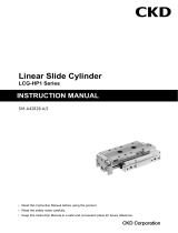
1.1 Part Name
Steel belt
Intermediate flange
Table cover
Table
Housing B cover
Outer rail
Side cover
Sensor
groove
Housing A cover
Guide block
Lubrication device
Folding cover
Motor mounting plate
Motor
Motor
Steel belt
Ball screw

SM-A02367-A/5 1. PRODUCT OVERVIEW
2 2022-10-28
1.2 System Configurations
Recommended servo motor network examples
General SSCNET CC-Link
MECHATRO
LINK-II
MECHATRO
LINK-III
Device
NET
Ether
CAT
Mitsubishi Electric Corporation
Delta Electronics, Inc.
SANYO Electric Co., Ltd.
YASKAWA Electric Corporation
KEYENCE CORPORATION
Panasonic Corporation
OMRON Corporation
This product is not equipped with a motor. A motor and driver must be prepared, installed, and adjusted by yourself.
PLC
Servo/Amplifier
EKS Series
Origin/limit sensor
Whether or not to install sensors can
be selected with a model number.
(Power/Control)
Power supply
(Control)
Power
supply
Motor installation method
The method can be selected from 4 types using a model number.
Straight installation
Right folding installation
Left folding installation
Under folding installation
Sensor dock
Sensors
Servo motor
(A servo motor must be prepared,
installed, and adjusted by yourself.)
(The devices and cables shown
above must be prepared by yourself.)

SM-A02367-A/5 1. PRODUCT OVERVIEW
3 2022-10-28
1.3 Model Number Indication
1.3.1 Model number configuration
Symbol Description
(A)Body size
04 Body width: 43mm
05 Body width: 52.6mm
06 Body width: 64mm
08 Body width: 84mm
10 Body width: 104mm
(B)Motor mounting direction
E Straight installation
R Right folding installation
L Left folding installation
D Under folding installation
(C)Screw lead
Body size
04 05 06 08 10
10 10mm ● ● ― ― ―
16 16mm ● ― ― ― ―
20 20mm ― ● ● ● ―
25 25mm ― ― ― ― ●
30 30mm ― ― ● ― ―
40 40mm ― ― ― ● ―
50 50mm ― ― ― ― ●
(D)Stroke
Body size
04 05 06 08 10
0100 100mm ● ● ● ● ●
Body size
:Body width 43mm
0200 200mm ● ● ● ● ●
:
Straight installation
0300 300mm ● ● ● ● ●
0400 400mm ● ● ● ● ●
Screw lead :10mm
0500 500mm ● ● ● ● ●
Stroke :200mm
0600 600mm ● ● ● ● ●
Motor specifications :Mitsubishi
0700 700mm ● ● ● ● ●
Motor size :
100W
0800 800mm ● ● ● ● ●
Motor axis fixing :In tha case of straight installation
0900 900mm ● ● ● ● ●
Orijin sensor
:With sensor
1000 1000mm ― ― ● ● ●
Limit sensor :With sensor
1100 1100mm ― ― ● ● ●
Anti-rust treatment
:With anti-rust treatment
1200 1200mm ― ― ● ● ●
Fitting :Without fitting
1300 1300mm ― ― ● ● ●
Optional specifications :
1400 1400mm ― ― ― ● ●
1500 1500mm ― ― ― ● ●
(E)Motor specifications
M
Y
P
(F)Motor size
Body size
04 05 06 08 10
H50W ● ― ― ― ―
1100W ● ● ― ― ―
2200W ― ― ● ― ―
4400W ― ― ― ● ―
8750W ― ― ― ― ●
(G)Motor axis fixing
Body size
04 05 06 08 10
D (※1) Flat face ● ● ● ― ―
K (※1) Key ● ● ● ― ―
M (※1)
Friction fastening
― ― ● ● ●
(H)Origin sensor
NWithout sensor *2
CWith sensor
(I)Limit sensor
NWithout sensor *2
BWith sensor
(J)Anti-rust treatment *5
NWithout anti-rust treatment
UWith anti-rust treatment *4
(K)Fitting *5
NWithout fitting
VWith fitting ※3
(L)Optional specifications *5
P4 For rechargeable battery manufacturing process
P40 For rechargeable battery manufacturing process *3
FP1 For food manufacturing processes
*1: Cannnot be selected in the case of straight installation.
*2: Origin sensor and limit sensor are a set.
Select "Without sensor" for both of them if selecting it for either.
*3: Cannnot be selected in the case of folding installation.
*4: Can only be selected in the case of optional specifications "P40".
*5: No symbol if no option is specified.
N
●
●
●
●
●
In the case of
straight
installation
For motor specifications, see the next page.
Symbol
Size
Symbol
Fixing
method
Motor mounting
direction
For rechargeable battery
manufacturing process
Symbol
Lead
<Example of model number indication>
Symbol
Length
EKS-04LE-100200NNN-M1NCB-UN-P40
―
―
―
0200
N
―
M
10
―
04
L
EKS
NN
E
N
C
B
1
N
U
P40
Model No.

SM-A02367-A/5 1. PRODUCT OVERVIEW
4 2022-10-28
1.3.2 Motor specifications
Symbol
Manufacturer name
Series
Model no.
50W
(EKS-04 Series)
100W
(EKS-04/05 Series)
M
Mitsubishi Electric Corporation
MELSERVO J3
HF-KP053
HF-KP13
MELSERVO J4
HG-KR053
HG-KR13
OMRON Corporation
G5
R88M-K05030
R88M-K10030
1S
-
R88M-1M10030
SANYO Electric Co., Ltd.
SANMOTION R
R2 A04005 *1
R2 A04010 *1
Tamagawa Seiki Co., Ltd.
TBL-i II
TS4602
TS4603
TBL-i IV
TSM3102
TSM3104
Fanuc Corporation
is series
is0.2/5000
is0.3/5000
Delta Electronics, Inc.
ECMA-C
ECMA-C1040F
ECMA-C10401
Y
YASKAWA Electric Corporation
-V
SGMJV-A5
SGMJV-01
-7
SGM7J-A5
SGM7J-01
KEYENCE CORPORATION
SV
SV-M005
SV-M010
SV2
SV2-M005
SV2-M010
P
Panasonic Corporation
MINAS A5
MSMD5A
MSMD01
MINAS A6
MSMF5A
MSMF01
*1: Folding installation is not supported.
Symbol
Manufacturer name
Series
Model no.
200W
(EKS-06 Series)
400W
(EKS-08 Series)
M
Mitsubishi Electric Corporation
MELSERVO J3
HF-KP23
HF-KP43
MELSERVO J4
HG-KR23
HG-KR43
SANYO Electric Co., Ltd.
SANMOTION R
R2 A06020
R2 A06040
Tamagawa Seiki Co., Ltd.
TBL-i II
TS4607
TS4609
TBL-i IV
TSM3202
TSM3204
Delta Electronics, Inc.
ECMA-C
ECMA-C10602
ECMA-C10604
Y
YASKAWA Electric Corporation
-V
SGMJV-02
SGMJV-04
-7
SGM7J-02
SGM7J-04
KEYENCE CORPORATION
SV
SV-M020
SV-M040
SV2
SV2-M020
SV2-M040
P
Panasonic Corporation
MINAS A5
MSMD02
MSMD04
MINAS A6
MSMF02
MSMF04
OMRON Corporation
G5
R88M-K20030
R88M-K40030
1S
R88M-1M20030
R88M-1M40030
Symbol
Manufacturer name
Series
Model no.
750W
(EKS-10 Series)
M
Mitsubishi Electric Corporation
MELSERVO J3
HF-KP73
MELSERVO J4
HG-KR73
Tamagawa Seiki Co., Ltd.
TBL-i II
TS4614
TBL-i IV
TSM3304
Delta Electronics, Inc.
ECMA-C
ECMA-C10807
Y
YASKAWA Electric Corporation
-V
SGMJV-08
-7
SGM7J-08
KEYENCE CORPORATION
SV
SV-M075
SV2
SV2-M075
P
Panasonic Corporation
MINAS A5
MSMD08
MINAS A6
MSMF08
OMRON Corporation
G5
R88M-K75030
1S
R88M-1M75030
Note: Please contact us for installation of motors other than the recommended ones shown above and those of other manufacturers.

SM-A02367-A/5 1. PRODUCT OVERVIEW
5 2022-10-28
1.4 Specifications
1.4.1 Product specifications (straight)
Model
Item
EKS Series motor mounting direction: Straight
EKS-04LE
EKS-05LE
EKS-06LE
EKS-08LE
EKS-10LE
Applicable motor size
W
50, 100
100
200
400
750
Ball screw diameter
mm
10
13
15
20
25
Screw lead
mm
10
16
10
20
20
30
20
40
25
50
Stroke
mm
100~900
(in increments of 100 mm)
100~1300
(in increments of
100 mm)
100~1500
(in increments of 100 mm)
Max. speed
mm/s
(The speed must not
exceed the max.
speed.)
~500st
500
800
500
1000
1000
1500
1000
2000
1250
2500
~600st
440
710
~700st
340
540
390
780
980
1480
~800st
260
420
310
620
770
1160
980
1970
~900st
210
340
250
500
630
940
800
1610
~1000st
-
-
-
-
520
780
670
1340
1050
2110
~1100st
-
-
-
-
430
650
560
1130
890
1790
~1200st
-
-
-
-
370
550
480
970
760
1530
~1300st
-
-
-
-
320
480
420
840
660
1330
~1400st
-
-
-
-
-
-
360
730
580
1160
~1500st
-
-
-
-
-
-
320
650
510
1030
Repetitive positioning
accuracy
mm
± 0.01
Lost motion
mm
0.1 or less
Max. load
capacity
*Note 1
Horizontal
kg
19
14
26
7.5
47.5
20.5
83.5
19
171.5
40
Wall-hung
kg
11
8.5
19.5
7.5
21.5
20.5
47.5
19
84
40
Vertical
kg
8.5
7
12.5
6
12
7.5
23.5
10.5
33.5
14.5
Operating ambient temperature
0°C to 40°C (no freezing)
Operating ambient humidity
20% to 80% (no condensation)
Storage ambient temperature
0°C to 40°C (no freezing)
Storage ambient humidity
20% to 80% (no condensation)
Atmosphere
No corrosive gas, explosive gas, and dust
*Note 1: Value when the acceleration/deceleration speed is 0.15 G. When the acceleration/deceleration speed is increased, the maxi-
mum load capacity is decreased.
◼ Weight (straight)
(kg)
Model
Stroke (mm)
100
200
300
400
500
600
700
800
900
1000
1100
1200
1300
1400
1500
EKS-04LE
1.7
2.1
2.5
2.9
3.2
3.6
4
4.4
4.7
-
-
-
-
-
-
EKS-05LE
2.6
3.1
3.7
4.2
4.8
5.4
5.9
6.5
7
-
-
-
-
-
-
EKS-06LE
4.3
5.1
5.8
6.6
7.4
8.2
8.9
9.7
10.5
11.3
12
12.8
13.6
-
-
EKS-08LE
8.1
9.4
10.7
12
13.3
14.6
15.9
17.2
18.5
19.8
21.1
22.4
23.7
25
26.3
EKS-10LE
14.7
16.8
18.8
20.9
22.9
25
27
29.1
31.2
33.2
35.3
37.3
39.4
41.5
43.5

SM-A02367-A/5 1. PRODUCT OVERVIEW
6 2022-10-28
1.4.2 Product specifications (folding)
Model
Item
EKS Series motor mounting direction: Folding
EKS-04L[D/L/R]
EKS-05L[D/L/R]
EKS-06L[D/L/R]
EKS-08L[D/L/R]
EKS-10L[D/L/R]
Applicable motor size
W
50, 100
100
200
400
750
Ball screw diameter
mm
10
13
15
20
25
Screw lead
mm
10
16
10
20
20
30
20
40
25
50
Stroke
mm
100~900
(in increments of 100 mm)
100~1300
(in increments of
100 mm)
100~1500
(in increments of 100 mm)
Max. speed
mm/s
(The speed must not
exceed the max.
speed.)
~500st
500
800
500
1000
1000
1500
1000
2000
1250
2500
~600st
440
710
~700st
340
540
390
780
980
1480
~800st
260
420
310
620
770
1160
980
1970
~900st
210
340
250
500
630
940
800
1610
~1000st
-
-
-
-
520
780
670
1340
1050
2110
~1100st
-
-
-
-
430
650
560
1130
890
1790
~1200st
-
-
-
-
370
550
480
970
760
1530
~1300st
-
-
-
-
320
480
420
840
660
1330
~1400st
-
-
-
-
-
-
360
730
580
1160
~1500st
-
-
-
-
-
-
320
650
510
1030
Repetitive positioning
accuracy
mm
± 0.01
Lost motion
mm
0.1 or less
Max. load
capacity
*Note 1
Horizontal
kg
19
14
26
7.5
44.5
19
79.5
18
161.5
37.5
Wall-hung
kg
11
8.5
19.5
7.5
21.5
19
47.5
18
84
37.5
Vertical
kg
8.5
7
11.5
5
10.5
6.5
20.5
9
28
12.5
Operating ambient temperature
0°C to 40°C (no freezing)
Operating ambient humidity
20% to 80% (no condensation)
Storage ambient temperature
0°C to 40°C (no freezing)
Storage ambient humidity
20% to 80% (no condensation)
Atmosphere
No corrosive gas, explosive gas, and dust
*Note 1: Value when the acceleration/deceleration speed is 0.15 G. When the acceleration/deceleration speed is increased, the maxi-
mum load capacity is decreased.
◼ Weight (folding)
(kg)
Model
Stroke (mm)
100
200
300
400
500
600
700
800
900
1000
1100
1200
1300
1400
1500
EKS-04L[D/L/R]
1.9
2.3
2.7
3.0
3.4
3.8
4.2
4.5
4.9
-
-
-
-
-
-
EKS-05L[D/L/R]
2.7
3.3
3.8
4.4
4.9
5.5
6.0
6.6
7.2
-
-
-
-
-
-
EKS-06L[D/L/R]
4.9
5.6
6.4
7.2
8.0
8.7
9.5
10.3
11.1
11.8
12.6
13.4
14.2
-
-
EKS-08L[D/L/R]
8.7
10.0
11.3
12.6
13.9
15.2
16.5
17.8
19.1
20.4
21.7
23.0
24.3
25.6
26.9
EKS-10L[D/L/R]
15.6
17.7
19.8
21.8
23.9
25.9
28.0
30.1
32.1
34.2
36.2
38.3
40.4
42.4
44.5

SM-A02367-A/5 2. INSTALLATION
7 2022-10-28
2. INSTALLATION
DANGER
Do not use the product in a place where dangerous substances such as ignitable, inflamma-
ble or explosive materials are present.
Ignition, inflammation, or explosion may occur.
Do not splash water droplets or oil droplets onto the product.
A fire or failure may occur.
Be sure to hold and secure the product (including workpieces) while installing the product.
An injury may be caused due to a fall, drop and abnormal operation of the product.
Upon wiring, install overcurrent protective equipment (breaker for wiring, circuit protector,
etc.) on the primary side of the power supply in accordance with "JIS B 9960-1:2008 Safety of
machinery - Electrical equipment of machines - Part 1: General requirements".
WARNING
Install the product to an incombustible material.
If it is installed directly to a combustible material or installed to the vicinity of a combustible mate-
rial, a fire may occur.
Design the safety circuit or device to prevent device damage and bodily injury when the ma-
chine stops in the event of a system failure such as an emergency stop and power failure.
Install the product in indoor and dry place.
In a place splashed with rainwater or place where humidity is high (80% or more, with condensa-
tion), an electric leakage or fire accident may occur.
Perform class D grounding (ground resistance: 100 Ω or less) for the product.
If an electric leakage occurs, an electric shock or malfunction may be caused.
Make sure to refer to this Instruction Manual, so that there is no miswiring or loose connector
when wiring the product. Also, check the insulation of the wiring.
Due to contact with other circuits, ground fault, insulation failure between terminals, overcurrent
may flow into the product and the product may be damaged. Such may cause abnormal operation
or fire.
Insulate unused wires.
A malfunction, failure, or electric shock may occur.
Do not damage, apply unnecessary stress, or place a heavy object or pinch cables.
Conduction failure or electric shock may occur.
Use an actuator with a brake when using an actuator with an installation method other than
the horizontal installation.
If using an actuator without a brake, the movable section may fall during servo off (including
emergency stop and alarm) or while the power is turned off, resulting in injury or damage to the
workpiece.
For reference: Described in "7.2.1 General information" of JIS B 9960-1
If a current in the circuit of the machine (electric device) may exceed the rating of the component
or the current capacity of the conductor, whichever is lower, take preventive measures against
overcurrent. The rated values or setting values to be used are described in 7.2.10.

SM-A02367-A/5 2. INSTALLATION
8 2022-10-28
CAUTION
Install the wiring properly so that no induction noise will be applied.
• Avoid using the product in a place where a large current or strong magnetic field occurs.
• Avoid arranging the cables along high-power motor power cables sharing the same conduit or
the same cables (with multi-conductor cable).
• Avoid arranging the cables along inverter power cables and other wiring cables for robots,
sharing the same conduit or the same cables. Provide the frame ground for the power and insert
a filter into the output section.
Do not use the product in an environment where a strong magnetic field occurs.
A malfunction may occur.
Separate the power for the output section of the product from the power for inductive loads
(such as a solenoid valve and relay) that generate a surge.
If the power is shared, a surge current will flow into the output section causing damage.
If the power cannot be separated, connect surge absorption elements in parallel directly to all the
inductive loads.
Remove all the FG (frame ground) connections of the product before performing an electric
welding work for a device with the product installed.
If an electric welding work is performed without removing the FG connections, the product may be
damaged due to a welding current or excessive high voltage and surge voltage during welding.
Select a power that has enough capacity for the number of products installed.
If there is not enough capacity, a malfunction may occur.
Do not disassemble the product.
Do not bend the fixed cable repeatedly.
If repetitive bending is unavoidable, use a movable cable.
Secure the movable cable so that it will not move easily. When securing the movable cable,
do not bend it to an acute angle.
Place an external stopper or holding mechanism (such as a brake) at a position where it does
not affect the detection of the origin position when installing.
The origin position is detected when the power is turned on. If the detection is interfered by an
external stopper or holding mechanism, an unintended position may be recognized as the origin
position.
Do not carry or install the product by holding the movable section or cable.
An injury or cable disconnection may occur.
Do not use the product in a place exposed to ultraviolet rays or in an atmosphere with corro-
sive gas or salt.
A performance degradation, abnormal operation, or strength deterioration due to rust formation
may occur.
Do not install the product in a place subjected to strong vibrations or impacts.
If it is subjected to strong vibrations or impacts, a malfunction may occur.
Do not use the product in a place where condensation occurs due to a sudden change in the
ambient temperature.
The customer is responsible for checking compatibility of the product used in the customer’s
system, machinery or device.

SM-A02367-A/5 2. INSTALLATION
9 2022-10-28
2.1 Environment
WARNING
Do not install the product in a place where water or oil may come into contact.
An electric leakage or fire accident may occur. Also, do not use oil droplets or oil mist.
• Check the environment temperature and atmosphere before start using or storing the product.
• Use the product at an ambient temperature between 0°C and 40°C. Ventilate when the heat is
trapped.
• Install the product in a place where it is not subjected to a direct sunlight and away from a heating
element. Also, avoid dust, corrosive gas, explosive gas, inflammable gas, and combustible material.
• Install the actuator on a smooth and flat surface.
• In order to avoid operation fault or damage, do not install the actuator on a surface with dents.

SM-A02367-A/5 2. INSTALLATION
10 2022-10-28
2.2 Unpacking
• When carrying and handling the product, use extreme care not to subject it to an impact such
as dropping.
• Carry the heavy package with two or more workers.
• Place the package in a horizontal state.
• Do not stand on the package.
• Do not place heavy objects or items of which load concentrates, which may deform the pack-
age.
• When holding the actuator, hold the bottom of the actuator (outer rail).
• When hanging the actuator, do not apply load to other parts (table, table cover, side cover, steel
belt, housing A and B covers, and motor, etc.) by using the outer rail.
• Do not apply unnecessary force to the parts of the actuator.
• Check that the model number ordered and model number indicated on the product are the same.
• Check the exterior of the product for any damage.
2.2.1 Product list
Straight type
Product list
Quantity
Actuator
1
Intermediate flange
1
Bolt for intermediate flange
4
Bolt for motor mounting
4
Coupling
1
Origin sensor (option)
(1)
Limit sensor (option)
(2)
Fitting (option)
(2)
Plug (option)
(2)
Folding type
Product list
Quantity
Actuator
1
Motor mounting plate
1
Bolt for motor mounting plate
4
Bolt for motor mounting
4
Spring washer for motor mounting
(Body size 04, 05, and 06 only)
(4)
Pulley
1
Timing belt
1
Bracket adjuster
1
Bracket adjuster mounting bolt
2
Tension adjustment bolt
1
Flat washer
3
Origin sensor (option)
(1)
Limit sensor (option)
(2)

SM-A02367-A/5 2. INSTALLATION
11 2022-10-28
2.3 Installing motor
2.3.1 Straight type
(1) Remove the bolts and detach the housing A cover in the arrow direction.
Model
Bolt size, Quantity
EKS-04LE
M2.6 × 5L, 4
EKS-05LE
M2.6 × 5L, 4
EKS-06LE
M2.6 × 5L, 4
EKS-08LE
M2.6 × 5L, 4
EKS-10LE
M2.6 × 5L, 4
Bolt type: Small screw with a cross recessed head for precision instruments
(No. 0 pan head screw, 3 types)
(2) Install the intermediate flange to the actuator.
Model
Bolt size, Quantity
Tightening torque (N•m)
EKS-04LE
M3 × 5L, 2
1.47 (0.81)
EKS-05LE
M3 × 5L, 2
1.47 (0.81)
EKS-06LE
M4 × 12L, 4
3.42 (1.90)
EKS-08LE
M4 × 12L, 4
3.42 (1.90)
EKS-10LE
M5 × 12L, 4
6.13 (3.83)
Bolt type: Hex head bolt
Note: Values in ( ) apply to P40 specification products.
Intermediate flange
Mounting bolt

SM-A02367-A/5 2. INSTALLATION
12 2022-10-28
(3) Combine the coupling to the motor shaft.
Model
L length (mm)
Clamp bolt size
Tightening torque (N•m)
EKS-04LE
15
M2.5
1.0~1.1
EKS-05LE
14.7
M2.5
1.0~1.1
EKS-06LE
17.5
M3
1.5~1.9
EKS-08LE
7.5
M4
3.4~4.1
EKS-10LE
17
M4
3.4~4.1
Bolt type: Hex head bolt
(4) Install the motor.
Model
Motor Specifications
Bolt size, Quantity
Tightening torque (N•m)
EKS-04LE
EKS-05LE
M , Y
M4 × 10L, 2
2.66 (1.90)
P
M3 × 10L, 2
1.16 (0.81)
EKS-06LE
EKS-08LE
M , Y
M5 × 12L, 4
4.74 (3.83)
P
M4 × 12L, 4
2.66 (1.90)
EKS-10LE
M , Y
M6 × 14L, 4
7.63 (6.51)
P
M5 × 14L, 4
4.74 (3.83)
Bolt type: Hex head bolt
Note: Values in parentheses apply to P40 specification products.

SM-A02367-A/5 2. INSTALLATION
13 2022-10-28
(5) Combine the coupling to the ball screw shaft. When fixing the coupling, note the position of the flat
face of the ball screw terminal.
For the position of the flat face, see the figure below.
Model
L length (mm)
Clamp bolt size
Tightening torque (N•m)
EKS-04LE
15
M2.5
1.0~1.1
EKS-05LE
14.7
M2.5
1.0~1.1
EKS-06LE
17.5
M3
1.5~1.9
EKS-08LE
7.5
M4
3.4~4.1
EKS-10LE
17
M4
3.4~4.1
Bolt type: Hex head bolt
(6) Install the housing A cover.
Model
Bolt size, Quantity
Tightening torque (N•m)
EKS-04LE
M2.6 × 5L, 4
0.3
EKS-05LE
M2.6 × 5L, 4
0.3
EKS-06LE
M2.6 × 5L, 4
0.3
EKS-08LE
M2.6 × 5L, 4
0.3
EKS-10LE
M2.6 × 5L, 4
0.3
Bolt type: Small screw with a cross recessed head for precision instruments
(No. 0 pan head screw, 3 types)

SM-A02367-A/5 2. INSTALLATION
14 2022-10-28
2.3.2 Folding type
(1) Remove the cover folder fixing bolts and detach the cover folder in the arrow direction.
Model
Bolt size, Quantity
EKS-04L[D/L/R]
M3 × 6L, 4
EKS-05L[D/L/R]
M3 × 6L, 4
EKS-06L[D/L/R]
M3 × 6L, 4
EKS-08L[D/L/R]
M3 × 6L, 4
EKS-10L[D/L/R]
M3 × 6L, 4
Bolt type: Hex head button bolt
Cover folder
Cover folder fixing bolts

SM-A02367-A/5 2. INSTALLATION
15 2022-10-28
(2) Install the motor to the motor mounting plate.
Check that the mounting bolts do not protrude from the motor mounting plate.
Align the taps for tension adjustment and install the motor as paying attention to the orientation of
the motor mounting plate.
Model
Motor
Specifications
Bolt size, Quantity
Tightening
torque (N•m)
EKS-04L[D/L/R]
EKS-05L[D/L/R]
M , Y
M4 × 10L, 2 Conical spring washer
2.66
P
M3 × 10L, 2 Conical spring washer
1.16
EKS-06L[D/L/R]
EKS-08L[D/L/R]
M , Y
M5 × 12L, 4
4.74
P
M4 × 12L, 4
2.66
EKS-10L[D/L/R]
M , Y
M6 × 14L, 4
7.63
P
M5 × 14L, 4
4.74
Bolt type: Hex head bolt
(3) Temporarily fix the motor mounting plate to the bracket motor.
Check that the mounting bolts do not protrude from the motor mounting plate.
Align the taps for tension adjustment and install the motor as paying attention to the orientation of
the motor mounting plate.
Model
Bolt size, Quantity
EKS-04L[D/L/R]
M3 × 12 L, 4, Small round 3 mm flat washer
EKS-05L[D/L/R]
M3 × 12 L, 4, Small round 3 mm flat washer
EKS-06L[D/L/R]
M4 × 16 L, 4, Small round 4 mm flat washer
EKS-08L[D/L/R]
M4 × 16 L, 4, Small round 4 mm flat washer
EKS-10L[D/L/R]
M5 × 20 L, 4, Small round 5 mm flat washer
Bolt type: Hex head bolt
Mounting bolt
Tension adjustment tap
Align the taps.
Align the taps.
/