Page is loading ...

THERMOSYPHON
OIL COOLING
Check www.FrickCold.com for the latest version of this publication.
Form 070.900-E (APR 2020)
EQUIPMENT MANUAL
File: EQUIPMENT MANUAL–Section 070
Replaces: 070.900-E (AUG 2006)
Dist: 3, 3a, 3b, 3c

070.900-E (APR 20)
Page 2
THERMOSYPHON OIL COOLING
Table of Contents
Introduction ................................................................................................................. 3
Principle of operation .................................................................................................. 3
Thermosyphon systems .............................................................................................. 4
Flow-through thermosyphon receiver .................................................................... 4
System receiver as thermosyphon receiver ............................................................ 9
Multiple thermosyphon oil coolers ......................................................................... 9
Typical thermosyphon oil cooler piping details .......................................................... 11
Oil temperature control ............................................................................................. 11
System dynamics ...................................................................................................... 12
System sizing ............................................................................................................ 13
Appendix A - Required minimum liquid head height calculation ............................... 18
Table 1: Thermosyphon receiver sizing ..................................................................... 13
Figure 1: Thermosyphon oil cooler - system not operating ........................................ 3
Figure 2: Thermosyphon oil cooler - system operating............................................... 4
Figure 3: Flow-through thermosyphon receiver .......................................................... 5
Figure 4: Elevated system receiver.............................................................................. 7
Figure 5: Combination thermosyphon/system receiver ............................................... 8
Figure 6: Multiple thermosyphon oil coolers ............................................................. 10
Figure 7: Thermosyphon oil cooler piping ................................................................ 11
Figure 8: R-717 TSOC pipe sizing, 0 kBtu/h to 1000 kBtu/h - OCHR ........................ 14
Figure 9: R-717 TSOC pipe sizing, 1000 kBtu/h to 3000 kBtu/h - OCHR .................. 15
Figure 10: R-717 TSOC pipe sizing, 3000 kBtu/h to 5000 kBtu/h - OCHR ................ 16
Figure 11: R-717 return vent line sizing .................................................................... 17
Figure 12: R-717 two-phase pressure drop .............................................................. 20

070.900-E (APR 20)
Page 3
THERMOSYPHON OIL COOLING
Introduction
Rotary screw compressors used in industrial refrigera-
tion can require large quantities of oil to be injected into
the compressor. This is done to seal the rotors, lubricate
the bearings, and cool the discharge gas. Since these
oil-ooded compressors were rst introduced, various
methods have been employed to cool the oil supplied to
the compressor. Each of these methods of oil cooling can
be categorized as either direct or indirect.
Direct cooling
This method of oil cooling involves the injection of liquid
refrigerant directly into the compressor rotors or the
compressor discharge stream before oil separation. With
this method, the oil and refrigerant mix, which results in
the oil cooling.
Indirect cooling
This method of oil cooling involves the use of a heat
exchanger and a cooling medium such as air, water, glycol,
or a refrigerant. With these methods, only the oil supplied
to the compressor is cooled. The discharge gas from the
compressor remains at a higher temperature, usually equal
to the oil reservoir temperature.
Thermosyphon oil cooling - an indirect cooling method
that employs boiling refrigerant at saturated condensing
temperatures as the cooling medium - has gained wide
acceptance due to numerous advantages. These include:
• No compressor power increase or capacity decrease as
with direct liquid injection systems.
• No risk of water or glycol contaminating the oil or re-
frigerant charge in the event of an oil cooler leak.
• The cooling medium (refrigerant) is non-fouling, result-
ing in higher rates of heat transfer and longer oil cooler
life.
• Oil heat is rejected to the ambient through the refrig-
erant condenser. No additional heat rejection equip-
ment, such as a separate closed-circuit water or glycol
cooler, is required.
The purpose of this paper is to provide general informa-
tion and guidance on the design of piping for thermosy-
phon oil cooling systems.
Note: Design approaches, sizing criteria, or other system
design aspects presented herein are not absolute.
These are methods that have, from experience,
proven successful.
Like other aspects of industrial refrigeration system de-
sign, thermosyphon oil cooling systems require careful en-
gineering evaluation in order to ensure proper operation.
This paper is intended as an aide in the actual design and
evaluation of these systems by qualied professionals. The
ultimate responsibility for the proper design of a thermo-
syphon oil cooling system rests with the party responsible
for the refrigeration system design.
Principle of operation
The thermosyphon principle refers to the circulation of
a uid where the motive force for uid ow is provided
not by the addition of mechanical work, like a pump, but
rather by gravitational forces and a difference in uid
densities between two vertical legs of the ow loop. In
a thermosyphon oil cooling system, this principle of uid
density differential is used to circulate coolant (refriger-
ant) through the oil coolers. As is explained later in this
section, the transfer of heat from the oil being cooled to
the refrigerant maintains the density differential necessary
for ow.
A thermosyphon oil cooling system requires the following
basic equipment:
• A source of liquid refrigerant at system condensing
temperature and pressure. Place this liquid source in
close proximity to the compressor unit or oil cooler to
minimize pressure losses in the piping. The liquid level
in the refrigerant source vessel must be maintained at
an elevation above that of the oil coolers. This eleva-
tion difference is commonly referred to as “available
liquid head”. The minimum head required may vary
based on actual system design. See Appendix A for a
detailed calculation.
• An oil cooler heat exchanger. It is possible to use other
types of heat exchangers such as welded plate, plate
and shell, or shell and tube.
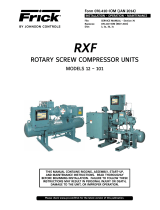
Figure 1 depicts the basic thermosyphon system when no
heat is being transferred from the oil to the refrigerant,
as is the case before a compressor starts. Liquid refriger-
ant, at condensing temperature, fills the tubes of the heat
exchanger and the rest of the thermosyphon loop to the
normal liquid level in the supply vessel. Because the den-
sity of the liquid refrigerant is the same in all parts of the
loop, there is no ow of refrigerant through the oil cooler.
Figure 1: Thermosyphon oil cooler - system not
operating
95°F
2.5 lb/ft³
95°F
36 lb/ft³
When the compressor package is operating, hot oil (above
the refrigerant temperature) ows through the refriger-
ant side of the oil cooler. Heat ows through the walls
from the higher temperature oil to the lower temperature
refrigerant causing the oil to become cooler. At the same

070.900-E (APR 20)
Page 4
THERMOSYPHON OIL COOLING
time, some of the refrigerant in the cooler tubes boils as it
absorbs its latent heat of vaporization from the oil.
The conguration of the oil cooler heat exchanger is such
that the refrigerant vapor created in the oil cooler can
easily escape and ow back to the supply vessel. The
liquid and vapor mixture that returns from the oil cooler is
separated in the supply vessel. The vapor is vented to the
inlet of the refrigerant condenser where it is reliquied.
Determine the rate of refrigerant vaporization in the oil
cooler by dividing the heat rejected from the oil by the
latent heat of vaporization for the specic refrigerant and
operating temperature. In order to ensure that all heat
transfer surfaces are wetted by the refrigerant, thermo-
syphon oil cooling systems are designed so that more
refrigerant ows through the oil cooler than is actually va-
porized. Assume the refrigerant design ow rate to be four
times the rate of vaporization. This is commonly referred
to as a 4:1 overfeed rate.
Note: When explaining the operation of a thermosyphon
system, it is necessary to distinguish between the
two vertical legs of the piping loop. In this paper,
the term vertical liquid supply line refers to the ver-
tical run of piping by which refrigerant is supplied
to the oil cooler, and the term wet return line refers
to the vertical run of piping by which refrigerant
returns to the supply vessel.
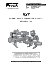
Figure 2 depicts the basic thermosyphon system in opera-
tion with a 4:1 overfeed rate. The refrigerant in the vertical
liquid supply line is all liquid, and its density is the same as
it was before the compressor package was operating. The
refrigerant in the wet return line is a mix of three parts
liquid and one part vapor (by mass). Because the density
of refrigerant vapor is much less than the density of the
liquid, the two-phase mixture in the wet return line has a
density that is considerably less than that of the refriger-
ant liquid in the vertical liquid supply line.
The difference in uid densities, when multiplied by the
height of the vertical legs in the thermosyphon piping
loop, yields a pressure differential.
Figure 2: Thermosyphon oil cooler - system operating
This pressure differential is the force that drives the ow
of refrigerant in the thermosyphon loop. Like any uid
owing in a piping system, the refrigerant in the thermo-
syphon loop experiences frictional forces which op-
pose the ow. The greater the refrigerant ow rate, the
greater the magnitude of the pressure losses due to these
frictional forces. The refrigerant ow rate stabilizes at a
point where the pressure drop due to friction losses in the
thermosyphon piping loop is exactly equal to the pressure
differential supplied by the difference in uid densities and
the height of the vertical legs in the piping loop.
When designing a thermosyphon oil cooling system, one
usually begins with the design oil cooler heat rejection and
an assumed refrigerant overfeed rate, say 4:1. The refrig-
erant piping is then designed so that total friction losses in
the piping loop at this ow rate are approximately half the
pressure differential provided by the differences in uid
density and the available liquid head. This approach adds
a margin of safety in the design to allow for errors in the
estimate of the available pressure and the pressure loss in
the piping and valving. A detailed calculation example is
given in Appendix A.
In an actual system, the available liquid head is xed and
the oil cooler heat rejection varies depending on the com-
pressor’s operating conditions. At lower rates of oil cooler
heat rejection, the refrigerant ow is less. It is a charac-
teristic of thermosyphon oil cooling systems that higher
oil temperatures result in more vaporization of refrigerant,
greater density differential, and higher refrigerant ow
rates. In other words, the more that oil cooling is needed,
the harder the thermosyphon system works to provide it.
Thermosyphon systems
There are numerous ways that a thermosyphon oil cooling
system can be piped. Below are some examples of com-
mon practice. However, this by no means covers all the
possible geometries that work. Alternate piping schemes
may be better suited for a particular application. It is the
responsibility of the system designer to determine the
best scheme to pursue for their system.
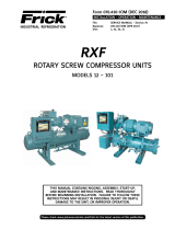
Flow-through thermosyphon receiver
In the arrangement shown in Figure 3, all of the high-
pressure liquid refrigerant leaving the condenser ows
through the thermosyphon receiver on its way to the
system receiver.
Liquid refrigerant, draining from the condenser, ows by
gravity to the thermosyphon receiver. Locate the connec-
tions on the thermosyphon receiver, which can be either
a horizontal or vertical pressure vessel, such that liquid
refrigerant lls this vessel up to a certain point and then
overows into the system receiver. Elevate the thermosy-
phon receiver relative to the system receiver, and connect
these two vessels using an equalizing line to ensure that
liquid refrigerant ows freely to the system receiver.
The liquid refrigerant supply to the oil cooler exits the
thermosyphon receiver well below the level of the over-
ow connection to the system receiver. This ensures an
uninterrupted 5 minute supply of refrigerant liquid to the
oil cooler regardless of system demands.

070.900-E (APR 20)
Page 5
THERMOSYPHON OIL COOLING
Figure 3: Flow-through thermosyphon receiver

070.900-E (APR 20)
Page 6
THERMOSYPHON OIL COOLING
When the compressor package is operating, hot oil (above
the refrigerant temperature) ows through the oil cooler.
As heat transfers from the higher temperature oil to the
lower temperature refrigerant, the oil is cooled while
some of the refrigerant in the oil cooler boils. During com-
pressor operation, the vertical liquid supply line supplying
refrigerant to the oil cooler contains liquid refrigerant,
while the wet return line exiting the oil cooler contains
a mixture of refrigerant liquid and vapor. Gravity causes
the denser refrigerant liquid to ow downward to the oil
cooler, displacing the less dense liquid and vapor mix-
ture and pushing it up the wet return line and back to the
thermosyphon receiver. The liquid and vapor mixture must
enter into the vapor space of the thermosyphon receiver
but at a level only slightly higher than the maximum liquid
level.
In the thermosyphon receiver, the vapor that returns from
the oil cooler is separated from the liquid and vented to
the inlet of the refrigerant condenser where it is once
again condensed.
The refrigerant in both the thermosyphon and system
receivers is saturated, and its temperature is equal to
the condensing temperature. Likewise, the refrigerant in
the oil cooler is saturated at the same temperature. This
refrigerant boils as it absorbs heat from the oil, but its
temperature does not change. This means the oil is cooled
to within an approach temperature of the refrigerant con-
densing temperature. Generally, this approach tempera-
ture is in the range of 15°F to 35°F (-9.4°C to 1.7°C). For
example, with a condensing temperature of 95°F (35°C),
the temperature of the oil exiting the cooler would be
approximately 110°F to 130°F (43.4°C to 54.4°C).

070.900-E (APR 20)
Page 7
THERMOSYPHON OIL COOLING
Figure 4: Elevated system receiver

070.900-E (APR 20)
Page 8
THERMOSYPHON OIL COOLING
Figure 5: Combination thermosyphon/system receiver

070.900-E (APR 20)
Page 9
THERMOSYPHON OIL COOLING
System receiver as thermosyphon receiver
When it is possible to install the system receiver at suf-
cient elevation (relative to the oil cooler), the system
high-pressure receiver can also serve as the refrigerant
supply vessel for thermosyphon oil cooling, as shown in
Figure 4.
Liquid refrigerant, draining from the condenser, ows by
gravity to the system receiver. Locate the outlet connec-
tions on this vessel such that the refrigerant liquid supply
to the oil coolers is physically lower than the liquid supply
to the system. This ensures an uninterrupted 5 minute
supply of refrigerant liquid to the oil cooler regardless of
system demands. To accomplish this, take refrigerant for
oil cooling off the bottom of the receiver and use a dip
tube for the main system liquid line. Project the nozzle on
the receiver for the thermosyphon liquid supply up into the
receiver to prevent dirt being drawn into the supply line
and eventually into the oil cooler.
If you cannot elevate the system receiver sufciently, an
alternative approach is shown in Figure 5. In this arrange-
ment, the system receiver is a vertical vessel. In the top
of the vessel is a weir dam over which all the liquid from
the condenser/s is forced to ow. The weir dam forms a
reservoir of liquid refrigerant to feed the thermosyphon
oil cooler. The excess liquid that spills over the weir into
the bottom of the receiver is used to feed the rest of the
system.
Take off the liquid feed to the thermosyphon oil cooler
from the receiver at the bottom of the weir dam. Size the
volume of the weir dam to provide at least 5 minutes of
liquid retention. The thermosyphon return line must enter
the receiver in the vapor space just above the liquid level
in the weir dam.
Multiple thermosyphon oil coolers
A large percentage of the refrigeration systems using
thermosyphon oil cooling involve multiple compressors
sharing a common thermosyphon supply vessel. A dis-
proportionate share of thermosyphon problems seem to
occur with these multiple-compressor systems. However,
the operating principles for a thermosyphon system with
multiple oil coolers are the same as those for a system
with a single oil cooler
Properly accounting for the total heat load on the oil cool-
ing system is the rst key to a successful design. Remem-
ber that at some operating conditions, compressor oil
cooler heat rejection is greatest at full load, while at other
operating conditions, heat rejection is greatest at part
load. Consider every compressor on the oil cooling system
and every conceivable state of compressor loading to nd
the worst case condition for total oil cooler heat rejec-
tion. If additional compressors are added to the system in
the future, common parts of the oil cooling system must
be sized to handle the heat rejection from these future
compressors.
It is possible to design a multiple-compressor system with
separate supply and return lines to each thermosyphon oil
cooler. In which case, this piping would be designed as for
a single-compressor system. Generally however, thermo-
syphon oil cooling systems serving multiple compressors
use common refrigerant liquid supply headers and liquid/
vapor return headers. See Figure 6 for the recommended
piping of a multiple compressor system using common
supply and return headers.
Caution
Consideration must be given to the order in which
compressors cycle on and off relative to the order
in which the oil coolers are fed refrigerant. When a
compressor cycles off, the thermosyphon oil cooler
for that compressor lls with liquid refrigerant.
This can temporarily starve other oil coolers further
downstream resulting in nuisance compressor shut
downs on high oil temperature.
If in the designer’s judgement, compressor order cycle could
be an issue for a particular system, then separate liquid feed
lines can be run as needed to avoid nuisance compressor shut
downs. Alternatively, the compressors that run the most can
be located at the beginning of the supply header.
A thermosyphon system serving multiple compressors is
very likely to have a liquid supply header that runs hori-
zontally through the engine room. Vapor bubbles form in
this header as the saturated liquid refrigerant it contains
absorbs heat from the warm engine room and vaporizes.
Make sure to vent these bubbles back to the supply vessel
before they can combine to form a large vapor bubble
that would interfere with the free ow of liquid refriger-
ant to the oil coolers. The easiest way to accomplish this
is to pitch the liquid header so it rises 1/4 in. per ft in the
direction of ow, moving away from the supply vessel. If
the “tail end” of the liquid header is then connected to the
return header, any vaporized refrigerant can easily return
to the supply vessel. Ensure the vertical liquid supply line
carrying liquid refrigerant to the individual oil coolers exits
the bottom of the supply header. The end of the supply
header cannot exceed the elevation of the supply vessel.
It is also necessary to pitch the horizontal return header
carrying the two-phase refrigerant mixture back to the
supply vessel. Pitch the header so it falls 1/4 in. per ft or
more in the direction of ow, moving towards the sup-
ply vessel. Ensure the wet return line carrying refrigerant
liquid and vapor from the individual oil coolers enters the
top of the return header.
A variant of this system is the situation shown in Detail A
of Figure 6. In some applications, it is impossible to get all
the return header above the supply vessel. In this case, the
return header can be split in two sections with a vertical
wet return line in the middle. However, in this situation,
you must slope the return header in the engine room up-
ward 1/4 in. per ft or more in the direction of ow toward
the vertical wet return line. This allows vapor bubbles in
the wet return line in the engine room to return to the
supply vessel. Slope the part of the return header that is
above the supply vessel down toward the supply vessel as
before.

070.900-E (APR 20)
Page 10
THERMOSYPHON OIL COOLING
Figure 6: Multiple thermosyphon oil coolers
DETAIL A

070.900-E (APR 20)
Page 11
THERMOSYPHON OIL COOLING
Typical thermosyphon oil cooler
piping details
The previous diagrams have purposely left out valves
required for proper operation in order to show the pip-
ing more clearly. Figure 7 shows the minimum number of
valves needed to operate the system.
Service isolation valves are sometimes used in the refrig-
erant supply and return lines to the oil cooler, and are rec-
ommended for installations where multiple thermosyphon
coolers are connected to a common supply vessel. Gener-
ously size these valves and ensure they are a low pressure
drop design. Do not use globe valves. Additionally, install a
sight glass in the vertical leg of the refrigerant supply and
return lines of every oil cooler to facilitate trouble shoot-
ing the system if necessary.
Provide oil drain valves at the low points to the supply
vessel and the refrigerant side of the thermosyphon oil
coolers. Over time, oil accumulates in these locations and
interferes with the efcient operation of the thermosyphon
system. Periodic removal of oil is required.
Pressure vessel codes generally require the installation of
a pressure safety valve on the oil side of the thermosy-
phon oil cooler. This pressure safety valve may discharge
to the compressor package’s oil separator vessel.
Oil temperature control
The temperature of the oil leaving the thermosyphon oil
cooler is generally about 15°F to 35°F (-9.4°C to 1.7°C)
above the condensing temperature. For installations where
the condensing temperature or the engine room tempera-
ture is not expected to drop below about 65°F (18.3°C),
oil temperature control is not generally required. Without
control, the oil temperature simply oats with the con-
densing temperature. If a thermosyphon oil cooling system
without temperature control is being considered for non-
FRICK compressors, contact the compressor manufacturer
to advise the minimum allowable temperature for oil
supplied to the compressor. For FRICK compressors, the
minimum oil temperature at start-up is 50°F (10°C).
Older discussions of thermosyphon oil cooling sometimes
mention controlling the supply of liquid refrigerant to the
oil cooler as a method of oil temperature control. This
method is rarely seen in the eld today and is not recom-
mended. By far the most common method is direct control
of the oil temperature with a cooler bypass oil mixing
valve.
Control of oil temperature with a bypass mixing valve on
the oil side affords inexpensive, automatic control. At
higher condensing temperatures (95°F [35°C]), the bypass
remains closed and the oil temperature oats with the
condensing temperature. At low condensing temperatures,
some hot oil is bypassed around the cooler and mixed with
cooled oil to maintain a constant oil supply temperature of
approximately 130°F (54.4°C) to the compressor.
Figure 7: Thermosyphon oil cooler piping
6 ft

070.900-E (APR 20)
Page 12
THERMOSYPHON OIL COOLING
System dynamics
All previous discussions of thermosyphon oil cooler opera-
tion have assumed steady state operation. Real world
refrigeration systems seldom operate at steady state
conditions, but rather experience many dynamics including
startup, shutdown, load changes, hot gas defrosting of air
units, ice maker harvesting, condenser capacity changes,
and other conditions.
The system dynamics most likely to affect the operation
of thermosyphon oil cooling systems are those that cause
intermittent interruptions in system refrigerant ows or
changes in system condensing pressure (recall that the
thermosyphon oil cooling system operates at the system
condensing pressure). An adequate supply of refriger-
ant liquid in the thermosyphon receiver permits a system
to sustain operation during brief interruptions in system
refrigerant ow.
Rapid decreases in system condensing pressure can lead
to blowout of the refrigerant in the oil cooler circuit. Oil
cooler refrigerant circuit blowout normally occurs when
there is a large need for system hot gas, for example,
defrosting of air units or harvesting ice makers. It can also
be caused by a large, step increase in condenser capacity,
for example, a condenser fan or pump cycling on. In either
case, it is the sudden decrease in system condensing
pressure that causes this to occur.
In normal, steady state operation, the refrigerant in the
thermosyphon oil cooling circuit is saturated and its tem-
perature is equal to the saturation temperature at the sys-
tem condensing pressure. When the condensing pressure
suddenly drops, the refrigerant in the thermosyphon oil
cooling circuit is at a temperature higher than the equiva-
lent boiling pressure. This causes a portion of the liquid
refrigerant in the thermosyphon loop to ash to a vapor.
The refrigerant expands dramatically as it evaporates and
the rapidly expanding vapor can push the remaining liquid
refrigerant out of the oil cooler, the vertical liquid supply
line, and the wet return line.
Following this evacuation of liquid refrigerant from the
heat exchanger, the liquid returns due to gravity and
normal thermosyphon operation resumes. Until the liquid
refrigerant returns to the oil cooler however, no oil cooling
occurs. It is quite possible for oil temperatures to become
high enough to cause a safety shutdown of a compressor
package before the oil cooling system can recover from a
blowout.
Note: During an oil cooler circuit blowout, liquid refriger-
ant can be propelled at high velocity by the expand-
ing vapor. This can impose severe hydraulic shocks
on the piping system.
Maintaining stable condensing pressures minimizes the
occurrence of oil cooler circuit blowout. This may require
defrosting fewer air units at a time, employing more so-
phisticated condenser capacity controls, or other mea-
sures. Finally, increasing the elevation of the thermosy-
phon receiver and oversizing the vertical liquid supply line
supplying liquid to the oil coolers tends to suppress ash
boiling in the oil cooler following a condensing pressure
decrease and lead to a more rapid recovery.

070.900-E (APR 20)
Page 13
THERMOSYPHON OIL COOLING
System sizing
The sizing tables and graphs are all based on 95°F (35°C)
condensing and a 4:1 recirculation ratio for R-717. For
higher condensing temperatures, it is recommended to
increase all sizing to ensure that proper refrigerant ow
is maintained. Proper operation of thermosyphon systems
depends upon refrigerant ow entirely by gravity head.
Unaccounted for pressure drop in refrigerant lines and
valves can prevent refrigerant ow. If any line sizing is
questionable, increase to the next larger size and increase
the static head of liquid supply to the oil cooler. A more
precise pressure loss calculation is presented in Appendix
A and can help resolve questionable line sizes.
The rst step in sizing a system is to determine the total
oil cooling heat load from the compressor oil cooling heat
of rejection (OCHR) tables. For this example, assume an oil
cooler heat load of 653,000 Btu/h on an ammonia system
condensing at 95°F (35°C).
Step 1: Sizing the Thermosyphon Receiver (See Table 1).
Under the appropriate refrigerant, proceed down the col-
umn to the required heat load and select the vessel with a
capacity rating that equals or exceeds the load.
12 in. x 6 ft 500,000 Btu/h
653,000 Btu/h - - - - - Example Heat Load
16 in. x 6 ft 875,000 Btu/h - - - - - Select
Step 2: Sizing the Liquid Feed Line to the Oil Cooler and
the Return Line to the Thermosyphon Receiver. See Fig-
ures 8, 9, and 10 for R-717.
A) Liquid Feed Line to Oil Cooler
See Figure 8 for R-717 heat loads to 1000 kBtu/h. Follow
along the horizontal axis to the required heat load and
read up to the nearest line curve, not to exceed:
0.10 psid/100 ft, R-717 (Figures 8, 9, and 10)
Example: 653,000 Btu/h
2 in. - above 0.10 psid/100 ft - - - - - Too Small
2 1/2 in. - 0.058 psid/100 ft - - - - - Select
3 in. - 0.019 psid/100 ft - - - Larger Than Required
B) Return Line from oil cooler
Return to Figure 8. Follow the same procedure as Step 2A
but do not exceed:
0.04 psid/100 ft, R-717 (Figures 8, 9, and 10)
Example: 653,000 Btu/h
2 1/2 in. - 0.058 psid/100 ft - - - - - - Too Small
3 in. - 0.019 psid/100 ft - - - - - - - - - Select
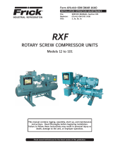
Step 3: Sizing the Return Vent Line from the Thermosy-
phon Receiver to the Condenser. See Figure 11.
Calculate the mass ow rate (lb/min) as follows:
A. Convert the oil cooler heat load in Btu/h to Btu/
min
B. Divide the Btu/min load by the enthalpy dif-
ference of the refrigerant phase change at the
system condensing temperature.
H = 483.2 Btu/lb (R-717 at 95°F)
H = 488.5 Btu/lb (R-717 at 90°F)
See Figure 11. Follow along the vertical axis to the
calculated mass ow rate, read across to the slanted
reference line and down to the return vent line size.
Example: 653,000 Btu/h
Select 2 1/2 in. or 3 in. to minimize pressure drop and
assure system ow.
Btu/min lb min
Btu/min
Table 1: Thermosyphon receiver sizing*
Shell Size R-717 OCHR
(Btu/h)
maximum
8 in. x 6 ft (vertical) 210,000
12 in. x 6 ft (vertical) 500,000
16 in. x 6 ft (vertical) 875,000
20 in. x 6 ft (horizontal or vertical) 1,400,000
24 in. x 5 ft (horizontal or vertical) 2,000,000
30 in. x 5 ft (horizontal or vertical) 2,600,000
*Based on 5 min liquid supply, 95°F (35°C) condensing.
Btu/min
Btu/min
Btu/lb lb/min
Btu/hr

070.900-E (APR 20)
Page 14
THERMOSYPHON OIL COOLING
Figure 8: R-717 TSOC pipe sizing, 0 kBtu/h to 1000 kBtu/h - OCHR
IN. IN.
IN.
IN.
IN.

070.900-E (APR 20)
Page 15
THERMOSYPHON OIL COOLING
Figure 9: R-717 TSOC pipe sizing, 1000 kBtu/h to 3000 kBtu/h - OCHR
IN.
IN.
IN.

070.900-E (APR 20)
Page 16
THERMOSYPHON OIL COOLING
Figure 10: R-717 TSOC pipe sizing, 3000 kBtu/h to 5000 kBtu/h - OCHR
IN.
IN.
IN.

070.900-E (APR 20)
Page 17
THERMOSYPHON OIL COOLING
Figure 11: R-717 return vent line sizing
.

070.900-E (APR 20)
Page 18
THERMOSYPHON OIL COOLING
Appendix A - Required minimum liquid head
height calculation
The sizing example given previously provides reasonably
sized piping. However, if the graphs yield a size that seems
questionable, a more rigorous calculation can be made as
outlined below. In fact, after sizes have been selected from
the graphs, it is still benecial to calculate pressure losses
in the piping and the minimum head height.
The basic calculation process is to rst determine the
initial pipe sizes from the sizing graphs.
1. For a given oil heat rejection rate, determine the re-
frigerant ow rate through the piping.
2. After the ow rate is known, determine the pressure
loss in the liquid supply line using the Moody diagram.
3. Determine the pressure loss in the return line, which
is a mixture of gas and liquid, from the charts in this
appendix.
4. Then, add the pressure losses in the thermosyphon
supply and return lines, plus an estimate of the cooler
pressure loss to get the total loss in the piping. Com-
pare this number to the available liquid head to ensure
that the selected piping is adequate.
For this example, assume that the thermosyphon oil cool-
ing load is 425 MBH for an ammonia system at 95°F (35°C)
condensing. From Figure 8, a 2 in. liquid supply line to
the oil cooler results in a pressure loss of 0.08 psi/100 ft.
Because this is below the limit of 0.10 psi/100 ft, the 2 in.
pipe is acceptable. However, for the return line, the 0.08
psi/100 ft exceeds the limit of 0.04 psi/100 ft. A 2 1/2 in.
pipe must be used for the return line from the thermosy-
phon oil cooler.
The next step is to determine the actual ow rate at an
assumed 4:1 recirculation ratio from equation 1.
Note: Figures 8 to 10 are based on a 4:1 recirculation
ratio.
By denition, the refrigerant ow rate is four times the
evaporation rate which you can determine from the oil
cooler heat rejection and the latent heat of vaporization.
Determine the latent heat of vaporization or hfg from the
FRICK Engineering Data and Tables pamphlet (E20-4G/J66)
at 95°F (35°C) condensing temperature.
4 x 425,000 Btu/h
483.2 Btu/lb x 60 min/h
Refrigerant Flow Rate = 58.6 lb/min
With the ow rate known, calculate the pressure loss in
the liquid supply line using the Moody diagram and the
Darcy-Weisbach formula (see an undergraduate engineer-
ing text on uid mechanics). In order to use the Moody
diagram, perform the following steps:
1. Determine the velocity of the refrigerant in the liquid
line. The velocity in the 2 in. liquid supply pipe is de-
ned by equation 2.
2. Obtain the density of the liquid refrigerant and cross
sectional area of a 2 in. schedule 40 pipe from the
FRICK Engineering Data and Tables pamphlet (E20-4G/
J66) at 95°F (35°C) condensing temperature.
58.6 lb/min x 144 in./ft
36.67 lb/ft x 3.36 in. 68.5 ft/min = 4110 ft/h
3. Calculate the Reynolds number using equation 3. Ob-
tain the viscosity of liquid ammonia at 95°F (35°C) from
CoolWare™ software. The Reynolds number does not
have units.
36.67 lb/ft x 4110 ft/h x 0.1723 ft
0.2985 lb/ft - h
4. Determine the relative roughness of the pipe given
by equation 4. You can nd the absolute roughness
for various materials along with a Moody diagram in
Mark’s Standard Handbook for Mechanical Engineers.
ft
ft
Given the Reynolds number and relative roughness, the
Moody diagram indicates the friction factor is 0.023.
Calculate the pressure drop in the pipe from the friction
factor using equation 5. (assume 100 ft of pipe). The result
is that 100 ft of 2 in. schedule 40 pipe has a pressure loss
of 0.067 psi with 58.6 lb/min of liquid ammonia owing
through it at 95°F (35°C).
There are typically elbows and at least one valve in the
liquid supply line. The pressure drop through the ttings
and valves can be handled by using equivalent lengths; re-
fer to Section V in the FRICK Engineering Data and Tables
pamphlet (E20-4G/J66). A table of equivalent lengths for
valves and ttings is given.
32.2 ft-lb/lbf - s
100 ft of 2 in. pipe
1 ft1 h
144 in.
3600 s
0.023 x 36.67 lb/ft 100 ft
0.1723 ft
(4110 ft/h)
For our example, assume that there are two 2 in. long
radius elbows and one 2 in. angle valve. Reading the table
for ferrous ttings results in an equivalent length of 2.3
ft for a welded elbow and 25 ft for a anged angle valve.
Equation 6 provides the total equivalent length of straight
pipe:

070.900-E (APR 20)
Page 19
THERMOSYPHON OIL COOLING
Equation 7 provides the total pressure loss in the thermo-
syphon liquid supply line:
The next step is to nd the refrigerant side pressure drop
through the thermosyphon oil cooler. Find this on a heat
exchanger rating sheet.
It is now necessary to determine the pressure drop
through the thermosyphon return line.
Note: Figures 8 to 10 are based on a 4:1 recirculation ratio
and the assumption that all the refrigerant ow-
ing through the pipe is liquid. The pressure losses
shown on the vertical axis of the graphs are correct
only for the thermosyphon liquid supply line. The
return line has a mixture of gas and liquid for which
the assumption of all liquid ow in the pipe is not
valid.
The calculation of gas and liquid mixture, or what is
referred to as two phase ow pressure losses by hand,
is very time-consuming and involved. To make the siz-
ing easier, the traditional approach is to select the pipe
based on the ow assumed to be all liquid, but use a very
low pressure loss per length of pipe limit. This in effect
increases the pipe size which compensates for the higher
pressure loss when the ow is a mixture of gas and liquid.
The 0.04 psi/100 ft limit selected is based on experience
gained from actual installations.
For example, when selecting thermosyphon return lines
for ammonia systems using a 0.04 psi/100 ft limit, the
actual pressure drop in the pipe, although unknown, is not
so high that it affects the performance of the system in
the eld.
Note: We have condensed a large amount of data into
Figure 12. These graphs provide an easy method to
determine the two phase ow pressure drop in the
return line. They are valid for recirculation ratios
from 2:1 up to 5:1 and for 85°F to 105°F
(29.4°C to 40.6°C) condensing temperatures.
Returning to our example, the refrigerant ow rate is 58.6
lb/min in a 2 1/2 in. pipe. From Figure 12, the two phase
ow pressure drop is roughly 1.5 psig/100 ft of pipe. The
liquid line is expected to have elbows and at least one
valve. There is little engineering data available for two
phase ow pressure losses through ttings and valves. In
lieu of better data, determine an equivalent length, as for
the liquid line loss, but multiply this by the two phase ow
pressure loss.
Assume that the return line has two long radius elbows
and one angle valve. From Section V in the FRICK En-
gineering Data and Tables pamphlet (E20-4G/J66), the
equivalent length of the elbows is 2.7 ft and the valve is
28 ft. Equation 9 provides the total equivalent length of
pipe for the thermosyphon return line, where "h" is the
required minimum liquid head height that is solved for.
Then, multiply this equivalent length by the pressure loss
for straight pipe. The total pressure loss is calculated by
equation 9.
Determine the total pressure loss in the piping by adding
the total pressure loss in the liquid line, the pressure drop
through the oil cooler, and the total pressure loss in the
return line. Equation 10 provides the total loss.
Note: The pressure loss through the exchanger in this
example is 1 psig.
Total System Pressure Loss = 0.0025 psi + 1.00 psi + 0.59 psi (10)
Total System Pressure Loss = 1.62 psi
The total piping pressure drop of 0.87 psig must be over-
come by the available liquid head. To calculate the ther-
mosyphon driving pressure, determine the density of the
refrigerant in the return line. Calculate this using equation
11. The total ow of refrigerant is divided into 75% liquid
and 25% gas for a 4:1 recirculation ratio.
lb/min
lb/min
lb/min
lb/ft
lb/ftlb/ft
Equation 12 provides the driving pressure due to the dif-
ference in densities of the liquid in the supply and return
pipe.
Driving Pressure = 1.90 psi
lb/ft
144 in./ft x 32.2 ft-lb/lbf - s
lb/ft ft/sft
In this case, the height of the thermosyphon receiver
above the oil cooler is 8 ft. The driving pressure to push
the refrigerant through the piping and oil cooler is 1.90 psi.
The frictional losses are lower at 1.62 psi. In a real system,
with these pipe sizes, the ow rate would increase until
the frictional pressure loss matched the driving pressure.
This means the recirculation ratio is somewhat higher than
initially assumed. This design is acceptable.
The calculation presented has been simplied for ease of
presentation. A real system likely has more complicated
piping with many more ttings, valves, and other compo-
nents to consider. However, the techniques presented here
extend to any system. As mentioned in the beginning of
this paper, ensure only qualied individuals familiar with
industrial refrigeration piping practice who can determine
the adequacy of the techniques presented design these
systems.
(7) (9)

070.900-E (APR 20)
Page 20
THERMOSYPHON OIL COOLING
Figure 12: R-717 two-phase pressure drop
/