Page is loading ...

MultiMaster 160
Mig / Tig / Stick Welding Package
F15-678-D 07 / 2005
Instruction Manual

2
BE SURE THIS INFORMATION REACHES THE OPERATOR
These INSTRUCTIONS are for experienced operators. If you are not fully familiar with
the principles of operation and safe practices for arc welding and cutting equipment,
we urge you to read our booklet, "Precautions and Safe Practices for Arc Welding,
Cutting, and Gouging," Form 52-529. Do NOT permit untrained persons to install,
operate, or maintain this equipment. Do NOT attempt to install or operate this
equipment until you have read and fully understand these instructions. If you do not
fully understand these instructions, contact your supplier for further information. Be
sure to read the Safety Precautions before installing or operating this equipment.
Copies of this manual can be obtained by any of the following;
Contacting your local ESAB supplier.
Downloading a copy from the ESAB web site at
www.esabna.com
Sending a written request to
ESAB WELDING & CUTTING PRODUCTS
ATTN: LITERATURE DEPT.
411 S EBENEZER ROAD
FLORENCE SC 29501
USER RESPONSIBILITY
This equipment will perform in conformity with the description thereof contained in this manual and
accompanying labels and/or inserts when installed, operated, maintained and repaired in accordance
with the instructions provided. This equipment must be checked periodically. Malfunctioning or
poorly maintained equipment should not be used. Parts that are broken, missing, worn, distorted
or contaminated should be replaced immediately. Should such repair or replacement become
necessary, the manufacturer recommends that a telephone or written request for service advice
be made to the Authorized Distributor from whom it was purchased.
This equipment or any of its parts should not be altered without the prior written approval of the
manufacturer. The user of this equipment shall have the sole responsibility for any malfunction
which results from improper use, faulty maintenance, damage, improper repair or alteration by
anyone other than the manufacturer or a service facility designated by the manufacturer.

3
SECTION NO. PAGE NO.
SECTION 1.0 - SAFETY PRECAUTIONS.........................................................................................................................................3
SECTION 2.0 - INTRODUCTION .......................................................................................................................................................9
SECTION 3.0 - INSTALLATION ......................................................................................................................................................13
3.1 LOCATION..........................................................................................................................................................13
3.2 ELECTRICAL INPUT CONNECTIONS .............................................................................................................13
3.2.1 INPUT ELECTRICAL REQUIREMENTS...........................................................................................................13
3.2.2 INPUT PLUG ......................................................................................................................................................13
3.3 SECONDARY OUTPUT CONNECTIONS.........................................................................................................13
3.4 WIRE FEEDER MECHANISM ...........................................................................................................................13
3.4.1 DRIVE ROLLS ....................................................................................................................................................13
3.4.2 WELD WIRE SPOOL INSTALLATION ..............................................................................................................13
3.4.3 THREADING THE WELDING WIRE .................................................................................................................14
3.4.4 SPOOL BRAKE DRAG ADJUSTMENT.............................................................................................................14
3.5 CONNECTION OF SHIELDING GAS SUPPLY ................................................................................................14
3.5.1 R-33-FM-580 REGULATOR (OPTIONAL) ........................................................................................................14
3.5.2 TO REGULATE FLOW.......................................................................................................................................15
SECTION 4.0 - OPERATION ............................................................................................................................................................ 16
4.1 STANDARD CONTROLS...................................................................................................................................16
4.1.1 POWER ON/OFF SWITCH ................................................................................................................................16
4.2.2 TEMP LAMP .......................................................................................................................................................16
4.1.3 PROCESS SELECTOR SWITCH ......................................................................................................................16
4.1.4 SECONDARY WELDING CONNECTIONS.......................................................................................................16
4.1.5 WIRE FEED SPEED CONTROL .......................................................................................................................16
4.1.5 VOLTAGE CONTROL ........................................................................................................................................16
4.1.7 CURRENT CONTROL .......................................................................................................................................16
4.1.8 HOT START .......................................................................................................................................................16
4.2 OPERATING PROCEDURES............................................................................................................................18
4.2.1 MIG WELDING SET-UP.....................................................................................................................................18
4.2.2 TIG WELDING SET-UP .....................................................................................................................................19
4.2.3 STICK WELDING SET-UP.................................................................................................................................20
SECTION 5.0 - MAINTENANCE ......................................................................................................................................................21
5.1 MAINTENANCE AND SERVICE .......................................................................................................................21
5.2 INSPECTION AND SERVICE............................................................................................................................21
5.2.1 POWER SOURCE..............................................................................................................................................21
5.2.1.1 RECTIFIERS AND TRANSISTORS ..................................................................................................................21
5.2.1.2 FAN MOTOR ......................................................................................................................................................21
5.2.1.3 TRANSFORMER ................................................................................................................................................21
5.2.1.4 OVER-TEMPERATURE PROTECTION ............................................................................................................21
5.2.2 WIRE FEEDER...................................................................................................................................................21
SECTION 6.0 - REPLACEMENT PARTS
........................................................................................................................................23
6.1 REPLACEMENT PARTS ...................................................................................................................................23
6.2 GENERAL ...........................................................................................................................................................23
6.3 ORDERING.........................................................................................................................................................23
Table of Contents

4
Table of Contents

5
WARNING: These Safety Precautions are for
your protection. They summarize precaution-
ary information from the references listed in
Additional Safety Information section. Before
performing any installation or operating procedures, be
sure to read and follow the safety precautions listed below
as well as all other manuals, material safety data sheets,
labels, etc. Failure to observe Safety Precautions can result
in injury or death.
PROTECT YOURSELF AND OTHERS --
Some welding, cutting, and gouging
processes are noisy and require ear
protection. The arc, like the sun, emits
ultraviolet (UV) and other radiation and
can injure skin and eyes. Hot metal can cause burns.
Training in the proper use of the processes and equip-
ment is essential to prevent accidents. Therefore:
1. Always wear safety glasses with side shields in any work
area, even if welding helmets, face shields, and goggles
are also required.
2. Use a face shield fitted with the correct filter and cover
plates to protect your eyes, face, neck, and ears from
sparks and rays of the arc when operating or observing
operations. Warn bystanders not to watch the arc and
not to expose themselves to the rays of the electric-arc
or hot metal.
3. Wear flameproof gauntlet type gloves, heavy long-sleeve
shirt, cuffless trousers, high-topped shoes, and a weld-
ing helmet or cap for hair protection, to protect against
arc rays and hot sparks or hot metal. A flameproof apron
may also be desirable as protection against radiated
heat and sparks.
4. Hot sparks or metal can lodge in rolled up sleeves,
trouser cuffs, or pockets. Sleeves and collars should be
kept buttoned, and open pockets eliminated from the
front of clothing
5. Protect other personnel from arc rays and hot sparks
with a suitable non-flammable partition or curtains.
6. Use goggles over safety glasses when chipping slag or
grinding. Chipped slag may be hot and can fly far.
Bystanders should also wear goggles over safety glasses.
FIRES AND EXPLOSIONS -- Heat from
flames and arcs can start fires. Hot slag
or sparks can also cause fires and ex-
plosions. Therefore:
1. Remove all combustible materials well away from the
work area or cover the materials with a protective non-
flammable covering. Combustible materials include wood,
cloth, sawdust, liquid and gas fuels, solvents, paints and
coatings, paper, etc.
2. Hot sparks or hot metal can fall through cracks or
crevices in floors or wall openings and cause a hidden
smoldering fire or fires on the floor below. Make certain
that such openings are protected from hot sparks and
metal.
3. Do not weld, cut or perform other hot work until the
workpiece has been completely cleaned so that there
are no substances on the workpiece which might pro-
duce flammable or toxic vapors. Do not do hot work on
closed containers. They may explode.
4. Have fire extinguishing equipment handy for instant use,
such as a garden hose, water pail, sand bucket, or
portable fire extinguisher. Be sure you are trained in its
use.
SAFETY PRECAUTIONS
5. Do not use equipment beyond its ratings. For example,
overloaded welding cable can overheat and create a fire
hazard.
6. After completing operations, inspect the work area to
make certain there are no hot sparks or hot metal which
could cause a later fire. Use fire watchers when neces-
sary.
7. For additional information, refer to NFPA Standard 51B,
"Fire Prevention in Use of Cutting and Welding Pro-
cesses", available from the National Fire Protection Asso-
ciation, Batterymarch Park, Quincy, MA 02269.
ELECTRICAL SHOCK -- Contact with live
electrical parts and ground can cause
severe injury or death. DO NOT use AC
welding current in damp areas, if move-
ment is confined, or if there is danger of
falling.
1. Be sure the power source frame (chassis) is connected
to the ground system of the input power.
2. Connect the workpiece to a good electrical ground.
3. Connect the work cable to the workpiece. A poor or
missing connection can expose you or others to a fatal
shock.
4. Use well-maintained equipment. Replace worn or dam-
aged cables.
5. Keep everything dry, including clothing, work area, cables,
torch/electrode holder, and power source.
6. Make sure that all parts of your body are insulated from
work
and from ground.
7. Do not stand directly on metal or the earth while working
in tight quarters or a damp area; stand on dry boards or
an insulating platform and wear rubber-soled shoes.
8. Put on dry, hole-free gloves before turning on the power.
9. Turn off the power before removing your gloves.
10. Refer to ANSI/ASC Standard Z49.1 (listed on next page)
for specific grounding recommendations. Do not mis-
take the work lead for a ground cable.
ELECTRIC AND MAGNETIC FIELDS —
May be dangerous. Electric current flow-
ing through any conductor causes lo-
calized Electric and Magnetic Fields
(EMF). Welding and cutting current cre-
ates EMF around welding cables and
welding machines. Therefore:
1. Welders having pacemakers should consult their physi-
cian before welding. EMF may interfere with some pace-
makers.
2. Exposure to EMF may have other health effects which are
unknown.
3. Welders should use the following procedures to minimize
exposure to EMF:
A. Route the electrode and work cables together. Secure
them with tape when possible.
B. Never coil the torch or work cable around your body.
C. Do not place your body between the torch and work
cables. Route cables on the same side of your body.
D. Connect the work cable to the workpiece as close as
possible to the area being welded.
E. Keep welding power source and cables as far away
from your body as possible.

6
FUMES AND GASES -- Fumes and
gases, can cause discomfort or harm,
particularly in confined spaces. Do
not breathe fumes and gases. Shield-
ing gases can cause asphyxiation.
Therefore:
1. Always provide adequate ventilation in the work area by
natural or mechanical means. Do not weld, cut, or gouge
on materials such as galvanized steel, stainless steel,
copper, zinc, lead, beryllium, or cadmium unless posi-
tive mechanical ventilation is provided. Do not breathe
fumes from these materials.
2. Do not operate near degreasing and spraying opera-
tions. The heat or arc rays can react with chlorinated
hydrocarbon vapors to form phosgene, a highly toxic
gas, and other irritant gases.
3. If you develop momentary eye, nose, or throat irritation
while operating, this is an indication that ventilation is not
adequate. Stop work and take necessary steps to im-
prove ventilation in the work area. Do not continue to
operate if physical discomfort persists.
4. Refer to ANSI/ASC Standard Z49.1 (see listing below)
for specific ventilation recommendations.
5. WARNING: This product, when used for welding or
cutting, produces fumes or gases which
contain chemicals known to the State of
California to cause birth defects and, in
some cases, cancer. (California Health &
Safety Code
§25249.5 et seq.)
CYLINDER HANDLING -- Cylinders, if
mishandled, can rupture and violently
release gas. Sudden rupture of cylin-
der, valve, or relief device can injure or
kill. Therefore:
1. Use the proper gas for the process and use the proper
pressure reducing regulator designed to operate from
the compressed gas cylinder. Do not use adaptors.
Maintain hoses and fittings in good condition. Follow
manufacturer's operating instructions for mounting regu-
lator to a compressed gas cylinder.
2. Always secure cylinders in an upright position by chain
or strap to suitable hand trucks, undercarriages, benches,
walls, post, or racks. Never secure cylinders to work
tables or fixtures where they may become part of an
electrical circuit.
3. When not in use, keep cylinder valves closed. Have
valve protection cap in place if regulator is not con-
nected. Secure and move cylinders by using suitable
hand trucks. Avoid rough handling of cylinders.
4. Locate cylinders away from heat, sparks, and flames.
Never strike an arc on a cylinder.
5. For additional information, refer to CGA Standard P-1,
"Precautions for Safe Handling of Compressed Gases in
Cylinders", which is available from Compressed Gas
Association, 1235 Jefferson Davis Highway, Arlington,
VA 22202.
EQUIPMENT MAINTENANCE -- Faulty or
improperly maintained equipment can
cause injury or death. Therefore:
1. Always have qualified personnel perform the installa-
tion, troubleshooting, and maintenance work. Do not
perform any electrical work unless you are qualified to
perform such work.
2. Before performing any maintenance work inside a power
source, disconnect the power source from the incoming
electrical power.
3. Maintain cables, grounding wire, connections, power
cord, and power supply in safe working order. Do not
operate any equipment in faulty condition.
4. Do not abuse any equipment or accessories. Keep
equipment away from heat sources such as furnaces,
wet conditions such as water puddles, oil or grease,
corrosive atmospheres and inclement weather.
5. Keep all safety devices and cabinet covers in position
and in good repair.
6. Use equipment only for its intended purpose. Do not
modify it in any manner.
ADDITIONAL SAFETY INFORMATION -- For
more information on safe practices for elec-
tric arc welding and cutting equipment, ask
your supplier for a copy of "Precautions and
Safe Practices for Arc Welding, Cutting and
Gouging", Form 52-529.
The following publications, which are available from the
American Welding Society, 550 N.W. LeJuene Road, Mi-
ami, FL 33126, are recommended to you:
1. ANSI/ASC Z49.1 - "Safety in Welding and Cutting"
2. AWS C5.1 - "Recommended Practices for Plasma Arc
Welding"
3. AWS C5.2 - "Recommended Practices for Plasma Arc
Cutting"
4. AWS C5.3 - "Recommended Practices for Air Carbon
Arc Gouging and Cutting"
5. AWS C5.5 - "Recommended Practices for Gas Tung-
sten Arc Welding“
6. AWS C5.6 - "Recommended Practices for Gas Metal Arc
Welding"“
7. AWS SP - "Safe Practices" - Reprint, Welding Hand-
book.
8. ANSI/AWS F4.1, "Recommended Safe Practices for
Welding and Cutting of Containers That Have Held
Hazardous Substances."
MEANING OF SYMBOLS - As used through-
out this manual: Means Attention! Be Alert!
Your safety is involved.
Means immediate hazards which, if
not avoided, will result in immediate,
serious personal injury or loss of life.
Means potential hazards which could
result in personal injury or loss of life.
Means hazards which could result in
minor personal injury.

9
SECTION 2 INTRODUCTION
Input
Primary Input Voltage ....................................................................... 208 Vac, 1-Phase
......................................................................................................... 230 Vac, 1-Phase
Primary Input Current .......................................................................30 Amp @ 208 Vac
......................................................................................................... 27 Amp @ 230 Vac
Frequency ........................................................................................ 50/60Hz
Power Factor .................................................................................... 0.81
Nominal Power - MIG ....................................................................... 5.4KVA
Nominal Power - electrode ............................................................... 6.3KVA
Nominal Power - TIG........................................................................3.9KVA
Protective Fuses............................................................................... 20A time-lag
Degree of Protection ........................................................................ IP 21
Insulation Class ................................................................................ F
Operating Temperature .................................................................... From 14°F to 104°F (-10°C to +40°C)
Output
Duty Cycle - MIG .............................................................................. 160A - 60%
Duty Cycle - electrode ...................................................................... 160A - 60%
Duty Cycle - TIG DC......................................................................... 160A - 70%
OCV.................................................................................................. 75V
Arc Voltage - MIG .............................................................................13.0 - 23.0
Arc Voltage - electrode .....................................................................20.2 - 26.4
Arc Voltage - TIG .............................................................................. 10.2 - 16.4
Regulation range - MIG .................................................................... 20 - 160
Regulation range - electrode ............................................................ 5 - 160A
Regulation range - TIG..................................................................... 10 - 160A
Hot Start ........................................................................................... Adjustable
Arc Force.......................................................................................... Automatic (built-in)
Antisticking ....................................................................................... Automatic (built-in)
Ignition - electrode............................................................................ Scratch
Ignition - TIG.....................................................................................Lift-arc
Wire Spool ........................................................................................ 5/15/20kg (12/33/44 lb)
Wire .................................................................................................. Metal, fluxed core (no gas)
Dimensions
Length .............................................................................................. 22.4” (560mm)
Width ................................................................................................ 9.2” (230mm)
Height ............................................................................................... 15.4” (385mm)
Weight .............................................................................................. 33lbs(15Kg )(net)
Ordering Information
MultiMaster
®
160 cvcc Multi-Process Packages
Multimaster packages listed below include power source with built-
in wire feeder with .030/.035 drive roll, primary input cable, welding
gun, work cable with clamp, FREE #10 spool of .030 Coreshield
®
15 wire, and #1 sample 6013LV 1/8” stick electrodes.
Multimaster
®
160 w/13-ft. MXL 200 ........................................... 0558002772
Multimaster
®
160 w/13-ft. MXL 200 & Stinger ........................... 0558002773
Multimaster
®
160 w/13-ft. MXL 200 & Stinger/HW-17/Reg ............0558002774
Table 1 Multimaster 160 Specifications

10
Optional Equipment
MultiMaster
®
160 Options & Accessories
Replacement Work Cable - 10 ft. ........................................................ 0369857881
Electrode Holder and Work Cable Kit - 25mm 10 ft............................. 0349501078
Replacement AF-1 Electrode Holder only ................................................... 882F25
HW-17V 25 ft. w/25mm Connector ...................................................... 0558002690
Kit, Accessory HW-17 ................................................................................. 999126
R-33 FM-580 Reg/Flowmeter ........................................................................ 21557
Primary Extension Cord (25 ft.) 50 amp ........................................................ 37833
Feedroll .023”/.030” V for Hard Wire .............................................................. 21155
Feedroll .030”/.030” Serrated for Core Wire .................................................. 21160
MXL 200cc 10 ft. (3m) x .023”-.030” ................................................... 0700200002
MXL 200cc 13 ft. (4m) x .023”-.030” ................................................... 0700200003
Gas Nozzle - Standard 7/16” (12mm) ................................................. 0700200054
Gas Nozzle - Straight 5/8” (16mm) ..................................................... 0700200057
Gas Nozzle - Conical 3/8” (9.5mm) .................................................... 0700200060
Contact Tip, .023” (0.6mm) .................................................................. 0700200063
Contact Tip, .030” (0.8mm) .................................................................. 0700200064
Contact Tip, .035” (0.9mm) .................................................................. 0700200065
Contact Tip, .040” (1.0mm) .................................................................. 0700200066
MXL 200 Tip Adapter - Short ............................................................... 0700200072
MXL 200 Tip Adapter - Long ................................................................ 0700200067
MXL 200 Nozzle Spring ....................................................................... 0700200078
Steel Liner .023”-.030” (0.6-0.8mm) x 13ft. (4m) ................................. 0700200086
Steel Liner .035”-.045” (0.9-1.2mm) x 13ft. (4m) ................................. 0700200088
Teflon Liner .023”-.030” (0.6-0.8mm) x 13ft. (4m) ............................... 0700200090
Teflon Liner .035”-.045” (0.9-1.2mm) x 13ft. (4m) ............................... 0700200092
Gas Meter ...................................................................................................... 19043
25mm Connectors - quick-acting twist lock connectors
for attaching output power cables or torches to power source:
Gas / Power Adapter for Heliarc HW-9 and 17 Torches ............................... 37158
Male Quick Connector................................................................................... 37159
SECTION 2 INTRODUCTION

11
2.1 GENERAL
This manual has been prepared for experienced weld-
ers. Do NOT permit untrained persons to install, operate
or maintain this equipment. Do NOT attempt to install or
operate this equipment until you have read and fully un-
derstand these instructions.
This manual is intended for use in familiarizing personnel
with the design and operation of this equipment. All infor-
mation presented here should be read carefully before
installing and using this equipment.
2.2 RECEIVING-HANDLING
Upon receipt of this equipment, clean all packing material
from around the unit and immediately inspect for any dam-
age that may have occurred during shipment. Any claims
for loss or damage occurring in transit must be filed with
the carrier. The carrier will furnish a copy of the bill of
lading and the freight bill on request, if the need to file a
damage claim arises.
When requesting information regarding this equipment,
make sure that you include product name, part number,
and serial number.
2.3 SAFETY
The safety section at the front of this manual should be
read completely before attempting to install and operate
this equipment. Both equipment and personnel hazards
are reduced if proper safety precautions are taken. If you
are unsure of yourself in any situation, ask your supervi-
sor or other experienced personnel for help.
SECTION 2 INTRODUCTION
and tubular cored wires. This unit is suitable for carbon
steel and stainless steel. It provides a power source with
built in wire feeder.
2.4.2 PACKAGE CONTENTS (Standard Accessories)
Each Multimaster 160 package includes:
• Power source with built-in wire feeder.
• Gun Master 250 Mig Gun with .035" accessories.
• Dual groove feed rolls for .030/.035” core wire
• 10' work cable and clamp.
• 8' primary cable with plug.
• Mig Welding Handbook and set-up guide.
• Tig Welding Handbook
• Coreshield 15—.035 x 10# Spool
• LV 6013 Stick Electrodes 1#
2.4.4 POWER SOURCE
The power source is a DC output designed for single phase
primary connections. An output controlled fan provides
proper cooling during normal welding operations If the duty
cycle is exceeded, the unit will automatically shut down
and the Over Temperature light will illuminate. Once the
unit reaches a safe operating temperature, the unit will
automatically reset and welding can resume..
2.4.5 WIRE FEEDER
The wire feeder is built into the power source cabinet.
Cooling air is not drawn through the wire feeder compart-
ment or electronic controls reducing exposure to dirt and
dust which improves product performance and reliability.
The wire feeder pushes wire at speeds from 65 to 650
ipm (inches per minute).
2.4.6 CONTROLS
The Multimaster 160 can be used to weld solid and flux
cored wires. The operator selects the process desired on
a three position switch located on the front panel. A de-
tailed description of the power source controls is included
in Section 4 (Operation) of this manual.
2.4.8 MXL 200 MIG GUN
This air-cooled welding gun is supplied complete and ready
to weld .030 in. flux cored wire. Other wire sizes and types
can be used. Refer to Section 2, for other wire size and
alloy accessories.
Means immediate hazards which, if not
avoided, will result in immediate, serious
personal injury or loss of life.
Means potential hazards which could
result in personal injury or loss of life.
Means hazards which could result in mi-
nor personal injury.
2.4 DESCRIPTION
The Multimaster 160 is a DC welding system designed
for Mig (GMAW), Tig (GTAW) or Stick (SMAW) welding.
In the Mig mode this unit is capable of operating with short
arc or spray arc transfer and handles both solid wires

12
Figure 1 - Components
SECTION 2 INTRODUCTION
Handle Strap
Hinged Wire
Compartment Door
with Setup Chart
Wire Spindle
Assembly
2 Roll
Drive Stand
MIG Polarity Changeover
Connectors
Drive Motor
MIG Gun
Connector
Primary Input
Cable
Inlet Guide

13
3.0 INSTALLATION
3.1 LOCATION
Several factors should be considered when locating the
unit for use. Adequate ventilation is necessary to provide
cooling, and the amount of dirt and dust to which the
machine is exposed should be minimized. There should
be at least 18 inches of unrestricted space between the
machine’s side and rear panels and the nearest obstruc-
tion to provide freedom of air movement through the power
source.
Installing or placing any type of filtering device will restrict
the volume of intake air, thus subjecting the internal com-
ponents to overheating. Warranty is void if any type of
filtering device is used.
3.2 ELECTRICAL INPUT CONNECTIONS
A cord with plug attached is provided. Connect the plug to
a properly grounded and protected (fuse or circuit breaker)
230 Vac receptacle.
Before making any connections to the power supply
output terminals, make sure that all primary input
power to the machine is deenergized (off) and that
input power cable is unplugged.
3.2.1 INPUT ELECTRICAL REQUIREMENTS
The primary input voltage requirements are shown on the
power source nameplate. The power source is designed
to be operated from 208/230 vac single phase 50/60 Hz.
SECTION 3 INSTALLATION
Figure 2 - Dimensions
22.4”
560 mm
9.2”
230 mm
15.4”
385 mm
3.2.2 INPUT PLUG
The input power cord is provided with an attachment plug.
The
plug will mate with a 250 volt, 50 Amp receptacle con-
forming to NEMA 6-50R configuration. The receptacle
must be wired to a separately fused disconnect or circuit
breaker by a qualified electrician.
3.3 SECONDARY OUTPUT CONNECTIONS
The Multimaster 160 Welding System has an internal Po-
larity changeover for the MIG Process located under the
Hinge Cover. Front panel output receptacles make for easy
polarity changeover for TIG and STICK. See Sections
4.2.1, 4.2.2 and 4.2.3 for specific details on Connect Leads
and Cables for your application. Also the MIG torch con-
nections are external allowing easy changes.
3.4 WIRE FEEDER MECHANISM
3.4.1 DRIVE ROLLS (Figure 5 and 7)
When viewing the drive roll, the stamped designation fac
ing
you is the groove in use. The drive roll has two grooves:
the small groove feeds .030 in. diameter wire, the large
groove feeds .035 in. wire. The groove nearest the gear
motor feeds the wire. If the required groove is not cor-
rectly positioned, perform the following:
A. Release the pressure drive roll lever.
B. Remove the screw holding the drive roll.
C. Reverse the drive roll on the drive roll shaft.
D. Replace the screw and tighten.
E. Secure the pressure drive roll assembly.
3.4.2 TORCH INSTALLATION
A Mig torch with a euro-type adapter is supplied as standard
equipment with the Multimaster 160 System. This torch
connects directly to the fitting mounted on the front panel.
Line up matching holes, push on and tighten locking collar.
As shipped from the factory, the euro or common connec-
tor type torches are set-up for D.C.R.P. welding polarity
(See Figure #3).
Figure 3 - Torch Connection

14
Figure 5 - Threading the Wire
3.4.3 WELDING WIRE SPOOL INSTALLATION
As with any work area, make sure safety glasses with
side shields are worn when handling or changing wire
or clipping wire off at the spool or at the end of the
torch. Hold onto the wire coming off the spool with
one hand before clipping. Serious eye injury can re-
sult due to the resilience of the wire which can quickly
unravel, or a cut wire end which may shoot across the
room.
Install a spool of welding wire on the spindle as follows:
A. Unscrew red plastic nut.
B. Place wire spool on the spindle to rotate counter-
clockwise (wire feeds off of the top) as wire is un-
wound; spindle brake pin must engage hole in spool.
C. Spool spacer is used when running a 10# Spool of
Wire. Place wire on first, followed by spacer, and then
plastic nut.
D. Replace the locking nut.
3.4.4 THREADING WELDING WIRE
A. Turn off power switch.
B. Release pressure drive roll assembly. Check that
proper wire diameter grooves are in the inner position.
Before threading welding wire, make sure chisel point
and burrs have been removed from wire end to pre-
vent wire from jamming in gun or liner.
SECTION 3 INSTALLATION
Figure 4 - Wire Feeder Mechanism
C. Feed the wire from the spool through the inlet guide,
across the drive roll grooves into the outlet guide and
cc connection tube.
To ensure proper wire feeding, it is important that the
wire be kept clean and that the drive rolls be periodically
cleaned of any chips or scale that might be carried into
the gun liner.
D. Lower pressure roll assembly and secure. Turn the
power “on” and feed wire through to gun tip using the
gun trigger to start wire feeding.
When the power switch is on, and gun trigger is de-
pressed, the electrode wire becomes electrically hot,
and the wire drive rolls will rotate.
3.4.5 SPOOL BRAKE DRAG ADJUSTMENT
Spool brake disc friction should provide enough drag to
keep the wire spool from spinning freely after wire feed
stops. If adjustment is required, turn the adjusting screw
inside the spindle housing clockwise to increase drag or
counterclockwise to decrease it. Drag should be just
enough to limit wire overrun.
Threading the wire through
the inlet guide
Pressure Release Lever
Feed Roll Release Screw
Inlet Guide
3.5 CONNECTION OF SHIELDING GAS SUPPLY
3.5.1 R-33-FM-580 Regulator (OPTIONAL)
The R-33-FM-580 regulator is an adjustable regulator de-
signed for use with Argon, Helium, and C-25 (75% Ar-
gon/25% CO
2
) gas service. Table 2 table provides the
recommended flow ranges for the R-33-FM-580 regula-
tor.

15
Wire
Spool
Locking Nut
Argon 10-50 cfh
Helium 150-230 cfh
C-25 10-50 cfh
Table 2 - Typical Flow Rates
Cylinders must be secured in a safe fashion. For additional
information, refer to CGA Standard P-1, “Precautions for
Safe Handling of Compressed Gases in Cylinders”.
SECTION 3 INSTALLATION
Unscrew the cylinder cap.
Do not clamp regulator cap in a vise or grip it with a
pair of pliers. Distortion of cap can jam the internal
parts and cause excessively high delivery pressure
as well as weaken the threaded joint to the regulator
body. This may cause the cap to fly off and possibly
injure personnel in area.
D. Open the cylinder valve slightly, for an instant, to blow
out any dust or dirt that may have collected in the valve
outlet. BE SURE to keep your face away from the
valve outlet to protect your eyes.
E. Attach the regulator to the cylinder valve. Align the
regulator so that the flowmeter is vertical and then
tighten the connection nut with a 1-1/8 in. open end
or adjustable wrench. To prevent damaging the O-
ring seals and plastic tube, do not use the flowmeter
tube as a 'handle' when attaching the regulator.
Cylinder Valve
Cylinder
Pressure
Gauge
Outlet
Connection
Figure 7
Figure 6 - Wire Spool Assembly
F. Close the flow control valve on the flowmeter.
G. Attach the gas hose from the rear of the Multimaster
160 to the regulator outlet connection.
Never stand directly in front of or behind the regula-
tor when opening the cylinder valve. Always stand
to one side.
H. Open the cylinder valve SLOWLY a fraction of a turn.
This will prevent damage to the gauge and critical
components in the regulator. When the gauge needle
stops moving, then open the cylinder valve fully.
I. Using a leak test solution, such as P/N 998771 (8 oz.
ctr) or soapy water, test for leakage around the cylin-
der valve stem, the regulator inlet connection, and
the hose connections at the regulator. Correct any
leaks before starting work.
3.5.2 TO REGULATE FLOW
Flow is controlled by adjusting the flowmeter valve until
desired flow is indicated by the ball float in the flowmeter
tube. Always take the reading across the TOP of the ball.

16
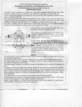
4.1.4 SECONDARY WELDING CONNECTIONS
The secondary output welding terminals, POS (+) and
NEG (-) are located in the lower front panel. Refer to Po-
larity Setup.
4.1.5 WIRE FEED SPEED CONTROL (Figure 8)
The wire feed speed control potentiometer located in the
upper left-hand side, allows wire feed speed adjustments
between 65 and 650 inches per minute (IPM).
4.1.6 VOLTAGE CONTROL (Figure 9)
The arc voltage is controlled with this knob when the Pro-
cess selector switch is in the MIG position. Refer to Weld
Chart and set the recommended setting.
4.1.7 CURRENT CONTROL (Figure 8)
The welding current is controlled with this knob when the
Process selector switch is in the STICK OR TIG position.
Refer to Weld Chart and set the recommended setting.
4.1.8 HOT START (Figure 8)
The Hot Start feature is used to control the amount of
starting current in the Stick welding mode. This helps
ensure positive arc strikes for difficult to start electrodes
and also allows for softer starts on thin material.
SECTION 3 INSTALLATION
4.0 OPERATION
4.1 STANDARD CONTROLS
4.1.1 POWER ON/OFF SWITCH & LAMP
The main power switch is located on the front panel in the
lower right-hand corner. This switch energizes the main
transformer, control circuitry and illuminates the switch
face.
4.1.2 TEMP LAMP (Figure 8)
The TEMP lamp illuminates if an over temperature
condition occurs within the Multimaster 160. This condition
may be caused by excessive duty cycle or over-current
conditions. When an over temperature condition occurs,
the welding output is turned off and the unit must be
allowed to cool. The machine will automatically reset when
the temperature falls to a safe level.
4.1.3 PROCESS SELECTOR SWITCH (Figure 8)
The three position process selector switch is located in
the upper left-hand corner of the control panel. The pro-
cess selector switch provides the visual indication of which
process (STICK, TIG, MIG) has been selected.

17
SECTION 4 OPERATION
Weld Process
Switch
Current Set
Wire Feed
Speed Trim
IPM
Figure 8 - Control Panel
Positive Output
Connection
Negative Output
Connection
Temperature
Lamp
Voltage Set
Main
Power
Switch
Wire Feed Speed
Hot Start
Figure 9 - Front Panel

18
4.2 OPERATING PROCEDURES
Comply with all ventilation, fire and other safety re-
quirements for arc welding as established in the
SAFETY Section at the front of this manual.
4.2.1 MIG WELDING SET-UP
When the PROCESS switch is placed in the MIG position
the Multimaster 160 is set to turn ”ON” when the Mig Gun
trigger is depressed.
Step 1. Choose the weld parameters based of the wire
alloy, diameter, material thickness and shielding
gas from Table 3 - MIG PARAMETERS CHART.
Set the polarity as shown in Filgure 10 for the
process being used.
Step 2. Place the WELD PROCESS (1) switch in the MIG
(FAR RIGHT) position.
Step 3. Turn the Wire Speed Knob (2) to the desired
speed.
Step 4. Turn the VOLTAGE (3) knob to the desired arc
voltage.
Step 5. Pull the gun trigger and start welding. Trim the
wire speed and volts as needed for the desired
arc characteristics.
Figure 10 - MIG Polarity Connection
SECTION 4 OPERATION
Figure 11 - Front Control Panel -
MIG (GMAW) Process Setup
Table 3 - MIG PARAMETERS CHART
Option: If using one, set the shielding gas flow rate to 35
cfh by pulling the gun trigger and turning the ad-
justment knob on the R33-FM 580 Flowmeter.
MIG - DCEP (Electrode Positive)
Work Cable
and Clamp
Polarity
Changeover
Connector
MIG Gun
Connector
1
2
3

19
4.2.2 TIG WELDING SETUP
When the PROCESS switch is placed in the TIG position,
the Multimaster 160 turns “ON” the weld contactor so that
power is immediately available to the output connection. The
Touch TIG starting system is then enabled.
When the WELD PROCESS switch is moved to the TIG
or STICK position, electrode becomes electrically
“HOT”. Do not allow the electrode to contact ground
potential until you are ready to make a weld.
Step 1. Determine the weld parameters based on the metal
thickness in Table 4 or use the ESAB TIG Welding
Handbook for suggested welding parameters.
Figure 12 - TIG Polarity Connection
SECTION 4 OPERATION
Figure 13-Front Control Panel -
TIG (GTAW) Process Setup
Table 4 - TIG PARAMETERS CHART
Step 2. Be sure to set the polarity to DCEN (Electrode
Negative) by placing the Heliarc Torch in the
Negative connection terminal on the front of
the power source as shown in Figure 12.
Step 3. Place the WELD PROCESS (1) switch in the
TIG (center) position.
Step 4. Turn the CURRENT (4) knob to the desired
weld current.
Step 5. Set the shielding gas flow rate to 20 cfh by
opening the manual gas valve on the Heliarc
torch and adjusting the control knob on the R-
33-FM-580 flowmeter.
Step 6. Touch the tungsten electrode to the workpiece
momentarily to establish the welding arc. Trim
the current as desired by turning theCURRENT
(4) knob.
NOTE: The Wirespeed (2) and Volume (3) knobs have no effect in the
TIG mode.
Work Cable
and Clamp
TIG - DCEN (Electrode Negative)
2
1
3
4

20
4.2.3 STICK WELDING SET-UP
When the PROCESS switch is placed in the STICK
position, the Multimaster 160 turns “ON” the weld
contactor so that power is immediately available to the
output connection. This means that the STICK electrode
holder is “HOT”, and an arc will strike when the electrode
comes in contact with the workpiece or any other object
at ground potential.
When the WELD PROCESS switch is moved to the
TIG or STICK position, electrode becomes electrically
“HOT”. Do not allow the electrode to contact ground
potential until you are ready to make a weld.
Step 1. Choose the weld parameters based on the Stick
Electrode and diameter being used from Table 5
- STICK PARAMETERS CHART.
SECTION 4 OPERATION
Figure 15 - Front Control Panel -
STICK (SMAW) Process Setup
Table 5 - STICK PARAMETERS CHART
Step 2. Be sure to set the polarity to DCEP (Electrode
Positive) by placing the Electrode Holder cable in
the Positive connection terminal on the front of
the power source.
In general, choose a polarity based on electrode being
used. Some can be run with straight polarity - electrode
negative. Some can be run with reversed polarity - elec-
trode positive.
Reversed polarity is used when more penetration is re-
quired; typically for thicker material. Straight polarity is used
when you want less penetration; typically for thinner mate-
rial.
Step 3. Place the WELD PROCESS (1) switch in the
STICK (FAR LEFT) position.
Step 4. Adjust the CURRENT (4) knob to the desired weld
current in the top digital display window.
Hot Start gives you a burst of current to ensure easy
arc start. The higher the setting, the bigger the burst.
Step 5. Strike the electrode and start welding. Trim the
welding current as needed for the desired puddle
control.
NOTE: The Wirespeed STICK (2) and Voltage (3) knobs have no
effect in the STICK mode.
STICK - DCEP (Electrode Positive)
Work Cable
and Clamp
2
1
3
4
Figure 14 - STICK Polarity Connection

21
SECTION 5 MAINTENANCE
5.0 MAINTENANCE
5.1 MAINTENANCE AND SERVICE
Be sure that the branch circuit or main disconnect
switch and Multimaster power switch are off or elec-
trical input fuses are removed before attempting any
inspection or work inside the power source. Placing
the power switch on the power source in the off po-
sition does not remove all power from inside the
equipment.
Inspection, troubleshooting and repair of this equip-
ment may ordinarily be undertaken by a competent
individual having at least general experience in the
maintenance and repair of semi-conductor electronic
equipment. Maintenance or repair should not be un-
dertaken by anyone not having such qualifications.
Shut OFF shielding gas supply at source.
5.2 INSPECTION AND SERVICE
Keep equipment in clean and safe operating condition
free of oil, grease, and (in electrical part) liquid and me-
tallic particles which can cause short circuits.
Regularly check cylinder valves, regulators, hoses, and
gas connections for leaks with soap solution or leak test
solution (P/N 998771).
Check for and tighten loose hardware including electrical
connections. Loose power connections overheat during
welding.
Immediately replace all worn or damaged power cables
and connectors. Check for frayed and cracked insulation,
particularly in areas where conductors enter equipment.
The electrode wire and all metal parts in contact with it
are electrically energized while welding. Inspect these
parts periodically for defective insulation and other elec-
trical hazards.
If uninsulated cable and parts are not replaced, an
arc caused by a bare cable or part touching a
grounded surface may damage unprotected eyes or
start a fire. Body contact with a bare cable, connec-
tor, or uncovered conductor can cause a fatal shock.
Keep power cables dry, free of oil and grease, and pro-
tected at all times from damage by hot metal and sparks.
Clean dirt and metal particles from drive roll groove
weekly; replace roll if badly worn.
5.2.1 POWER SOURCE
5.2.1.1 RECTIFIERS AND TRANSISTORS
It is recommended that the internal components be
cleaned occasionally by blowing them out with low pres-
sure compressed air. This cleaning operation is neces-
sary so that maximum cooling will be accomplished by
the air stream. This should be done periodically, depend-
ing upon the location of the unit and the amount of dust
and dirt in the atmosphere.
The hermetically sealed diodes and transistors are spe-
cially designed for welding machine use and will not age
or deteriorate with use. The rectifiers are mounted on heat
sinks. A periodic cleaning of dust and dirt from these is
necessary to insure cooling of the rectifiers. Should any
rectifier need replacement, it can be quickly removed from
the heat sink.
5.2.1.2 FAN MOTOR
All models are equipped with an exhaust fan and rely on
forced draft for adequate cooling for high duty cycles and
overloads.
Do not use filters on this unit as they would restrict
the volume of intake air. Output ratings on this unit
are based on an unobstructed supply of cooling air
drawn over its internal components. Warranty is void
if any type of filtering device is used.
5.2.1.3 TRANSFORMER
Occasional blowing out of the dust and dirt from around
the transformer is recommended. This should be done
periodically depending upon the location of the unit and
the amount of dust and dirt in the atmosphere. The Power
Source case cover should be removed and a clean, dry
low pressure air stream should be used for this cleaning
operation.
5.2.1.4 OVER-TEMPERATURE PROTECTION
The Power Source is protected from high internal tem-
peratures by thermal switches. When the Power Source
is operated under high current applications for long peri-
ods, the thermal switches may reach a high temperature
causing it to de-energize the contactor. These thermal
switches will reset automatically after the heat sink or
transformer windings have cooled to a safe level. While
de-energized, the contactor can not be operated. But, if
the gun trigger is depressed, the unit will still feed wire
and the solenoid will operate.
5.2.2 WIRE FEEDER
As soft wire is fed, the drive rolls may pick up metal from
the wire surface. Accumulation on the rolls may score the
wire with resulting unwanted friction and improper feed-
ing.
Inspect the rolls regularly and clean them with a fine-wire
power brush. Avoid roughening, or removing the hard-
ness of groove surfaces in grooved rolls. Any roughening
may score the wire, just as the accumulation being re-
moved may do.

22
SECTION 5 MAINTENANCE
EMI FILTER (0558002746)
S1 - ROCKER SWITCH 2X16A 250V (0558002747)
RS1 - RECTIFIER 600V 35A (0558002730)
INV8 - INVERTER PCB (0558002716)
CONTFC - CONTROL PCB (0558002717)
BOTTOM PLATE - BOTTOM PLATE 140 160 MET (0558002708)
T1 - TRANSFORMER 230V 17V 15VA (0558002732)
T2 - MAIN TRANSFORMER 10/3 (0558002733)
L1 - COIL 50uH (0558002729)
R201 - R202 - RESISTORS 10R 3W
C201 - C202 - CAPACITORS 4n7 400V
C203 - C204 - CAPACITORS 1000pF 250VAC
D201 - D202 - D203 - D204 - D205 - DIODES 60A 200V
CN1 - CENTRALIZED MIG TORCH CONNECTOR (0558002709)
CN2 - CN3 - CHANGE POLARITY SOCKETS
CN4 - CHANGE POLARITY PLUG
VR1 - FAN 120 X 120 220/230V 50/60Hz (0558002738)
V1 - VARISTOR 275V (0558002731)
SV1 - SOLENOID VALVE 230V (0558002719)
M1 - WIRE MOTOR 17V (0558002710)
/