Cebora 342 TIG Sound DC 2640/T User manual
- Category
- Welding System
- Type
- User manual
This manual is also suitable for

NOTE: The welding machine has also been designed for use
in environments with a pollution rating of 3. (See IEC 664).
1.3 DESCRIPTION OF PROTECTIVE DEVICES
1.3.1 Thermal protection
This device is protected by a thermostat.
When the thermostat is tripped, the machine stops delivering
current but the fan continues to run. The LED AM on the
control panel lights to indicate that the thermostat has been
tripped.
1.3.2 Block protection
This protection is indicated by the LED AN on the control
panel.
2 INSTALLATION
2.1 PLACEMENT
Install the control panel, following the corresponding
instructions.
The welding machine must be placed in a sufficiently
ventilated, non-dusty area, taking care not to obstruct the
air entering or leaving the cooling slots.
WARNING: REDUCED AIR FLOW causes the internal parts
to overheat and may damage them.
• Keep at least 200 mm of free space all around the machine.
• Never connect any filtering device to the air intake passages
of this welding machine.
Use of any type of filtering device shall immediately void the
warranty.
2.2 START-UP
Only skilled personnel should install the machine.
Connections must be carried out according to current
regulations, and in full observance of safety laws (standard
CEI 26-10 - CENELEC HD 427)
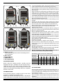
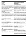
2.3 DESCRIPTION OF THE EQUIPMENT (fig. 1-1a)
A) Negative output terminal (-).
B) Positive output terminal (+).
Note: during the welding, an alternated voltage is
present on the terminals A and B of art. 348.
C) Connector for the TIG torch trigger, foot control or
cooling unit.
The torch pushbutton wires must be connected to pins 1
and 9
INSTRUCTION MANUAL FOR ARC WELDING MACHINES
IMPORTANT!!!
READ THIS MANUAL CAREFULLY BEFORE INSTALLING,
USING OR PERFORMING ANY FORM OF MAINTENANCE
ON THE MACHINE, PAYING SPECIAL ATTENTION TO
THE SAFETY REGULATIONS. CONTACT YOUR
DISTRIBUTOR IF YOU DO NOT FULLY UNDERSTAND
THESE INSTRUCTIONS.
INTRODUCTION
This equipment must be used solely for welding operations.
We urge you to pay especially close attention to the chapter
on safety precautions.
This manual must be carefully stored in a place familiar to
everyone involved with the machine. It must be consulted
whenever doubts arise and accompany the machine
throughout its operative life-span. It shall also serve as a
reference for ordering spare parts.
1 GENERAL DESCRIPTIONS
This welding machine is a constant current power source
built using INVERTER technology, designed to weld covered
electrodes (not including cellulosic) and for TIG procedures,
with scratch start and high frequency. Art. 342 delivers direct
current, while Art. 348 delivers both direct and alternating
current.
In order to be operative, this power source must be
used in combination with one of the control panels
available.
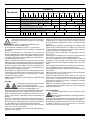
1.2 EXPLANATION OF TECHNICAL SPECIFICATIONS
IEC 974.1 The welding machine is manufactured according
to these international standards EN60974.1.
N°. .......... Serial number. Must be indicated on any type of
............... request
regarding the welding machine.
Three-phase static frequency converter
transformer-rectifier.
Drooping characteristic.
MMA Suitable for welding with covered electrodes.
TIG Suitable for TIG welding.
U0. .......... Secondary open-circuit voltage (peak value).
X............. Duty cycle percentage
The duty cycle expresses the percentage of 10
minutes during which the welding machine may
run at a certain current without overheating.
I2. ........... Welding current
U2. .............. Secondary voltage with current I2
U1. .......... Rated supply voltage
3~ 50/60Hz 50- or 60-Hz three-phase power
supply
I1. ........... Absorbed current at the corresponding current
I2 during welding.
IP23 ........ Protection rating for the housing
Grade 3 as the second digit means that this
equipment is suitable for use outdoors in the rain.
S............ Suitable for use in high-risk environments.
-
A V A V
/ -- -/ -
X
I
2
U
2
%%%%%%
AAAAAA
VVVVVV
AAAAAA
U
0
V
PEAK
U
1
3x400V-50/60Hz
I
1
MMA
MADE
IN ITALY
Nº
X
I
2
U
2
U
0
V
PEAK
U
1
3x400V-50/60Hz
I
1
TIG
S
-
A V A V
/
-- -/ -

fig. 1
fig. 1a
I
V
ADBN NCHGE
F
0
V
I
ADBN NCH G E F
0
D) Fitting (1/4 gas).
This is where the gas hose of the TIG welding torch is
to be connected.
E) Main switch.
F) Power ON lamp.
G) Power cord.
H) Gas supply fitting.
2.4 GENERAL NOTES
Before using this welding machine, carefully read the
standards CEI 26/9 - CENELEC HD 407 and CEI 26.11 -
CENELEC HD 433. Also make sure the insulation of the
cables, electrode clamps, sockets and plugs are intact, and
that the size and length of the welding cables are compatible
with the current used.
2.5 MMA WELDING
• Use electrode clamps in compliance with current safety
regulations, and without protruding screws.
• Make sure that the main switch is set to 0, and that the
power cable plug is not inserted in the power socket. Then
connect the welding cables, observing the polarity required
by the manufacturer of the electrodes you are using.
• The welding circuit must never be deliberately placed in
direct or indirect contact with the safety conductor except on
the workpiece.
• If the workpiece is deliberately grounded by means of the
safety wire, the connection must be as direct as possible,
and made using a wire having a cross-section at least equal
to that of the welding current return wire. It must also be
connected to the workpiece at the same point as the return
wire, using the return wire clamp or a second earth clamp
placed immediately adjacent to it.
• Every precaution must be taken to avoid welding current
leakage.
• Make sure that the supply voltage matches the voltage
indicated on the specifications plate of the welding machine.
• Connect the power cable, making sure that the brown,
black and blue wires correspond to the three phases, and
that the yellow-green wire corresponds to the earth
terminal of the system
• If the machine is used in combination with the cooling unit
Art. 1337 or 1338, it may be powered by means of the socket
E on the cooling unit itself.
• The capacity of the overload cutout switch or fuses
installed in series with the power supply must be equivalent
to the absorbed current I1 of the machine.
• The absorbed current I1 can be determined by reading the
technical specifications indicated on the machine, in regards
to the supply voltage U1 available.
• Any extension cords must be sized appropriately for the
absorbed current I1 .
• Turn the machine on using the main switch E.
• If the machine is powered via the cooling unit, it can be
turned on by means of the switch A located directly on the
cooling unit.
• Do NOT touch the torch or electrode clamp simultaneously
with the mass terminal.
Select MMA on the control panel using the push-button A,
and adjust the current by means of the knob AC.
Always remember to shut off the machine and remove
the electrode from the clamp after welding.
WELDING CABLE CROSS-SECTION in mm
2
CURRENT WELDING MACHINE DISTANCE IN METERS
WELDING IN
AMPERES 15 20 30 40 45 50 60
100 35 35 35 35 50 50 50
150 35 35 50 50 70 70 90
200 35 50 50 70 70 95 100
250 35 50 70 70 95 100 150
2.6 TIG WELDING
• Connect the earth cable connector to the positive pole (+)
of the welding machine, and the clamp to the workpiece as
close as possible to the welding point, making sure there is
good electrical contact.
• The welding circuit must never be placed deliberately in
direct or indirect contact with the safety wire except on the
workpiece.
• If the workpiece is deliberately grounded by means of the

NO
SI
fig.2
safety wire, the connection must be as direct as possible,
and made using a wire having a cross-section at least equal
to that of the welding current return wire. It must also be
connected to the workpiece at the same point as the return
wire, using the return wire clamp or a second earth clamp
placed immediately adjacent to it.
• Every precaution must be taken to avoid welding current
leakage.
• Use a TIG torch appropriate for the welding current, and
connect the power connector to the negative pole (-) of the
welding machine.
• Connect the torch connector to the welding machine
connector C.
• Connect the torch gas hose fitting to the fitting D on the
machine, and the gas hose from the cylinder pressure
regulator to the gas fitting on the rear panel.
• Make sure that the supply voltage matches the voltage
indicated on the specifications plate of the welding machine.
• Connect the power cable, making sure that the brown,
black and blue wires correspond to the three phases, and
that the yellow-green wire corresponds to the earth
terminal of the system
• If the machine is used in combination with the cooling unit
Art. 1337 or 1338, it may be powered by means of the socket
E on the cooling unit itself.
• The capacity of the overload cutout switch or fuses
installed in series with the power supply must be equivalent
to the absorbed current I1 of the machine.
• The absorbed current I1 can be determined by reading the
technical specifications indicated on the machine, in regards
to the supply voltage U1 available.
• Any extension cords must be sized appropriately for the
absorbed current I1 .
• Turn the machine on using the main switch E.
• If the machine is powered via the cooling unit, it can be
turned on by means of the switch A located directly on the
cooling unit.
• Do NOT touch the torch or electrode clamp simultaneously
with the earth clamp.
• Follow the instructions given in the control panel manuals
to adjust the TIG welding parameters.
• Use a 2% thorium tungsten electrode, chosen based on the
table below and prepared as described in paragraph 2.6.1.
electrode diam. direct current
tungsten 2% thorium negative electrode
(red band) (Argon)
0.5mm (0.020") 15A - 40A
1mm (0.040") 25A - 85A
1.6mm (0.060") 70A - 150A
2.4mm (0.095") 150A - 250A
3.2mm (0.130") 200A - 350A
WARNING: ELECTRIC SHOCK CAN BE FATAL!
• Remember to shut off the machine and close the gas
cylinder valve when you have finished welding.
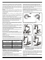
2.6.1 Preparing the electrode
Be especially careful when preparing the electrode tip. Grind
it so that it has vertical grooves as shown in fig.2.
WARNING: LOOSE HOT METAL PARTICLES may injure
personnel, cause fires and damage equipment; TUNGSTEN
CONTAMINATION may lower the quality of the weld.
• Use only a grinder equipped with suitable safety guards to
profile the tungsten electrode, and always wear protective
gear for the face, hands and body.
• To profile the tungsten, use a hard, fine-grained abrasive
grinding wheel used solely for this purpose.
• Grind the end of the tungsten electrode into a tapered
shape, for a length equivalent to approximately 1.5-2 times
the electrode diameter. ( fig. 2)
2.6.2 Recommended welding positions
3 ACCESSORIES
3.1 WIRE FEEDER ASSEMBLY AND CONNECTION
TO THE COOLING UNIT.
This welding machine may be used together with the cooling
unit Art. 1337 or 1338. We recommend that you purchase the
cart Art. 1424, which will allow you to assemble an easily
portable system along with the gas cylinders.
Remove the feet N from both the generator and cooling unit,
and place them on the cart, in the upper and lower sections,
respectively.

Reassemble the feet to fasten the equipment to the cart.
Connect the torch connector or any remote controls to the
socket H of the cooling unit, and the connector I to the socket
C on the generator.
Connect the torch gas fitting to the fitting D on the generator.
Connect the water hoses to the fittings L and L1 of the cooling
unit, making sure the blue hose is connected to the fitting L1
and the red hose to the fitting L.
Connect the power source power cord to the 16-A type
3P+N+T three-phase socket of the cooling unit, then connect
the cooling unit cable to a three-phase power supply.
Always remember that the black, brown and blue wires
correspond to the phases, and the yellow-green wire to
earth.
NOTE: If the cooling unit is shut off, or if the water does not
circulate, a safety device will prevent the welding machine
from operating.
3.2 REMOTE CONTROLS
This equipment may be used with the foot control Art. 193.
If you wish to adjust the current using the pedal and the arc
ignition using the torch, you must use the connection Art.
1180.
This equipment may also be used with the rempte control Art.
187 together with the extension cable Art. 1192.
When the MMA mode is selected, the 10 pole connector of
the extension must be connected to the C connector of the
machine.
When the TIG mode is selected, you must use the connector
Art. 1180.
CAUTION! These steps must be carried out in the sequence
described in order for the machine to recognize the remote
control.
4 MAINTENANCE AND CHECKS
Note: All repair work must be done by qualified personnel.
4.1 GENERAL NOTES
• Do not touch live electrical parts.
• Shut off the welding machine and unplug the power cord
from the socket before all checks and maintenance operations.
MOVING PARTS can cause serious injury.
HOT SURFACES can cause serious burns.
• Let the welding machine cool before performing maintenance.
4.2 REPAIRING THE WELDING MACHINES
Experience has shown that many fatal accidents are caused
by poor repairs. That is why it is just as important to fully
check a repaired welding machine as a new one.
This also protects manufacturers from being held liable for
defects for which others are to blame.
• If the repairs are not performed by the manufacturer,
repaired welding machine in which any components have
been replaced or altered must be marked in such a way as
to identify who carried out the repairs.
5 SAFETY PRECAUTIONS
5.1 ELECTRIC SHOCK
•Disconnect the power cord from the mains
before working on the cables or opening the
machine.
• Never touch live parts
• Never use the machine without the safety guards.
• Insulate yourself from the part to be cut/welded and from
the earth by wearing insulating gloves and clothing.
• Keep all clothing (gloves, shoes, headgear) and your body
dry at all times.
• Do not work in damp or humid environments
• Should you notice even the slightest sensation of electric
shock, stop cutting/welding immediately. Do not use the
equipment again until the problem has been identified and
resolved.
• Include an automatic wall switch of adequate capacity
placed near the equipment, to allow it to be shut off immediately
in case of emergency.
• Inspect the power cord, torch cable, grounding cable and
the torch itself often. Never use the machine if any of these
parts are damaged.
• Make sure the power supply line is fitted with an efficient
grounding socket.
• Plasma cutting equipment requires dangerous voltages to
strike the arc (approximately 250/350 V DC). It is therefore
recommended to take the following precautions during use.
• Never disable the safety devices on the torch and machine.
• If using the system for plasma cutting, always turn off the
machine before replacing the nozzle, isolating diffuser,
electrode or nozzle holder.
• Only screw the nozzle holder onto the head with the
electrode, the isolating diffuser and the nozzle mounted.
If these parts are not present, the machine will not
function properly and operator safety will be endangered.
5.2 RADIATION
• The ultraviolet radiation emitted by the arc may
harm eyes and burn the skin; it is therefore
recommended to wear the appropriate safety
garments and masks.
• Protect anyone around the cutting/welding area. The arc is
hazardous to a distance of up to 15 meters.
• Never look at the arc with your bare eyes!
• Prepare the cutting/welding area to reduce the reflection
and transmission of ultraviolet radiation by painting the walls
and other exposed surfaces black to decrease reflections,
and installing protective screens or curtains to reduce
transmitting ultraviolet rays.
• Do not wear contact lenses! The intense heat issued by the
arc could melt them to the cornea.
The shields and helmet masks provided are in compliance
with the European directive 89/686/CEE and satisfy European
requirements and standards. For your protection, read all of
the enclosed information carefully before using the screens
and masks. This information forms an integral part of directive
89/686/CEE, enclosed in paragraph 1.4.
Make sure that the shield filter strength is appropriate to the
tasks to be carried out. This filter strength is indicated by a
progressive number that must be chosen based on the task
to be carried out.

5.3 FUMES
Cutting and welding produce hazardous fumes and
metal dust that may be hazardous to your health.
Therefore:
• Work only in adequately ventilated areas.
• Keep your head away from fumes.
• Use adequate ventilation systems in closed areas.
• Use approved respirators if the ventilation is not deemed
adequate.
• Clean the material to be cut/welded if any solvents or
halogen degreasers are present that may create toxic gases
during cutting/welding. Some chlorinated solvents may de-
compose in the presence of the radiation emitted by the arc,
and generate phosgene gases.
• Never cut/weld where solvent fumes are present or if the
radiant energy can penetrate atmospheres containing even
the slightest traces of trichloroethylene or perchloroethylene.
• Never cut/weld coated metals or those containing lead,
graphite, cadmium, zinc, chrome, mercury or beryllium if you
are not using an adequate respirator.
• The electric arc generates ozone. Prolonged exposure to
atmospheres containing high concentrations of ozone may
cause headaches, nasal, throat, and eye irritation, serious
congestion and chest pains.
• IMPORTANT: NEVER USE OXYGEN FOR VENTILATION
PURPOSES.
5.4 FIRE
Avoid producing fire due to sparks and hot
scraps or incandescent pieces.
• Make sure that appropriate fire-fighting
devices are available near the cutting/welding area.
• Remove all flammable and combustible materials from the
cutting/welding area and its vicinity (at least 10 meters).
• Do not cut/weld on fuel and lubricate containers, even if
empty. They must be cleaned thoroughly before being cut/
welded.
• Let the cut/welded material cool before touching it or
placing it in contact with combustible or flammable material.
• Do not operate in atmospheres having high concentrations
of combustible fumes or flammable gases and dusts.
• Always check the work area half an hour after cutting to
make sure no fires have started.
• Never keep combustible items such as cigarette lighters or
matches in your pocket.
5.5 BURNS
• Protect your skin against burns from the ultraviolet radiation
emitted by the arc, sparks and scraps of molten metal by
wearing fireproof clothing that covers all exposed body
surfaces.
• Wear protective welder's garments/gloves, headgear and
high-top shoes with reinforced toes. Button your shirt collar
and pocket flaps, and wear trousers without cuffs to prevent
scraps and sparks from falling in them.
• Avoid oily or greasy garments. A single spark could set
them on fire.
• Incandescent metal parts such as pieces of electrode and
the workpiece must always be handled with gloves.
• First aid equipment and a qualified person must be
available for each working shift, unless there are health
facilities nearby for the emergency treatment of eye or skin
burns.
• Use earplugs when working overhead or in a small space.
Use a helmet when others are working above you.
• People getting ready to weld/cut must not use flammable
hair products.
• Wait for the torch to cool, then turn the machine off before
touching the front part of the torch.
• Plasma cutting machines have a pilot arc, thus the arc
strikes as soon as the torch trigger is pressed, even when the
earth cable is disconnected. You must therefore avoid
aiming the jet towards your body or towards the people
present in the cutting area.
• When you are finished cutting, always hang the torch on the
hook provided and turn off the machine to avoid accidentally
striking the plasma arc.
5.6 EXPLOSIONS
• Never cut/weld above or near containers under
pressure.
• Never cut/weld in atmospheres containing explosive
dust, gases or fumes.
• Plasma cutting machines run on compressed air. Take the
appropriate precautions if the air is drawn from cylinders.
Welding/cutting machines use gases such as CO2, ARGON,
or blends of ARGON + CO2 to protect the arc; you must
therefore take the utmost care with:
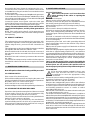
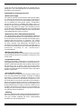
Arc process
Current (A)
0,5 2,5 10 20 40 80 125 175 225 275 350 450
1 5 15 30 60 100 150 200 250 300 400 500
Manual metal arc welding
MIG (heavy metal*)
MIG (light metal)
TIG
MAG
Arc gouging
Plasma cutting
Plasma welding
910 11 12 13 14
10 11 12 13 14 15
456789 10 11 12 13 14 15
10 11 12 13 14
10 11 12 13 14 15
9 1011 1213 14
10 11 12 13 14 15
11 12 13
* The term "heavy metal" covers e.g. stainless steel and copper alloys.

5.6.1 Cylinders
• Large gas leaks may dangerously affect the concentration
of oxygen.
• Never connect the cylinder directly to the machine: use a
pressure regulator.
• The intake pressure must never exceed 6 bar (0.6 MPa) for
plasma cutting machines, and 4 bar (0.4 MPa) for cutting/
welding machines.
• Always observe current regulations when handling or using
cylinders under pressure.
• Never use cylinders that leak or have been physically
damaged.
• Always fasten the cylinders in place.
• Never move cylinders without protecting the valve.
• Use only cylinders whose contents have been clearly
identified.
• Never use oil or grease to lubricate cylinder valves.
• Never place the plasma or welding arc in electrical contact
with the cylinder.
• Never expose the cylinders to excessive heat (greater than
50°C), sparks, molten scraps or flames.
• Never tamper with the cylinder valves.
• Never try to release jammed valves with hammers, wrenches
or other means.
• Never erase or alter the name, number or other markings
on the cylinders. This is both illegal and dangerous.
• Never lift the cylinders off the ground by grasping the valve
or cap, or by using chains, harnesses or magnets.
• Refill the cylinders at authorized centers only.
• The cylinder fittings must never be changed or switched.
5.6.2 Pressure regulators
• Keep pressure regulators in good condition.
• Never use a regulator that leaks or appears physically
damaged.
• Never use oil or grease to lubricate a regulator.
5.6.3 Air/gas hoses
• Replace any hoses that appear damaged.
• Keep hoses stretched taut to avoid creasing.
• Keep any excess hose coiled and away from the work area
to prevent it from being damaged.
5.7 MOVING PARTS
• Moving parts such as the fan may cut fingers and hands
and snag clothing.
• Only qualified personnel may remove guards and coverings
for maintenance, after first disconnecting the power cable.
• Replace all coverings and guards and close the doors when
the task is complete, and before starting the machine.
5.8 NOISE
This machine does not in itself produce noise
above 80 dB. The plasma cutting/welding procedu-
re may produce noise levels above that limit; users
must therefore take all precautions required by law.
5.9 PACEMAKERS
Magnetic fields caused by high currents may affect the
operation of pacemakers. Wearers of any vital electronic
equipment (pacemakers) must consult their physician before
performing arc welding, cutting, deseaming or spot welding.
5.10 ELECTROMAGNETIC COMPATIBILITY
5.10.1General notes
This machine has been built in conformity with the instructions
of harmonized standard EN50199.
In this standard, the limits for electromagnetic emissions are
based on practical experience. However, the machine's
ability to function compatibly with other radio and electronic
systems depends largely on how it is used. The limits set
forth in the above standard may not be adequate to fully
eliminate interference when a receiving apparatus is located
in the immediate vicinity, or is highly sensitive. In these
cases it may be necessary to adopt special measures to
further reduce interference.
This machine must be used solely for professional purposes
in an industrial environment. Keep in mind that it is potentially
difficult to ensure electromagnetic compatibility in non-
industrial environments.
5.10.2Installation and use
The user is responsible for installing and using the cutting/
welding equipment according to the manufacturer's
instructions. If electromagnetic disturbances are detected,
then it shall be the responsibility of the user of the cutting/
welding equipment to resolve the situation with the technical
assistance of the manufacturer. In some cases this remedial
action may be as simple as grounding the cutting/welding
circuit, (see NOTE). In other cases, it could involve constructing
an electromagnetic screen enclosing the cutting/welding
power source and the work complete with associated input
filters. In all cases, electromagnetic disturbances shall be
reduced to the point where they are no longer troublesome.
Note: The cutting/welding circuit may or may not be grounded
for safety reasons. Changing the grounding arrangements
should only be authorized by a person who is competent to
assess whether the changes will increase the risk of injury,
e.g. by allowing parallel cutting/welding current return paths
which may damage the grounding circuits of other equipment.
Further guidance is given in IEC 974-13 "Arc welding
equipment - Installation and use" (under preparation).
6.10.3 Assessing the area
Before installing cutting/welding equipment, the user shall
make an assessment of potential electromagnetic problems
in the surrounding area. The following shall be taken into
account:
a) other supply cables, control cables, signaling and telephone
cables located above, below and adjacent to the cutting/
welding equipment.
b) radio and television transmitters and receivers.
c) computer and other control equipment.
d) safety critical equipment, e.g. guarding of industrial
equipment.
e) the health of the people around, e.g. the use of pacemakers
and hearing aids.
f) equipment used for calibration or measurement.
g) the immunity of other equipment in the environment.
The user shall ensure that other equipment being used in the
environment is compatible. This may require additional
protection measures.
h) the time of day that cutting/welding or other activities are
to be carried out.
The size of the surrounding area to be considered will depend

on the structure of the building and other activities that are
taking place. The surrounding area may extend beyond the
boundaries of the premises.
5.10.4 Methods of reducing emissions
- Mains power supply
The machine must be connected to the mains power supply
according to the manufacturer's instructions. If interference
occurs, it may be necessary to take additional precautions
such as filtering the mains power supply. Consideration
should also be given to shielding the supply cable in a
metallic conduit or equivalent. Shielding should be electrically
continuous throughout its length. The shielding must be
connected to the cutting/welding power source so that good
electrical contact is maintained between the conduit and the
cutting/welding power source enclosure.
- Maintenance of the cutting/welding equipment
The cutting/welding equipment should be routinely maintained
according to the manufacturer's recommendations. All access
and service doors and covers should be closed and properly
fastened while the machine is in operation. The cutting/
welding machine should not be modified in any way, except
for those changes and adjustments described in the
manufacturer's instructions. In particular, the spark gaps of
arc striking and stabilizing devices should be adjusted and
maintained according to the manufacturer's
recommendations.
- Welding and cutting cables
The cutting/welding cables must be kept as short as possible
and should be positioned close together, running at or close
to floor level.
- Equipotential bonding
Bonding of all metallic components in and adjacent to the
cutting/welding installation should be considered. However,
metallic components bonded to the workpiece will increase
the operator's risk of electric shock by touching these
metallic components and the electrode at the same time. The
operator should therefore be insulated from all such bounded
metallic components.
- Grounding the workpiece
If the workpiece is not grounded for electrical safety or due
to its size and position (for example, ship hulls or building
steel-work), a connection bonding the workpiece to earth
may reduce emissions in some but not all instances. Care
should be taken to prevent the grounding of the workpiece
from increasing the risk of injury to users, or damage to other
electrical equipment. Where necessary, the workpiece must
be grounded by means of a direct connection, while in some
countries where direct connections are not permitted, the
bonding may be achieved by suitable capacitance selected
according to national regulations.
- Shielding
Selective shielding of other cables and equipment present in
the surrounding area may alleviate problems of interference.
You may consider shielding the entire cutting/welding
installation for special applications.
-
 1
1
-
 2
2
-
 3
3
-
 4
4
-
 5
5
-
 6
6
-
 7
7


Cebora 342 TIG Sound DC 2640/T User manual
- Category
- Welding System
- Type
- User manual
- This manual is also suitable for
Ask a question and I''ll find the answer in the document
Finding information in a document is now easier with AI
Related papers
-
Cebora 250 Bi Welder1350 User manual
-
-
-
-
-
-
-
-
-
Other documents
-
 ArcOne Inverter Power Sources User manual
-
Snap-On TIG 130i User manual
-
Crossfire DIGITIG 200 Owner's manual
-
EWM inverter TIG 250 DC Operating Instructions Manual
-
 L-TEC PLASMAWELD 202 User manual
-
ESAB 202 AC/DC Inverter Arc Welding Machine User manual
-
-
-
-

