Page is loading ...

HM2617
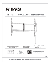
INSTALLATION INSTRUCTION
If you have any questions, please contact us via customerservice@hingear.com
or call us at telephone (626) 645-7128 (USA) Mon - Fri 10am - 6pm (Pacific time).
(B1)
42"~70"
Max:600x400mm/24x16"
Min:200x100mm/8x4"
Für die Installationsanweisungen auf deutsch, Siehe Seite 12~13.
Pour l'instruction en français, veuillez vous reporter à la page 14~15.
Para las instrucciones de la instalación en español, favor vea la página 16~17.
Per le Istruzioni in italiano, vedi pagina 18~19.
TV
1 2
x3
x1

Before getting started, let’s make sure this mount is perfect for you!
1
Is your TV VESA
equal to/greater than
200x100mm/8x4"
and equal to/less than
600x400mm/24x16"?
2
Does your TV
(including accessories)
weigh less than
100 LBS (45.5 KG)?
4
Installation Tools
(Not Included)
Yes --- Perfect!
No --- This mount is NOT compatible.
MAX:600mm/24"
MAX:
400mm/16"
Yes --- Perfect!
No --- This mount is NOT compatible.
Band Tape
2M2M
5
Safety Caution
Please read this instruction carefully before installation.
If you do not understand these instructions or have doubts about the safety of the
installation, assembly or use of this product, contact Customer Service via
[email protected] or call us at telephone (626) 645-7128 (USA) Mon - Fri
10am - 6pm (Pacific time).
● This product is designed for use in wood stud and solid concrete wall.
- DO NOT install into drywall alone.
● The wall must be capable of supporting five times the weight of the TV and mount
combined.
● Do not apply this product to any purpose not indicated by Mounting Dream.
● Incorrect installation may result in product damage or body injury. Mounting Dream shall
bear no responsibility for any damage or injury resulted from incorrect installation,
incorrect assembly or misuse.
Pencil
Screwdriver
Electrodrill
Socket Wrench
1/2"(13mm)
1
3
What is your wall
made of?
Stud Finder Awl
7/32"(5.5mm)
Wood Drill Bit
3/8"(10mm)
Masonry Drill Bit
Hammer
CAUTION:
Drywall with
wood studs?
Solid concrete
wall?

Parts and Hardware
WARNING:
This product contains small items that could be a choking hazard if
swallowed. Before starting assembly, verify all parts are included and undamaged. For parts
shortage or damage, please contact us via customerservice@hingear.com.
NOTE: Not all hardware included will be used.
TV Brackets
x2
M8
M6
M4
1-1 Select TV Screws
TV back
Bracket
Washer
Bracket
Long Screw
Spacer
No, go to PAGE 3 for detailed combination.
Yes, go to PAGE 3 for detailed combination.
TV back
2
1-2 Need Spacer?
Short Screw
Washer
M4x12mm
M6x12mm
M8x25mm
M4x30mm
M6x35mm
M8x45mm
M6x17mm
M8x22mm
M4
M6
10mm
2.5mm
Washers
Spacers
TV Screws
x4 x4
x4 x4
x4 x4
x4
x4
x4
x4
x8
x4

3
Tips: If you need to combine M6(e) or M8(c/f) screw with 2.5mm spacer(j), you have to
remove the inner circle.
1-3 Attach the TV Brackets
Screw and washer
Spacer(s), screw and washer
No!

For wood stud installation, follow STEP 2A
For concrete installation, follow STEP 2B on PAGE 6
<16mm
(5/8")
Max.
16"(406mm)
Min. Wood Stud Size:
nominal 2"(51mm)
actual 1 1/2"(38mm)
Min. Wood Stud Size:
nominal 4"(102mm)
actual 3 1/2"(89mm)
Parts and Hardware
Lag Bolt M8x60mm
M8 Washer
Wood Stud Installation
O
Mounting
Template
x1
x4
4
Centre line
Contact us at telephone (626) 645-7128 (USA)
Mon - Fri 10am - 6pm (Pacific time) or email us by
customerservice@hingear.com to have these
additional pieces shipped directly to you.
Concrete Wall Anchor
4pcs
x4
Wall Plate Unit
x1

16"(406mm)
7/32"
(5.5mm)
2.5"(64mm)
Go to Step 3 on PAGE 7.
5
Centre line
Again, find another wood stud
CAUTION:
To avoid potential personal injury or property damage:
All 4 lag bolts MUST BE firmly tightened to prevent unwanted movement of the wall plate
assembly. Ensure the wall plate assembly is securely fastened to the wall before continuing on to
the next step.
To prevent the TV falling down, the Bolt Head Must Keep UP at this step!!
No!
Bolt Head UP!
Level

Solid Concrete Wall Installation
6
2.5"
(64mm)
3/8"
(10mm)
Concrete Wall
Anchor
DANGER
Min.
8"(203mm)
CAUTION:
To avoid potential personal injury or property damage:
All 4 lag bolts MUST BE firmly tightened to prevent unwanted movement of the wall plate
assembly. Ensure the wall plate assembly is securely fastened to the wall before continuing on to
the next step.
To prevent the TV falling down, the Bolt Head Must Keep UP at this step!!
Level
Bolt Head UP!
No!

7
3-1 Extension Arms Assembly
Allen Key
x1
Parts and Hardware
Extension Arm
x2
Extension Arm
x2
M6x16mm Bolt
x2
M6x12mm Bolt
x4
Supporting Bar
x2
M5x12mm Bolt
x4
x2

8
3-3 Hang and Secure TV to Wall Plate
TV
1 2
100 LBS (45.5 KG)
Before hanging TV, please conduct "wall plate installation integrity test" first.
3-2 Wall Plate Installation Integrity Test

4-1 TV leveling adjustment (±4°):
Loosen 4 leveling bolts on the rear of TV plate by maximum 2
turns, adjust to level, and retighten to secure.
9
4-2 Tilting angle adjustment (+5°/-15°)
:
Pull TV to your desired angle then fasten 2 tilting bolts
with Allen key
Tilting bolts
Tilting bolts
Loosen
Tighten
-15°
+5°

10
Allen key storage: For easy adjustment, you might put the Allen key on
the wall plate as illustration.
/