t Removeallpacking
materials from
insidetheMicrowave
Drawerandtheoven
cavity.DO NOT
REMOVE THE
WAVEGUIDE
COVER,whichis
locatedonthetop
of theMicrowave
Drawerarea.
2 Removethefeature
sticker,ifthereisone.
Checkthedrawerfor
Sealing Surface
Waveguide
Cover
Surface
Microwave
any damage, such as misaligned or bent drawer, damaged drawer
seals and sealing surfaces, broken or loose drawer guides and
dents inside the drawer or on the front side of the drawer. If there
is any damage, do not operate the Microwave Drawer and contact
your dealer or a SHARP AUTHORIZED SERVICER.
_If the information in this manual is not followed
exactly, a fire or electrical shock may result causing property damage,
personal injury or death.
, ALL RANGES CAN TiP
• iNJURY TO PERSONS COULD RESULT
• INSTALL ANTI-TIP BRACKET PACKED
WITH RANGE
• SEE ANTI-TIP BRACKET TEMPLATE
FOR INSTALLATION iNSTRUCTIONS
iNSTALLATiON MANUAL
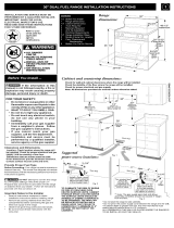
• Before installing the range in an area covered with
linoleum or any other synthetic floor covering, make sure
the floor covering can withstand heat at least 90°F (32.2°C)
above room temperature without shrinking, warping or
discoloring. Do not install the range over carpeting unless
you place an insulating pad or sheet of 1/4-inch (0 64cm) thick
plywood between the range and carpeting.
_ Never leave children alone or unattended in the
area where an range is in use. As children grow, teach them the
proper, safe use of all ranges Never leave the oven door open when
the range is unattended
Stepping, leaning or sitting on the door or drawer
of this range can result in serious injuries and can also cause damage
to the range.
° Do not store items of interest to children in the cabinets
above the range. Children could be seriously burned climbing
on the range to reach items.
* To eliminate the need to reach over the cooktop, cabinet storage
space above the cooktop should be avoided.
. Do not use the oven as a storage space. This creates a
potentially hazardous situation.
. Never use the range for warming or heating the room.
. Do not store or use gasoline or other flammable vapors and
liquids near this or any other range. Explosions or fires could
result.
, Reset all controls to tim "off" position after using a
programmable timing operation.
WHEN USING THE SELF-CLEAN FEATURE:
• Remove broiler pan, food and other utensils before
self-cleaning the oven. Wipe up excess spillage. Follow the
precleaning instructions in the Operation Manual.
To reduce the risk of tipping the range, it must
be secured by properly installed Anti-Tip bracket packed with
the range.
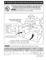
° This range must be electrically grounded in accordance with
local codes, or in their absence, with the National Electrical
Code ANSI/NFPA No. 70--latest edition in United States.
• The installation of ranges designed for manufactured (mobile)
home installation must conform with Manufactured Home
Construction and Safety Standard, title 24CFR, part 3280
[Formerly the Federal Standard for Mobile Home Construction
and Safety, title 24, HUD (part 280)] or when such standard
is not applicable, the Standard for Manufactured Home
Installation 1982 (Manufactured Home Sites, Communities
and Setups), ANSI Z225.1/NFPA 501A- latest edition, or with
local codes in United States.
° Make sure the wall coverings and the cabinets around the range
can withstand the heat generated by the range.
The installer or consumer is responsible for connecting the power
supply cord to the connection block located behind the back panel
access cover.
This range may be connected by means of permanent "hard wiring"
(flexible armored or nonmetallic shielded copper or aluminum cable),
or by means of a power supply cord kit. Only a power supply cord kit
rated at 240 volts or 208 volts and 50 amperes and marked for use
with ranges shall be used. Cord must have either 3 or 4 conductors
to match electric receptacle. The power cord kit is not included so
must be purchase at an appliance store.
For mobile homes, new installations, recreational vehicles or areas
where local codes do not permit grounding through neutral, a 4 con-
ductor power supply cord kit rated at 240 volts or 208 volts minimum,
50 amperes and marked for use with ranges should be used.
Terminals on end of wires must be either closed loop or open-end
spade lugs with upturned ends. Cord must have strain-relief clamp.
The range connection opening should be 1 3/8-inches.